 zishengelectric



news
News Center
Providing high-quality power to the world
Search productSearch post
news
Providing high-quality power to the world
Amorphous transformer cores can reduce no-load losses, but the material name alone does not establish the best transformer for a project. Silicon steel remains a practical option across many designs. When comparing proposals with Zisheng Electric, EPC buyers should evaluate guaranteed performance, actual loading and available equipment configurations before assigning a premium to either core material.
The useful comparison is between complete transformers meeting the same duty. A manufacturer’s percentage improvement for one product family is not a universal saving for every rating, voltage or application.
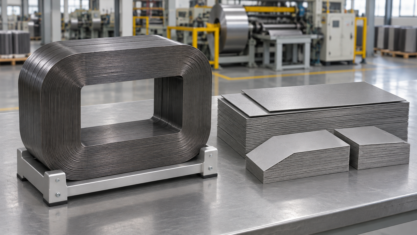
The core carries the alternating magnetic flux that links the windings. Grain-oriented electrical steel is processed to provide favorable magnetic properties along a preferred direction. Amorphous metal has a non-crystalline atomic structure and is formed into very thin ribbon. Material properties and construction influence the energy lost as the magnetic field changes.
Hitachi’s amorphous-transformer information explains the potential to reduce hysteresis and eddy-current losses. Hysteresis loss is associated with repeated magnetic reversal; eddy-current loss arises from currents induced within the conducting core material. These mechanisms help explain lower no-load loss, but the actual guarantee depends on the finished transformer.
This is different from choosing copper or aluminum windings. Core material primarily addresses the magnetic circuit. It does not, by itself, determine winding resistance, cooling performance, external dimensions or the available short-circuit capability.
No-load loss occurs while the transformer is energized at the specified voltage and frequency, even when little useful power is delivered. Load loss changes with current and includes winding and other load-related losses. A lower no-load figure is particularly relevant when a transformer remains energized for many hours at light load.
At higher loading, the load-loss guarantee becomes increasingly important. A simple engineering comparison can approximate the current-dependent loss term with the square of the per-unit load, provided temperature and other assumptions are made consistent. It is an estimate for comparison, not a replacement for detailed thermal or efficiency assessment.
Take a hypothetical pair of equally rated offers. Offer A has 1.0 kW no-load loss and 8.0 kW rated-load loss; Offer B has 0.4 kW and 9.0 kW respectively. At a steady 50% load, the simple totals are 1.0 + 0.5² × 8.0 = 3.0 kW and 0.4 + 0.5² × 9.0 = 2.65 kW. At full load they are 9.0 kW and 9.4 kW. These invented figures illustrate why both guarantees matter; they are not typical material values or Zisheng Electric test results.
| Comparison item | Reason to check it |
|---|---|
| Rating, ratio, frequency and tap basis | Different electrical duties undermine a direct comparison |
| No-load and load-loss guarantees | Both contribute to energy use over the actual duty cycle |
| Temperature and reference conditions | Reported losses must be compared on a consistent basis |
| Cooling, enclosure and installation limits | A lower-loss option must still fit and operate at the site |
| Delivery and supporting evidence | An available, documented design matters more than a material-only claim |
Ask for the daily or seasonal loading profile, including hours energized with little load. An average load percentage can hide peaks because squaring the average is not generally the same as averaging the squared load. Where a lifecycle model is required, the project engineer should use suitable time intervals and the agreed economic assumptions.
A small reduction in losses may have value across many operating hours, but do not invent an electricity tariff, lifetime or discount rate to make one bid appear preferable. Keep the technical comparison separate from the owner’s financial assumptions.
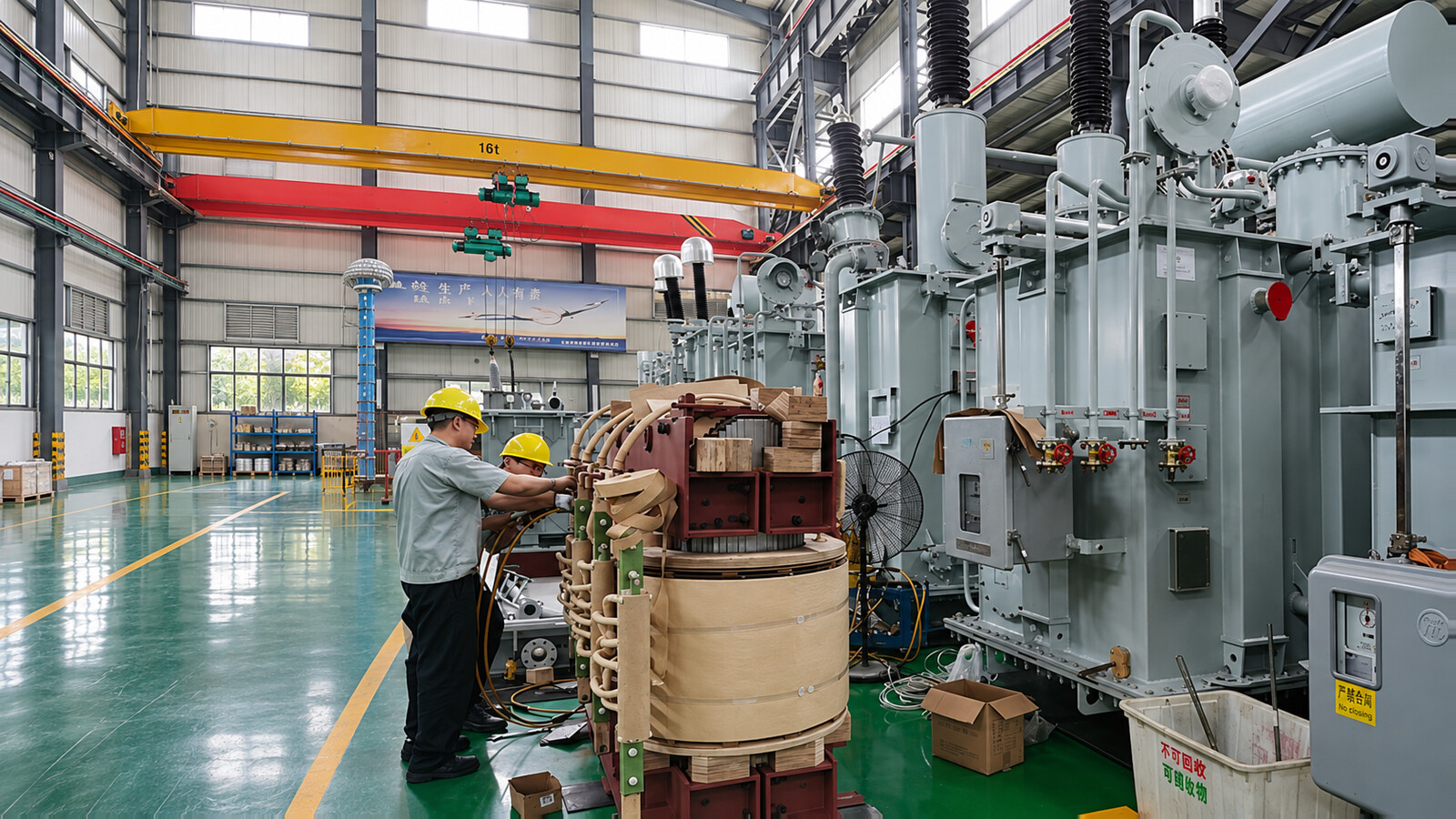
Do not assume an amorphous option is offered at every transmission voltage or power rating. Ask for the manufacturer’s actual design range and relevant evidence. Product-family research or a distribution-transformer brochure does not qualify a different large power transformer automatically.
Conversely, do not dismiss a silicon-steel design simply because another material has lower laboratory core loss. The accepted unit must meet the full specification, including noise, losses, insulation, temperature rise, transport and delivery requirements. Resolve any deviation through the transformer datasheet approval process.
Keep current and loss terminology separate as well: our guide to transformer no-load current explains why a small excitation-current percentage is not a no-load-loss guarantee.
For the 110 kV–115 kV power transformer range, discuss the stated silicon-steel design and required loss guarantees with Zisheng Electric. If an alternative core material is desired, request written confirmation of availability rather than assuming it from this comparison. Supply the operating profile and site constraints so the offer can be assessed as a complete solution.
Reference: Hitachi Industrial Equipment Systems’ amorphous-core explanation. Its product-specific savings are not transferred to other manufacturers or ratings.
After years of working on-site with EPC projects, I have realized one critical truth: although transformers seem to be standard electrical equipment, every actual project requires customized support. Tiny differences in design parameters, dimensio...
View details
Plan substation time synchronization acceptance with clock-source records, endpoint checks, event-time comparisons, loss-of-sync behavior and controlled EPC handover evidence.
View details
Why Tropical-Ready Design Determines Project Reliability A transformer failure in a Vietnamese coastal industrial park or a Thai solar farm is never just a component issue. Production halts. Revenue slides. The unplanned maintenance costs no proje...
View details
Learn practical transformer maintenance experience to extend service life. Cover oil‑immersed & dry‑type transformer inspection, DGA oil testing, temperature control, overload management, environment‑adapted checklists for Middle East & Africa pro...
View details