 zishengelectric






Project Partners
Phone/WhatsApp: 8619131285373
Email: info@zishengtransformer.com
Factory Headquarters: No. 118, Jingyi Street, Economic Development Zone.
Search productSearch post
Project Partners
Phone/WhatsApp: 8619131285373
Email: info@zishengtransformer.com
Factory Headquarters: No. 118, Jingyi Street, Economic Development Zone.
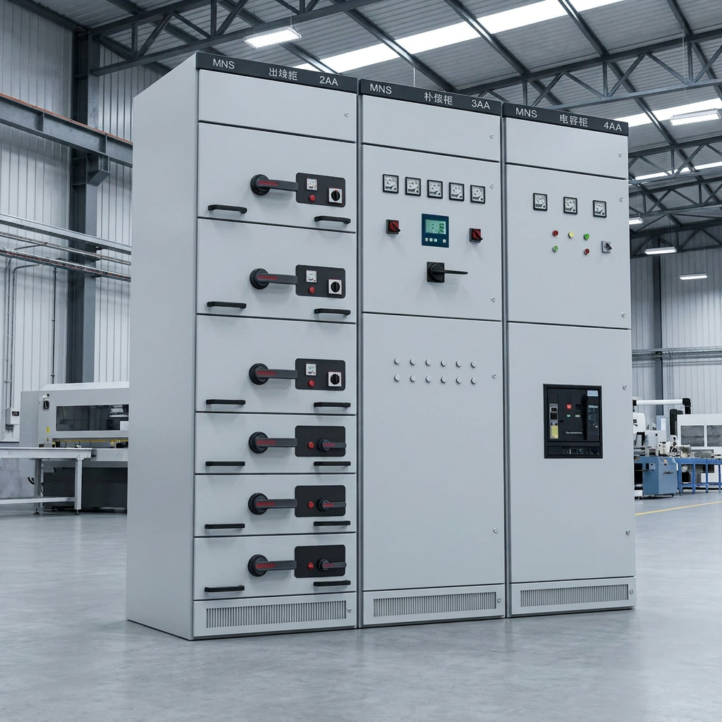
Custom 380V 660V Low-Voltage Switchgear is a modular low-voltage power distribution and control system designed for AC power distribution, motor control, power conversion and electrical equipment protection.
The switchgear is available for 380V and 660V low-voltage systems and can be customized according to project requirements, including rated current, busbar configuration, feeder arrangement, protection devices, enclosure protection, internal separation and control functions.
The MNS-type configuration is particularly suitable for applications requiring flexible feeder combinations, compact installation and convenient maintenance. Typical systems use modular compartments and withdrawable or fixed functional units. Similar 380/660V MNS systems commonly support 50/60Hz operation and high-current busbar configurations.
The equipment can be engineered according to IEC 61439-1 and IEC 61439-2, with other standards available according to the destination market and project specification. IEC 61439-1 defines general construction, service-condition, technical and verification requirements, while IEC 61439-2 provides specific requirements for power switchgear and controlgear assemblies.
The switchgear can be configured according to the project's electrical design, including:
The modular internal structure allows different functional units to be combined according to project requirements.
Typical options include:
Depending on the configuration, the main busbar and vertical busbar can be engineered for high-current applications.
Typical MNS systems available in the market cover busbar ratings from hundreds of amperes to several thousand amperes, with some configurations reaching 6300A or higher.
The enclosure and internal separation can be customized to improve:
Internal separation can be designed according to the required Form 2, Form 3 or Form 4 configuration.
Withdrawable units allow maintenance personnel to isolate and remove individual functional units without shutting down the entire switchboard, where the system configuration permits.
This is particularly useful for:
| Item | Specification |
|---|---|
| Product Type | Low-Voltage Switchgear |
| Rated Voltage | 380V / 660V AC |
| Rated Insulation Voltage | Up to 1000V, depending on design |
| Frequency | 50Hz / 60Hz |
| Phase | 3 Phase |
| System | 3P3W / 3P4W / 3P5W |
| Rated Current | Customized |
| Main Busbar Current | Customized, typically up to several thousand amperes |
| Vertical Busbar | Customized |
| Short-Time Withstand Current | Customized according to project requirements |
| Peak Withstand Current | Customized |
| Protection Degree | IP30 / IP40 / IP42 / IP54, optional |
| Internal Separation | Form 2 / Form 3 / Form 4 |
| Installation | Indoor / Outdoor |
| Structure | Fixed / Withdrawable |
| Cooling | Natural Ventilation / Forced Cooling if required |
| Incoming | ACB / MCCB / Switch Disconnector |
| Outgoing | MCCB / MCB / Fuse / Motor Feeder |
| Control | Manual / Automatic / PLC |
| Metering | Ammeter / Voltmeter / Power Meter / Multifunction Meter |
| Protection | Overcurrent / Short Circuit / Earth Fault / Other |
| Enclosure Material | Painted Steel |
| Busbar Material | Copper / Aluminum |
| Main Standard | IEC 61439-1 / IEC 61439-2 |
| Customization | Available |
Note: Final ratings should not be selected only from the nominal 380V/660V system voltage. The required rated current, short-circuit withstand capability, temperature-rise performance, IP rating and internal separation need to be verified for the complete assembly according to the applicable IEC 61439 requirements.
The incoming section can be equipped with:
The busbar system distributes electrical power between incoming and outgoing circuits.
Available options include:
Busbar sizing is determined according to rated current, short-circuit withstand requirements, temperature rise, installation conditions and project specifications.
Outgoing circuits can be customized for:
A modular low-voltage switchgear solution designed for power distribution and motor control.
Typical characteristics include:
Suitable for applications where simple structure and economical installation are preferred.
Suitable for critical industrial applications where maintenance flexibility and operational continuity are important.
Designed for centralized control and protection of motors.
Typical applications include:
| Configuration | Available Options |
|---|---|
| Rated Voltage | 380V / 400V / 415V / 440V / 480V / 525V / 660V |
| Frequency | 50Hz / 60Hz |
| Rated Current | Project-specific |
| Main Breaker | ACB / MCCB |
| Feeder Breaker | MCCB / MCB / Fuse |
| Structure | Fixed / Withdrawable |
| Busbar | Copper / Aluminum |
| Neutral | 3P3W / 3P4W / 3P5W |
| IP Rating | IP30–IP54 |
| Internal Separation | Form 2 / Form 3 / Form 4 |
| Metering | Standard / Multifunction |
| Protection | Standard / Advanced |
| Control | Manual / Automatic / PLC |
| Communication | RS485 / Modbus / Other |
| Enclosure | Indoor / Outdoor |
| Cable Entry | Top / Bottom |
| Color | Customized |
| Installation | Floor-mounted |
| Special Environment | Dust / Humidity / High Temperature / Corrosive Environment |
Depending on the project, the switchgear can integrate:
For smart power distribution projects, communication interfaces can also be integrated for connection with PLC, SCADA, BMS or energy management systems.
The 380V/660V low-voltage switchgear can be used in a wide range of power distribution and industrial applications.
Each customized switchgear assembly should be manufactured according to the approved technical drawings and project specifications.
The typical production process includes:
Technical Specification Review
→ Electrical Design
→ Layout & SLD Confirmation
→ Component Selection
→ Enclosure Fabrication
→ Busbar Processing
→ Electrical Assembly
→ Wiring & Inspection
→ Routine Verification
→ Final Inspection
→ Packing & Shipment
For IEC 61439 assemblies, verification covers relevant construction and performance characteristics, while routine verification is carried out on each completed assembly.
Typical factory inspection and testing can include:
Where applicable, verification is carried out according to the relevant requirements of IEC 61439-1 / IEC 61439-2.
The switchgear can be engineered for different operating environments.
Typical considerations include:
For harsh environments, additional protection such as higher IP rating, improved surface treatment, special ventilation or anti-corrosion measures can be specified.
Project-Specific Design
Designed around your actual SLD, load list and installation requirements.
Flexible Configuration
Incoming, outgoing, motor control and auxiliary circuits can be arranged according to the project.
International Standards
Designed according to applicable IEC 61439 requirements for low-voltage assemblies.
Factory Direct Supply
Engineering, manufacturing, testing and export packing can be handled by one manufacturer.
Suitable for EPC Projects
Technical drawings, component lists, wiring diagrams, inspection documents and other project documentation can be provided according to contract requirements.
For overseas EPC projects, the following documents can be supplied according to project requirements:
For an accurate quotation, customers are recommended to provide:
For customized switchgear, an SLD and load list are especially useful because they allow the manufacturer to determine feeder arrangement, breaker ratings, busbar capacity and cabinet configuration rather than quoting from voltage alone. IEC itself provides guidance on specifying assembly characteristics and application requirements
The Custom 380V 660V Low-Voltage Switchgear can be configured according to the electrical system, load requirements, installation environment, and project specifications. The following parameters are typical reference values; final ratings are confirmed during engineering design.
| Item | Technical Specification |
|---|---|
| Product Type | Low-Voltage Switchgear / Distribution Switchboard |
| Model | MNS / Customized |
| Rated Voltage | 380V / 400V / 415V / 440V / 480V / 660V AC |
| Rated Insulation Voltage | Up to 1000V AC |
| Rated Frequency | 50Hz / 60Hz |
| System Configuration | 3P3W / 3P4W / 3P5W |
| Rated Current | Customized according to load requirements |
| Main Busbar Current | Up to 6300A, customized |
| Vertical Busbar Current | Customized according to feeder configuration |
| Rated Short-Time Withstand Current | Customized according to system short-circuit level |
| Peak Withstand Current | Customized according to project requirements |
| Short-Circuit Protection | ACB / MCCB / MCB / Fuse |
| Incoming Feeder | ACB / MCCB / Switch Disconnector |
| Outgoing Feeders | MCCB / MCB / Fuse / Motor Feeder |
| Structure | Fixed / Withdrawable |
| Functional Units | Fixed / Plug-in / Withdrawable Drawer |
| Internal Separation | Form 2 / Form 3 / Form 4 |
| Enclosure Protection | IP30 / IP40 / IP42 / IP54, optional |
| Enclosure Material | Cold-Rolled Steel / Galvanized Steel |
| Busbar Material | Copper / Aluminum |
| Main Busbar | Horizontal Copper/Aluminum Busbar |
| Distribution Busbar | Vertical Busbar, customized |
| Neutral Busbar | N Busbar, optional |
| Earth Busbar | PE / PEN Busbar |
| Cable Entry | Top / Bottom |
| Installation | Indoor / Outdoor |
| Cooling Method | Natural Ventilation / Forced Ventilation, optional |
| Metering | Ammeter / Voltmeter / Multifunction Power Meter |
| Protection Functions | Overload / Short Circuit / Earth Fault / Overvoltage / Undervoltage |
| Motor Control | DOL / Star-Delta / Soft Starter / VFD, optional |
| Power Factor Compensation | Capacitor Bank, optional |
| ATS Function | Optional |
| Surge Protection | SPD, optional |
| Communication | RS485 / Modbus RTU / Other protocols, optional |
| Control System | Manual / Automatic / PLC Control |
| Monitoring | Local / Remote Monitoring, optional |
| Operating Environment | Customized according to project conditions |
| Ambient Temperature | Typically -5°C to +40°C, subject to design requirements |
| Installation Altitude | Standard configuration subject to applicable requirements; high-altitude customization available |
| Relative Humidity | Suitable for normal industrial environments; customized for high-humidity applications |
| Corrosion Protection | Standard / Enhanced coating system, optional |
| Color | RAL color or customized |
| Applicable Standard | IEC 61439-1 / IEC 61439-2 |
| Testing | Routine Verification and Functional Testing |
| Customization | Electrical configuration, dimensions, components and protection functions can be customized |
Incoming Section
Busbar Section
Outgoing Section
For a typical 380V/660V industrial power distribution system, the switchgear can be configured as:
Incoming ACB → Main Busbar → Bus Coupler → Outgoing MCCB/MCB Feeders → Motors / Transformers / Production Equipment
The final rated current, short-circuit withstand level, busbar size, breaker specifications and cabinet dimensions should be determined from the Single Line Diagram (SLD), load list and project short-circuit calculation, rather than from the 380V/660V system voltage alone. IEC 61439-1/-2 specifies the relevant requirements and verification framework for low-voltage assemblies.
The 380V/660V Low-Voltage Switchgear can be customized according to the project's electrical design, load requirements, installation environment, and local standards.
| Customization Item | Available Options |
|---|---|
| Rated Voltage | 380V / 400V / 415V / 440V / 480V / 660V |
| Frequency | 50Hz / 60Hz |
| Rated Current | Customized according to load requirements |
| Main Busbar | Copper / Aluminum |
| Busbar Capacity | Customized according to rated current |
| Incoming Breaker | ACB / MCCB / Switch Disconnector |
| Outgoing Breakers | MCCB / MCB / Fuse |
| Cabinet Structure | Fixed / Withdrawable |
| Drawer Type | Fixed / Plug-in / Withdrawable |
| Internal Separation | Form 2 / Form 3 / Form 4 |
| Protection Rating | IP30 / IP40 / IP42 / IP54 |
| Cable Entry | Top Entry / Bottom Entry |
| Installation | Indoor / Outdoor |
| Cabinet Dimensions | Customized according to equipment and site conditions |
| Cabinet Layout | Single Cabinet / Multiple Cabinets / Custom Arrangement |
| Incoming Quantity | Single / Dual / Multiple Incoming |
| Bus Coupler | Manual / Automatic |
| Outgoing Feeder Quantity | Customized according to SLD |
| Motor Control | DOL / Star-Delta / Soft Starter / VFD |
| Power Factor Compensation | Capacitor Bank / Automatic Compensation |
| Metering | Ammeter / Voltmeter / Multifunction Power Meter |
| Protection Functions | Overload / Short Circuit / Earth Fault / Overvoltage / Undervoltage |
| Surge Protection | SPD, Optional |
| ATS | Automatic Transfer Switch, Optional |
| Control System | Manual / Automatic / PLC |
| Communication | RS485 / Modbus RTU / Other Protocols |
| Remote Monitoring | Optional |
| Neutral System | 3P3W / 3P4W / 3P5W |
| Earthing System | TN-S / TN-C / TN-C-S / TT, according to project |
| Enclosure Material | Painted Steel / Galvanized Steel |
| Surface Treatment | Standard / Anti-Corrosion Coating |
| Color | RAL Color / Customer Specified |
| Operating Environment | Standard / High Humidity / Dusty / Corrosive Environment |
| Altitude | Standard / High-Altitude Customized |
| Cooling | Natural Ventilation / Forced Ventilation |
| Special Requirements | Seismic / High Temperature / Corrosion Protection / Other |
The switchgear can be designed around the customer's Single Line Diagram (SLD) and load list. The manufacturer can customize the number and arrangement of incoming feeders, bus couplers, outgoing feeders, motor control units, metering sections, and auxiliary circuits.
Depending on the project budget and technical specification, the switchgear can accommodate internationally recognized or locally approved components, such as:
Component brands and models can be specified by the customer or selected by the manufacturer according to the project requirements.
For EPC and overseas projects, the switchgear can be customized based on:
Recommended information for customization:
Rated Voltage + Rated Current + Frequency + Short-Circuit Level + SLD + Feeder List + IP Rating + Internal Separation + Installation Environment + Applicable Standard.
The Custom 380V 660V Low-Voltage Switchgear is professionally packed according to the cabinet dimensions, weight, transportation method, destination, and project requirements. The packing process is designed to protect the switchgear, electrical components, painted surfaces, and internal connections during long-distance international transportation.
Before packing, each switchgear assembly is inspected to confirm:
The packing list and shipping documents are checked against the final approved configuration before shipment.
Sensitive components are protected before the cabinet is sealed.
Typical protection measures include:
For withdrawable switchgear, drawer units and removable components can be secured separately to prevent movement during transportation.
For overseas sea transportation, additional moisture protection can be provided.
Typical measures include:
This is particularly important for shipments exposed to high humidity, long transit times, or tropical climates.
The standard export packing can include:
Electrical Switchgear → Protective Film → Moisture Protection → Shock-Absorbing Material → Export Wooden Case / Wooden Frame → External Marking
Heavy switchgear cabinets are reinforced to reduce the risk of movement, impact, or deformation during loading and unloading.
For international shipments, suitable export-grade wooden packaging can be used according to the transportation requirements.
The wooden case can provide protection against:
Wooden packaging for international shipments can be prepared in accordance with applicable phytosanitary requirements, including ISPM 15 where required by the destination country.
Depending on cabinet dimensions and shipment quantity, the switchgear can be arranged for:
The loading arrangement is planned according to cabinet dimensions and weight to maximize container utilization while maintaining safe handling.
Heavy cabinets are positioned and secured appropriately to minimize movement during transportation.
We can support different international transportation methods:
Sea Freight
Suitable for large EPC projects and multiple switchgear cabinets.
Air Freight
Available for urgent shipments or small quantities.
Truck Transportation
Suitable for inland transportation from the factory to the port or designated project location.
Multimodal Transportation
Sea + truck or other combinations can be arranged according to the destination and project requirements.
Depending on the contract and destination country, shipping documentation can include:
For EPC projects, the packing method can be customized according to:
Cabinets can also be marked with cabinet number, project number, lifting position, installation position, weight, dimensions, and handling instructions to facilitate identification and installation at the project site.
Before shipment, the customer can receive relevant shipping information such as:
For EPC projects, switchgear can be packed and labeled according to the approved cabinet layout and project installation sequence, helping the site team identify and install each cabinet more efficiently.
The Custom 380V 660V Low-Voltage Switchgear undergoes comprehensive inspection and testing before delivery to verify electrical performance, mechanical operation, wiring accuracy, and overall assembly quality. Testing is carried out according to the approved technical specifications, drawings, and applicable IEC 61439 requirements.
The complete switchgear assembly is inspected for:
The actual assembly is checked against the approved General Arrangement Drawing, Single Line Diagram, and wiring diagrams.
Mechanical components are checked to ensure reliable operation.
Testing may include:
Withdrawable units are checked for correct operating positions, including service, test, and isolated positions where applicable.
All internal electrical connections are checked before energization.
Inspection includes:
Terminal numbers and cable identification are verified against the approved wiring diagrams.
The protective earthing circuit is inspected to confirm continuity between exposed conductive parts and the protective earth system.
The test helps verify that the cabinet structure, doors, panels, and other relevant conductive components are properly connected to the protective circuit.
Insulation resistance is tested between relevant electrical circuits and between live conductors and earth.
The test helps identify:
The test voltage and acceptance criteria are selected according to the applicable product standard and project requirements.
A dielectric withstand test can be performed to verify the insulation capability of the completed assembly.
The test helps confirm that the switchgear can withstand the specified power-frequency test voltage without:
The test parameters are determined according to the applicable IEC requirements and rated insulation characteristics.
Control and protection functions are tested according to the approved electrical design.
Typical checks include:
Protection devices are checked to ensure correct configuration and operation.
Depending on the project, testing may cover:
Protection settings are verified against the approved protection coordination requirements.
Where multifunction meters or monitoring systems are installed, the manufacturer can verify:
The main and distribution busbars are checked for:
Special attention is given to bolted connections and busbar joints.
For low-voltage assemblies covered by IEC 61439, routine verification is performed on each completed assembly to confirm that the manufactured switchgear complies with the specified design and construction requirements.
Typical verification areas include:
After testing, relevant test records can be provided according to the project requirements, including:
For EPC projects, test documentation can be prepared according to the customer's ITP, inspection requirements, approved drawings, and project specifications.
Incoming Component Inspection
↓
Assembly Inspection
↓
Mechanical Operation Test
↓
Wiring & Connection Inspection
↓
Protective Circuit Test
↓
Insulation Resistance Test
↓
Dielectric Withstand Test
↓
Functional & Protection Test
↓
Final Inspection
↓
Test Report & Release for Shipment
Note: Routine tests are performed on the completed assembly. Design verification and project-specific performance verification are handled according to the applicable IEC 61439-1 / IEC 61439-2 requirements and the agreed technical specification.
Each Custom 380V 660V Low-Voltage Switchgear is subjected to routine testing before shipment to verify that the completed assembly has been correctly manufactured, wired, assembled, and tested according to the approved technical documents and applicable IEC 61439-1 / IEC 61439-2 requirements.
The finished switchgear is inspected against the approved drawings and technical specifications.
The inspection includes:
All mechanically operated components are checked for smooth and reliable operation.
Testing includes:
For withdrawable switchgear, the operating positions are checked according to the specified configuration.
The protective circuit is checked to ensure reliable electrical continuity between exposed conductive parts and the protective earth system.
The inspection covers:
This test helps ensure proper grounding continuity and operator safety.
All internal wiring and electrical connections are checked against the approved electrical drawings.
Inspection includes:
Wire numbers, terminal numbers and cable identification are also checked.
Insulation resistance is tested between relevant live conductors and between live circuits and earth.
The test is intended to identify potential:
The test voltage and acceptance criteria are selected according to the applicable standard and project requirements.
A power-frequency withstand test is performed where required to verify the dielectric strength of the completed assembly.
The test checks the insulation system for abnormal:
The test voltage and duration are determined according to the applicable IEC requirements and the rated insulation characteristics of the switchgear.
Relevant electrical clearances and creepage distances are inspected to ensure that the completed assembly complies with the required insulation coordination.
Inspection areas include:
The installed components are checked against the approved Bill of Materials and technical specification.
Typical items include:
The following information is verified where applicable:
The complete control system is tested to verify correct operation.
Typical tests include:
Installed measuring and indication devices are checked for correct wiring and operation.
Depending on configuration:
Communication interfaces such as RS485/Modbus can also be checked when included in the project specification.
Protection devices are inspected and, where required, functionally tested according to the approved protection settings.
Possible functions include:
Protection settings are checked against the approved coordination study or customer requirements.
The busbar system is inspected for:
The actual busbar configuration is checked against the approved drawings.
The manufacturer verifies that all required identification marks are correctly installed.
This may include:
A final inspection is performed before the switchgear is released for packing.
The manufacturer checks:
A Routine Test Report can be provided for each completed switchgear assembly.
Typical records include:
Visual Inspection
↓
Mechanical Operation Test
↓
Protective Circuit Continuity Test
↓
Wiring & Connection Verification
↓
Insulation Resistance Test
↓
Dielectric Withstand Test
↓
Functional & Protection Test
↓
Metering & Communication Test
↓
Final Inspection
↓
Routine Test Report
For EPC projects, the routine testing procedure can be aligned with the approved Inspection & Test Plan (ITP), customer specifications, approved drawings and IEC 61439 requirements. This provides traceable quality records before the switchgear is packed and shipped.
The Custom 380V 660V Low-Voltage Switchgear is designed for low-voltage power distribution, electrical protection, motor control, and energy management. With flexible configurations and customized electrical components, it can be adapted to different industrial, commercial, infrastructure, and energy projects.
Low-voltage switchgear is used as the main power distribution equipment in manufacturing facilities.
Typical applications include:
The switchgear can integrate multiple outgoing feeders to distribute power to different production areas.
Mining operations often require high-capacity and reliable power distribution equipment.
Applications include:
Customized protection and motor-control sections can be configured according to the mining electrical system.
The switchgear can be used for low-voltage power distribution in oil and gas facilities, subject to the applicable area classification and project requirements.
Typical loads include:
For demanding environments, enclosure protection, corrosion resistance, and component selection can be customized.
Low-voltage switchgear is widely applicable to water treatment and wastewater facilities.
It can supply and control:
Motor control feeders can be configured with contactors, soft starters, or variable-frequency drives.
The switchgear can be used for low-voltage power distribution within solar power facilities.
Typical applications include:
The configuration can be customized according to inverter capacity, feeder quantity, system voltage, and project protection requirements.
For BESS projects, low-voltage switchgear can be integrated into the auxiliary and AC distribution system.
Applications include:
Protection and monitoring functions can be customized according to the BESS design.
The switchgear can be used for low-voltage distribution in:
Typical functions include generator auxiliary power, plant distribution, motor control, and emergency power distribution.
The switchgear provides centralized low-voltage power distribution for large commercial facilities.
Typical applications include:
It can distribute power to lighting, HVAC, elevators, pumps, fire systems, and other building services.
For data centers, low-voltage switchgear can be configured for reliable distribution of critical and auxiliary loads.
Applications include:
Dual incoming supplies, bus couplers, automatic transfer functions, monitoring, and other redundancy features can be incorporated when required by the project.
The switchgear is suitable for various infrastructure facilities, including:
The equipment can be customized for different load types, environmental conditions, and power distribution requirements.
Heavy industrial facilities often require high-current distribution and motor control.
Typical loads include:
High-current busbars and withdrawable functional units can be selected for applications requiring flexible maintenance and operation.
The switchgear can serve as part of an integrated low-voltage distribution system for:
It can integrate power monitoring, automatic transfer, protection, and communication functions according to the system architecture.
| Industry | Typical Application |
|---|---|
| Manufacturing | Factory Power Distribution |
| Mining | Motor & Equipment Distribution |
| Oil & Gas | LV Power Distribution |
| Water Treatment | Pump & Motor Control |
| Solar PV | AC Distribution |
| BESS | Auxiliary Power Distribution |
| Power Generation | Plant Auxiliary Power |
| Data Centers | Critical & Auxiliary Loads |
| Commercial Buildings | Building Power Distribution |
| Infrastructure | Utility & Facility Distribution |
| Cement Plants | Heavy Motor Loads |
| Renewable Energy | Microgrid & Energy Distribution |
Utility / Transformer / Generator
↓
380V / 660V Main Incoming Switchgear
↓
Main Busbar
↓
Bus Coupler / Distribution Section
↓
MCCB / MCB / Motor Feeders
↓
Motors / Pumps / HVAC / Production Equipment / Auxiliary Loads
The exact configuration is customized according to the project's Single Line Diagram (SLD), load list, short-circuit level, voltage system, protection requirements, installation environment, and applicable standards.
380V/660V low-voltage switchgear is a complete electrical assembly used for power distribution, circuit protection, monitoring, and control in low-voltage AC systems. It can integrate circuit breakers, busbars, meters, protection devices, control components, and communication modules into one cabinet system.
The main difference is the system rated voltage and the corresponding insulation, clearance, protection, and component requirements. The switchgear can be engineered for 380V, 660V, or other low-voltage systems according to the project electrical design.
Yes. The switchgear can be customized according to the customer's:
The switchgear can be designed and manufactured according to applicable IEC 61439-1 and IEC 61439-2 requirements. Other standards or customer-specific specifications can be considered according to the project and destination market.
Yes. MNS-type modular low-voltage switchgear can be supplied in fixed or withdrawable configurations. The internal arrangement can be customized according to the SLD and feeder requirements.
Both options are available.
Fixed type is suitable for simpler and more economical installations.
Withdrawable type is suitable for applications requiring convenient maintenance, feeder isolation, and flexible operation.
Typical options include:
Higher protection levels can be considered for dusty, humid, or demanding installation environments, subject to the required thermal and ventilation design.
Yes. The assembly can be configured with different internal separation arrangements, such as:
The appropriate configuration depends on safety requirements, maintenance practices, and project specifications.
Depending on the application, the switchgear can accommodate:
Breaker ratings and breaking capacities are selected according to the actual system requirements.
Yes. Component brands can be specified according to the customer's technical requirements and project budget.
The switchgear can be configured with suitable:
Yes. The switchgear can incorporate motor control feeders for pumps, fans, compressors, conveyors, production machinery, and other industrial motors.
Motor control options may include:
Yes. An ATS (Automatic Transfer Switch) or automatic bus transfer system can be integrated when required.
This can be used for systems with:
Yes. Communication and monitoring functions can be integrated according to the project requirements.
Common options include:
Yes, but outdoor applications require appropriate enclosure, weather protection, ventilation, corrosion protection, and environmental design.
The required IP rating and construction should be confirmed according to the actual site conditions.
Yes. The design can be adapted for demanding environments by considering:
The actual environmental conditions should be provided during the quotation stage.
Yes. Cabinet width, depth, height, compartment arrangement, cable entry, and overall lineup configuration can be customized according to the electrical components and installation space.
For EPC projects, cabinet dimensions can be developed according to the approved General Arrangement (GA) drawing.
Yes. The main and distribution busbars can generally be configured using copper or aluminum, depending on electrical requirements, current rating, temperature-rise requirements, and project specifications.
For an accurate quotation, customers should provide:
Providing the SLD and load list allows the manufacturer to prepare a more accurate technical and commercial proposal.
Routine testing can include:
A Routine Test Report can be supplied according to the project requirements.
Yes. Factory Acceptance Testing (FAT) can be arranged according to the approved ITP, technical specification, drawings, and customer inspection requirements.
Customers or third-party inspectors can participate in the inspection when required by the contract.
The switchgear is protected against impact, dust, moisture, and movement during transportation. Depending on the shipping method, packaging can include:
Container loading can also be arranged according to cabinet dimensions and project requirements.
Yes. Depending on the project, documentation can include:
Yes. The switchgear can be customized for industrial plants, mining, renewable energy, infrastructure, data centers, water treatment, manufacturing, commercial buildings, and other EPC projects.
Technical drawings, component selection, testing, documentation, export packing, and delivery can be coordinated according to the project schedule.
The delivery time depends on the cabinet quantity, electrical configuration, component brands, customization level, testing requirements, and project documentation.
A confirmed delivery schedule can be provided after the technical specification and configuration are finalized.
Yes. Customer-provided SLD, GA drawings, wiring diagrams, technical specifications, and component lists can be reviewed by the engineering team.
The manufacturer can then prepare the switchgear according to the approved technical documentation and agreed project requirements.
 Custom 380V 660V Low-Voltage Switchgear