 zishengelectric





news
News Center
Providing high-quality power to the world
Search productSearch post
news
Providing high-quality power to the world
Substation auxiliary systems are small compared with the main transformer rating, yet they control protection, switching, cooling, communications, lighting and recovery after a disturbance. Zisheng Electric treats substation auxiliary power design as an EPC interface that must be frozen before equipment release, not as a late collection of panel schedules.
The design must coordinate AC station service, DC batteries and chargers, UPS loads, emergency supplies, transfer logic and field cabling. A single missing load or unclear responsibility can prevent a breaker from tripping, disable transformer cooling or delay energization. The following method gives EPC teams a practical basis for design review, procurement and commissioning.
A connected-load total is not enough. Prepare a time-based load schedule for normal operation, loss of one source, complete AC failure, black start, maintenance and energization. Identify continuous, intermittent, starting and cyclic loads. Show which loads must remain available during a station outage and for how long.
Typical AC loads include transformer fans and pumps, tap-changer drives, panel heaters, HVAC, lighting, sockets, battery chargers, fire systems and maintenance equipment. DC loads include protection relays, breaker trip and close coils, controls, alarms, communications and emergency lighting where specified. UPS loads may include SCADA, servers, gateways and time synchronization.
| Design input | Engineering decision | Release evidence |
|---|---|---|
| Normal and emergency load lists | Transformer, charger and panel rating | Tagged loads with demand and starting current |
| Source availability | Bus arrangement and transfer philosophy | Normal, contingency and maintenance single-lines |
| Required DC autonomy | Battery capacity and charger duty | Time sequence and end-voltage assumptions |
| Breaker duty cycles | Momentary DC current and voltage drop | Trip/close coil data and cable lengths |
| Environmental conditions | Room HVAC, enclosure and battery selection | Temperature, ventilation and seismic basis |
| Commissioning sequence | Temporary supplies and staged testing | Energization plan and responsibility matrix |
Not every heater, motor and socket operates simultaneously. Use stated diversity, but do not hide critical combinations. Transformer cooling groups, charger recovery and HVAC restart may coincide after supply restoration. The load schedule should show the governing case and retained spare margin so reviewers can reproduce the result.
The station-service transformer rating depends on the verified load schedule, motor starting, voltage drop and future additions. Source selection is equally important. An auxiliary supply derived from one main bus may disappear during the exact disturbance that requires controls and cooling. The EPC single-line should show how normal, reserve and emergency sources remain independent.
Where two auxiliary transformers are used, define whether the buses are normally split, whether the tie is automatic, and whether temporary parallel operation is permitted. Coordinate vector group, ratio, impedance and protection if parallel operation can occur. If the tie is open-transition only, document dead-bus detection, transfer delay and load-shedding logic.
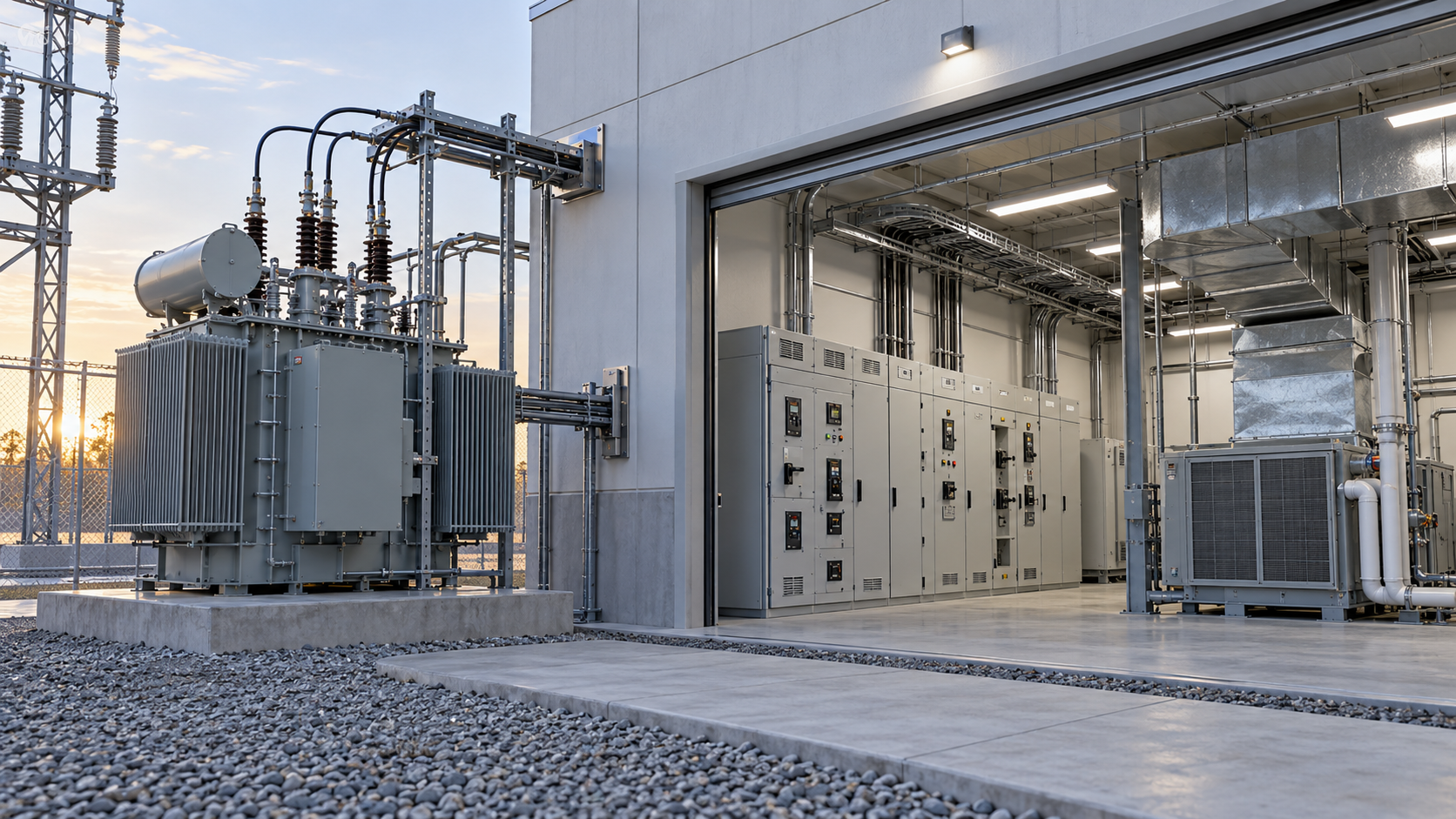
Locate station-service transformers with attention to fire separation, cable length, access, ventilation and replacement route. Zisheng Electric can review transformer design-change interfaces before civil and cable drawings are frozen.
Battery sizing should begin with the required event sequence. List continuous relay and communication loads, emergency lighting, alarms, breaker trips, breaker closing, motor-operated disconnectors and any inverter-fed loads. Apply the specified autonomy period, battery aging and temperature factors from the approved project basis rather than an assumed value.
The highest energy demand may not be the highest momentary current. A long communication load governs ampere-hours, while simultaneous breaker operations may govern voltage drop and conductor size. Check both. State the minimum terminal voltage accepted by every connected device and calculate voltage at the remote load.
Define whether chargers operate in duty/standby, parallel load sharing or independent sections. Each charger should support the agreed standing load and recovery requirement. DC boards need selective protection so a feeder fault does not remove the entire trip supply. Earth-fault monitoring, insulation supervision and alarm routing must match the station operating philosophy.
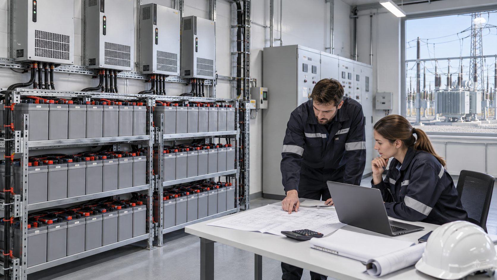
The auxiliary single-line, protection diagrams, SCADA list, panel schematics and cable schedule must use the same tag numbers and voltage levels. Differences between documents create commissioning defects. Maintain an interface register showing source, load owner, cable owner, terminal reference, signal direction and design status.
Pay special attention to transformer cooling controls, tap-changer supplies, marshalling kiosks and breaker trip circuits. Define whether local heaters remain energized during maintenance, whether trip circuits use duplicated DC sections, and how alarms are reported when one auxiliary source fails.
Automatic transfer should be described by a cause-and-effect table, not only a line on the single-line diagram. State undervoltage thresholds, delays, source-health checks, breaker interlocks, failed-transfer behavior, manual override and restoration sequence. If a diesel generator is included, define start permissives, warm-up, load steps and cooldown.
Check that transfer does not reconnect large motor loads simultaneously. HVAC, transformer fans, pumps and chargers may need staged restart. Confirm the effect on station-service transformer voltage and generator response. A black-building restart test should be planned before commissioning begins.
Battery rooms, charger panels, AC boards and station-service transformers require safe access, ventilation and replacement paths. Battery temperature influences available capacity and life, so the approved environmental range should be part of the sizing basis. Cable entries should separate redundant circuits where the project requires physical independence.
Label supply boundaries clearly. A panel that appears isolated may still receive voltage from a tie, UPS bypass or external temporary supply. Provide permanent identification and test points. Coordinate fire detection, ventilation alarms and room monitoring with the control-system scope.
Issue equipment specifications together with load schedules, single-lines, schematics, panel schedules, cable data and interface matrices. Ask suppliers to return a compliance schedule with explicit deviations. A panel general arrangement without the circuit list and short-circuit rating is not a complete technical offer.
For transformers, request guaranteed losses, impedance, cooling, terminals, dimensions and accessories. For batteries and chargers, request autonomy calculations, discharge data, charger capacity, ripple limits, alarm lists and maintenance recommendations. For AC and DC boards, request bus ratings, fault withstand, device coordination and internal wiring diagrams.
Auxiliary power commissioning should progress from source verification to individual feeders, automatic transfers and integrated functions. Confirm phase sequence, voltage, polarity, insulation, breaker operation, alarms, interlocks and SCADA indications. Test normal and failed transfer cases under controlled conditions.
For the DC system, record battery voltage, cell values, charger modes, alarm thresholds, earth-fault monitoring and trip-circuit supervision. Verify remote breaker trip and close operations using the installed cable routes. Open actions should be assigned, dated and linked to energization release.
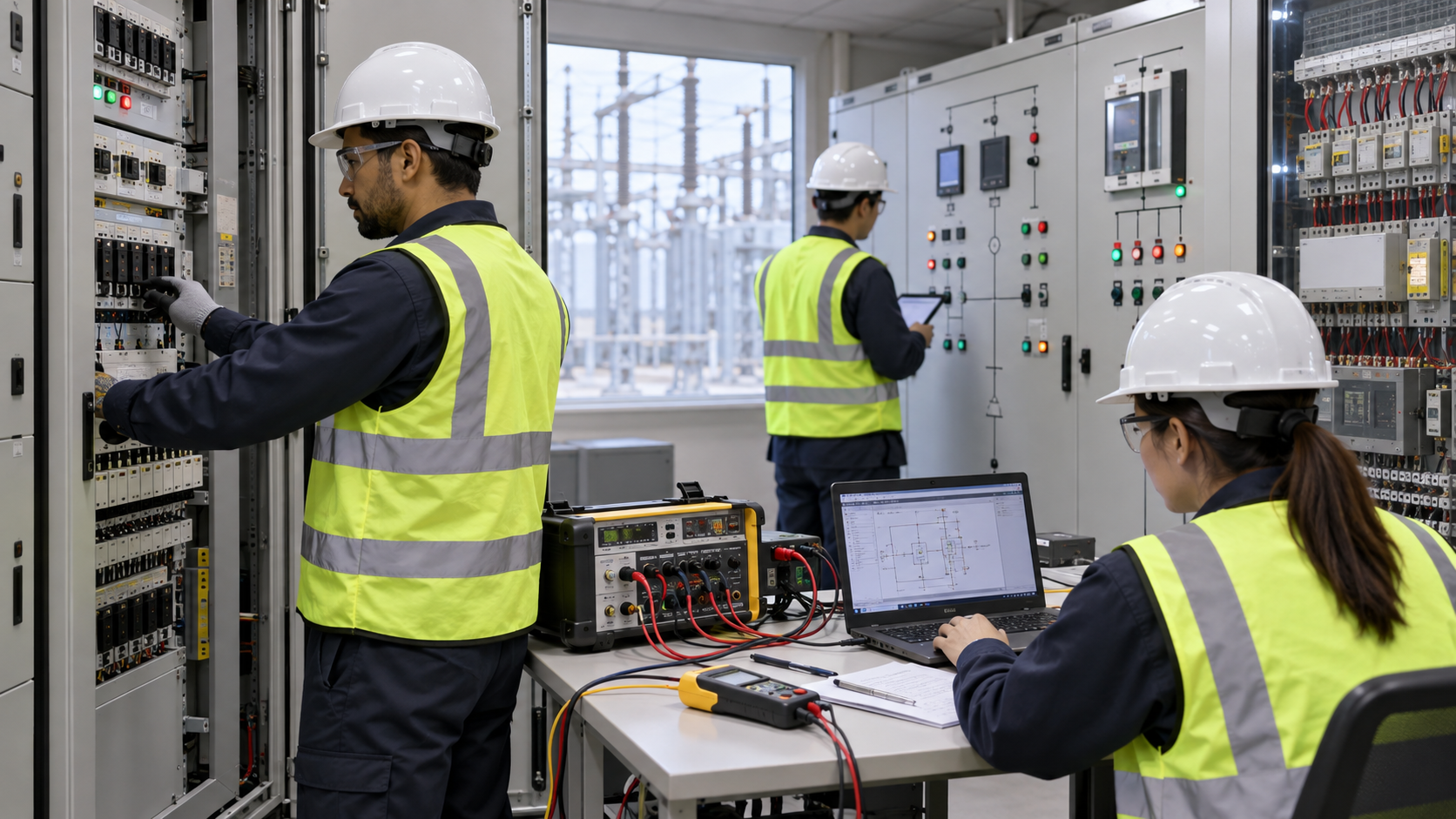
Construction power often changes as buildings, panels and permanent sources become available. A temporary supply connected without a controlled transition can defeat interlocks, energize backfeeds or leave protection without dependable power. The EPC plan should identify each temporary source, connection point, protection device, earthing arrangement and removal milestone.
Before transferring a panel to permanent power, verify phase sequence, voltage, source capacity and downstream isolation. Update labels and drawings immediately. Temporary jumpers, bypasses and lifted links should be recorded in a controlled register and removed before energization release unless the approved design specifically retains them.
Commissioning teams also need a recovery plan if an auxiliary source fails during main-equipment testing. Identify which tests can continue, which equipment must be made safe, and how DC autonomy will be protected. The plan should avoid discharging the station battery for convenience when its capacity is needed for protection.
Protection, control, cooling, lighting and communications depend on auxiliary power. If rating, transfer logic or cabling is incomplete, main equipment cannot be energized safely.
Only when the system is designed for it. Ratio, vector group, impedance, fault duty and protection must be coordinated. Many schemes use normally open ties instead.
Use a time-sequenced DC load list, required duty cycle, minimum device voltage, temperature and aging basis. Confirm both energy capacity and momentary voltage drop.
Test source failure, healthy-source confirmation, delays, breaker interlocks, failed transfer, manual control and restoration. Verify alarms and SCADA indications for every state.
Begin as soon as permanent sources, panels and wiring are safe to test. Complete essential AC/DC functions before main-circuit energization and retain signed results in the handover dossier.
Related EPC guidance includes transformer transport shock monitoring and design change control. Equipment options can be reviewed through the verified substation transformer, oil-immersed transformer and dry-type transformer pages. These interfaces should be coordinated with auxiliary supplies, alarms and commissioning records.
For an engineering review, provide the drawings, data sheets, load list, technical specification, single-line diagram, grid parameters, DC autonomy requirement, breaker coil data, environmental conditions, installation-site conditions and commissioning sequence. Identify provisional data and responsibility boundaries.
Zisheng Electric can review station-service transformers, auxiliary panels and transformer control interfaces as part of the substation auxiliary power design. “Our engineering team will review the requirements and respond to project inquiries within 24 hours.”

Plan substation arc flash study inputs for EPC projects: source fault data, transformer impedance, switchgear geometry, protection settings and as-left handover.
View details
Transformer bushing specification guide for EPC substations covering rated voltage and current, insulation levels, creepage distance, CT terminal interfaces, dimensional checks, FAT evidence and commissioning acceptance.
View details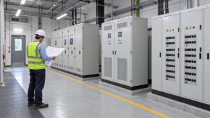
Coordinate a substation auxiliary power system for EPC projects: AC/DC loads, backup supply, charger duties, cable interfaces and acceptance records.
View details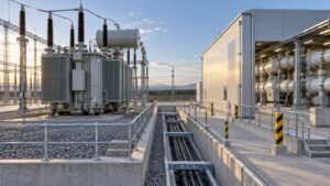
Coordinate the transformer GIS interface across terminal geometry, cable route, insulation, protection, grounding, installation and integrated testing. An EPC decision matrix identifies drawing owners, freeze dates and handover evidence.
View details