 zishengelectric




Project Partners
Phone/WhatsApp: 8619131285373
Email: info@zishengtransformer.com
Factory Headquarters: No. 118, Jingyi Street, Economic Development Zone.
Search productSearch post
Project Partners
Phone/WhatsApp: 8619131285373
Email: info@zishengtransformer.com
Factory Headquarters: No. 118, Jingyi Street, Economic Development Zone.
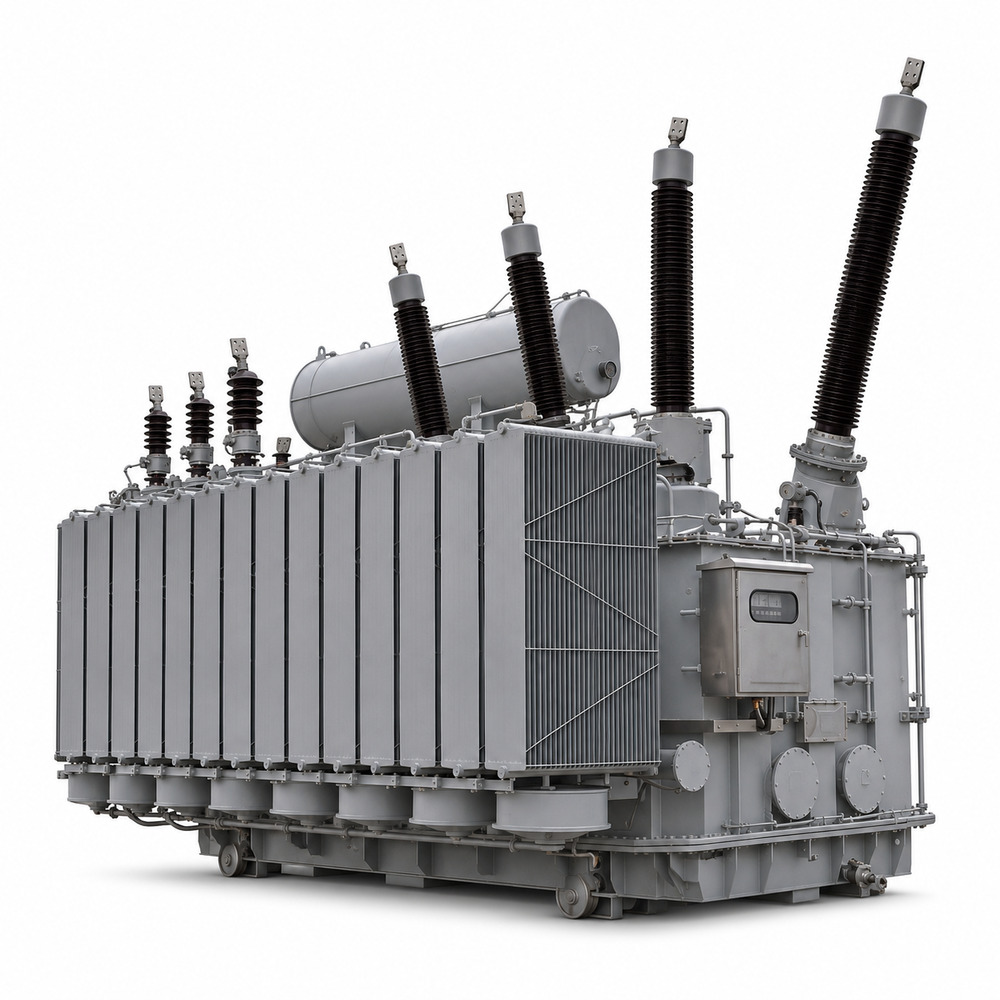
The 132kV power transformer is a three-phase oil-immersed transformer for utility substations, power plants, renewable energy and large industrial projects. It steps voltage up or down between a 132kV network and the specified medium-voltage system.
Available in customized capacities and winding configurations, it can be designed for 132/11kV, 132/33kV and other project-approved ratios. ONAN, ONAF, OFAF or OFWF cooling is selected according to the rating, operating conditions and available auxiliary services.
The transformer combines a grain-oriented electrical-steel core, an engineered winding arrangement and an oil-paper insulation system. An on-load tap changer (OLTC) can be specified when voltage regulation during operation is required.
For EPC, utility, industrial and generation projects, Zisheng coordinates impedance, vector group, insulation level, cooling-stage ratings, bushings, protection, monitoring and site interfaces with the approved technical specification.
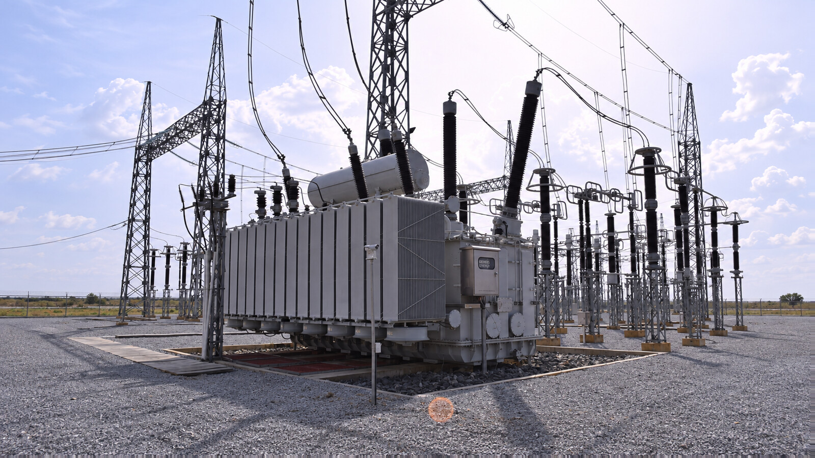
Specify the winding rated voltages, highest voltage for equipment and neutral arrangement. A nominal 132kV system voltage is not a complete insulation specification.
Agree no-load and load losses, reference conditions and temperature-rise limits at the selected cooling-stage ratings. Compare guaranteed values in the approved offer.
Review system fault level, transformer impedance, winding mechanical duty and protection clearing time together. The short-circuit withstand verification method follows the governing standard and contract.
Coordinate oil-paper insulation, bushings and terminals with the site environment. Forced cooling, OLTC and online monitoring are included only when specified.
The active part consists of the magnetic core, windings, solid insulation and internal leads. The specified grain-oriented electrical steel forms the magnetic circuit; the approved design identifies step-lap or mitred construction. Copper or aluminum conductors follow the order specification, rather than being inferred from a photograph.
The main tank contains the active part and insulating liquid. Mineral oil or a specified ester fluid must be reviewed with the insulation, sealing and thermal design. Radiators or coolers remove heat; a conservator and breather are used where required by the selected oil-preservation arrangement.
Bushings connect the windings to the external circuit. Review terminal position, current rating, air clearances, creepage and any bushing CT interfaces. The accessory schedule defines valves, lifting and jacking points, earthing terminals, pressure relief, temperature indication and control cabinets. Buchholz relay applicability depends on the oil-preservation arrangement.
ONAN means oil natural, air natural; ONAF uses natural oil circulation with forced air; OFAF uses forced oil and forced air. OFWF uses forced oil and forced water and requires a defined cooling-water supply, heat-exchanger interface and operating controls. These are design options, not four standard cooling systems installed on every unit.
State the continuous MVA rating at each cooling stage and the auxiliary supplies available at site. An OLTC adjusts the selected tapping winding during operation. Off-circuit tap changing requires isolation and de-energization. Confirm tap range, steps, regulator, drive supply and local/remote controls in the approved schedule.
| Selection item | Information required |
|---|---|
| Duty and capacity | Simultaneous load or generation profile; power factor/reactive-power range; growth and contingency duty; required MVA at each cooling stage. |
| Network connection | Single-line diagram; every winding voltage and frequency; vector group and neutral earthing; fault level and target impedance; existing nameplate/test data for parallel operation. |
| Insulation and site | Highest voltage for equipment; impulse/AC/PD requirements; bushing creepage and terminal geometry; ambient, altitude, pollution, corrosion, seismic and sound requirements. |
| Controls and logistics | Tap/control requirements, auxiliary AC/DC supplies, protection contacts and communications; foundation, oil containment, route restrictions, unloading and maintenance access. |
| Acceptance and documentation | Governing standard and edition, inspection/test plan, witness and hold points, approved drawings, report format, installation instructions and shipment release. |
An industrial park supply connects a 132kV incoming circuit to a 33kV distribution bus serving process plants and future tenants. The demand includes sustained process loads, large motor starts and changing occupancy. Transformer selection uses the simultaneous electrical demand and agreed contingency duty; installed motor nameplates alone do not determine the required MVA.
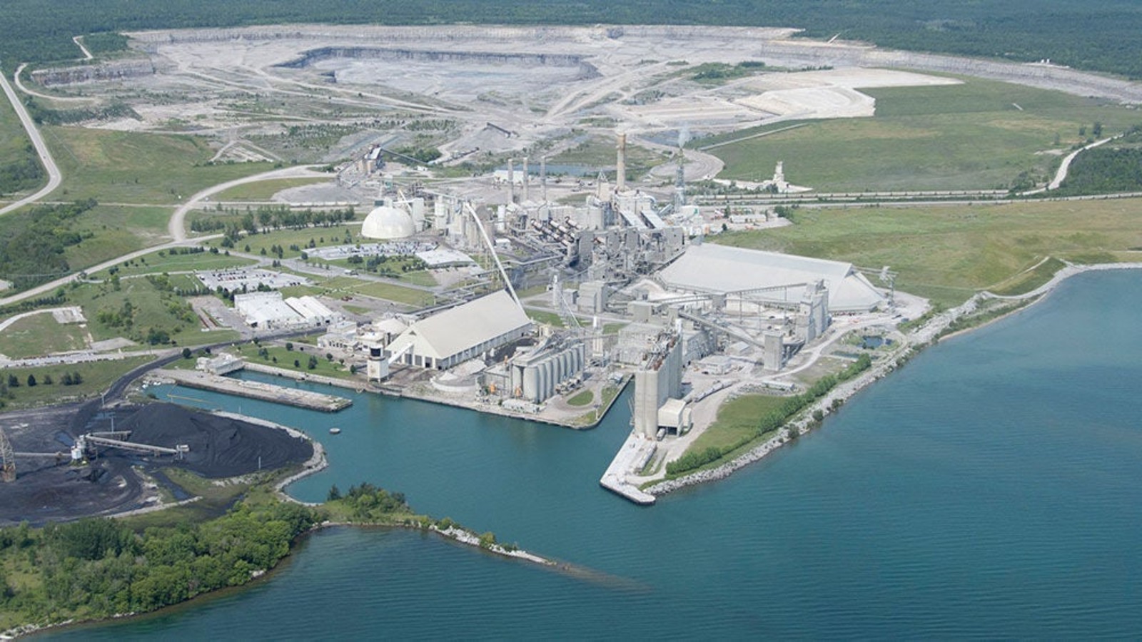
The site must accommodate the transformer bay, oil containment and future feeder works within a restricted layout. Review the motor-starting voltage dip together with network strength and transformer impedance. If a second unit will operate in parallel, coordinate ratio, vector group, tap range and impedance characteristics before ordering either transformer.
| Engineering issue | Configuration and acceptance requirement |
|---|---|
| Supply interface | 132kV/33kV, three-phase; project-approved MVA and cooling-stage ratings; confirmed neutral-earthing and protection arrangement. |
| Load behaviour | Review motor starting, power factor and any drive harmonic currents with the plant load study. Agree the permitted restart sequence after an interruption. |
| Physical constraints | Check foundation loads, bushing positions, cable/bus interfaces, maintenance clearances and delivery access on coordinated drawings. |
| Acceptance | Require serial-number-linked FAT reports and accessory/control records; inspect transport condition and prove the approved feeder and tap-control interfaces at commissioning. |
Select OLTC and forced cooling only where the voltage-regulation and loading studies require them. The final engineering package must identify auxiliary power, alarms, cooling controls and the maintenance access needed around the tank and coolers.
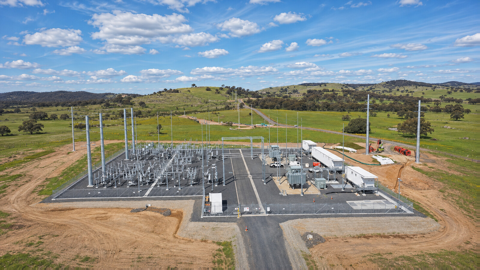
A wind-farm collector substation connects a 34.5kV collector bus to a 132kV grid. The transformer operates with variable active-power export and a defined reactive-power duty. Selection must cover the apparent-power envelope across the required power-factor range, including any specified energization or standby import duty.
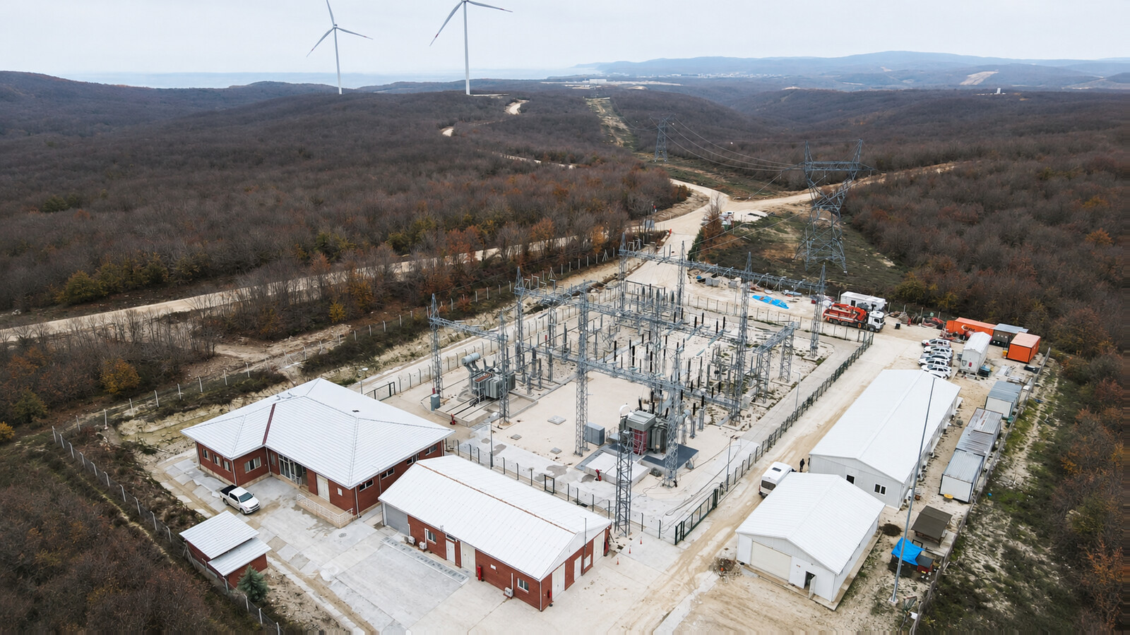
The grid-interface review must coordinate insulation levels, vector group, neutral earthing, impedance and protection with the collector network. Tap regulation must work with the plant voltage/reactive-power controller. Harmonic assessment uses the turbine/converter data and the agreed operating envelope; the transformer should not be assigned a generic harmonic tolerance without supporting design evidence.
| Engineering issue | Configuration and acceptance requirement |
|---|---|
| Voltage and power duty | 132kV/34.5kV, three-phase; approved export/reactive-power envelope and continuous ratings at each cooling stage. |
| Grid coordination | Confirm utility insulation levels, neutral connections, fault duty, surge-arrester interface and transformer protection requirements. |
| Site interfaces | Review wind, corrosion/pollution exposure, cable or overhead terminals, oil containment and road/crane access for the actual location. |
| Factory and site release | Agree dielectric, loss/impedance and control test evidence, witness points and the transport preservation plan. Complete pre-energization checks and coordinated plant-control proving before export. |
The approved datasheet and single-line diagram should distinguish transformer capability from the complete wind-farm export rating. Commissioning responsibilities must cover the transformer, collector switchgear, grid protection and plant controller interfaces.
These parameters define the 132kV product family. Final order values follow the approved technical schedule and design.
| Item | Specification |
|---|---|
| Product Type | Oil-Immersed Power Transformer |
| Rated Capacity | 10–200+ MVA, Customized |
| Number of Phases | Three Phase |
| Rated Frequency | 50Hz / 60Hz |
| HV Rated Voltage | 132kV |
| MV/LV Rated Voltage | 11kV / 13.8kV / 33kV / 34.5kV / Customized |
| Voltage Ratio | 132/11kV, 132/33kV and other approved 132kV ratios |
| Cooling Method | ONAN / ONAF / OFAF / OFWF |
| Tap Changer | OLTC / Off-Circuit Tap Changer |
| Tap Range | Typically ±10% / ±12.5% / ±15%, Customized |
| Vector Group | Dyn11 / YNd11 / YNyn0 / Customized |
| Winding Material | Copper / Aluminum |
| Insulation System | Oil-Paper Insulation |
| Insulating Medium | Mineral Oil / Ester Fluid |
| Core Material | Grain-Oriented Electrical Steel |
| Core Construction | Step-Lap / Mitred Core |
| Tank Type | Conservator / Sealed Type |
| Installation | Outdoor / Indoor |
| Temperature Rise | According to project specification |
| Impedance | Customized according to system requirements |
| Insulation Level | According to applicable standard and system voltage |
| Standards | IEC 60076 / IEEE / ANSI |
| Service Life | Designed for long-term continuous operation |
| Altitude | ≤1000m standard; higher altitude available |
| Ambient Temperature | Standard design; customized for special climates |
| Application | Voltage interface |
|---|---|
| Utility substation | 132/33kV |
| Distribution substation | 132/11kV |
| Industrial substation | 132/13.8kV |
| Renewable-energy collector | 132/34.5kV, subject to approved design |
| Customized project | 132/XXkV |
Accessories such as Buchholz relay, pressure relief, OTI/WTI, oil-level indication, valves, bushings, tap/cooling cabinets and monitoring are defined in the approved accessory schedule. RS485/Modbus, IEC 61850 and SCADA interfaces are optional project items. Testing and acceptance requirements are detailed separately below.
| Selection item | Information required |
|---|---|
| Duty and capacity | Simultaneous load or generation profile; power factor/reactive-power range; growth and contingency duty; required MVA at each cooling stage. |
| Network connection | Single-line diagram; every winding voltage and frequency; vector group and neutral earthing; fault level and target impedance; existing nameplate/test data for parallel operation. |
| Insulation and site | Highest voltage for equipment; impulse/AC/PD requirements; bushing creepage and terminal geometry; ambient, altitude, pollution, corrosion, seismic and sound requirements. |
| Controls and logistics | Tap/control requirements, auxiliary AC/DC supplies, protection contacts and communications; foundation, oil containment, route restrictions, unloading and maintenance access. |
| Acceptance and documentation | Governing standard and edition, inspection/test plan, witness and hold points, approved drawings, report format, installation instructions and shipment release. |
Specify any changes to winding material, insulating liquid, tap arrangement, cooling, terminal geometry, protection or monitoring in the enquiry. Confirm the approved scope, interfaces, guarantees and deviations before production.
Develop the shipping plan from the actual main-unit mass, dimensions, center of gravity and route survey. Review road and bridge limits, port handling, trailer or rail arrangements, unloading capacity and access to the foundation before dispatch. A large power transformer is project cargo rather than a complete unit placed in a generic wooden box.
Where the approved arrangement requires removal, identify and pack bushings, radiators, conservator, fans and instruments separately. Protect connection faces and terminals and provide a component-level packing list. Braced wooden crates, pallets or skids are selected for the detached parts and their handling loads.
The approved transport instructions define the insulating-liquid or dry-gas preservation condition, sealing, monitoring and restoration procedure. Do not assume the unit is shipped oil-filled or gas-filled. Restrain, lift and jack only at designated points, keeping loads off bushings, radiator connections and pipework.
At receipt, check identification, quantities, impact damage, leakage, seals and any specified pressure, moisture or shock-indicator records. Record discrepancies before accepting the delivery. Complete the instructed reassembly, liquid processing, electrical checks and protection proving, and resolve outstanding items before energization.
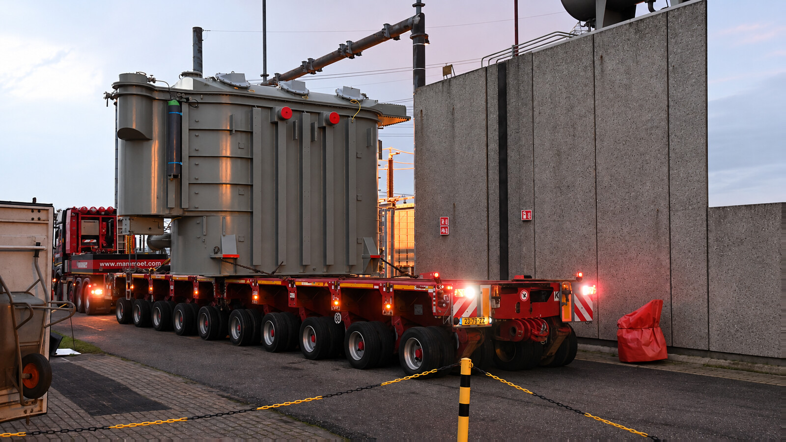
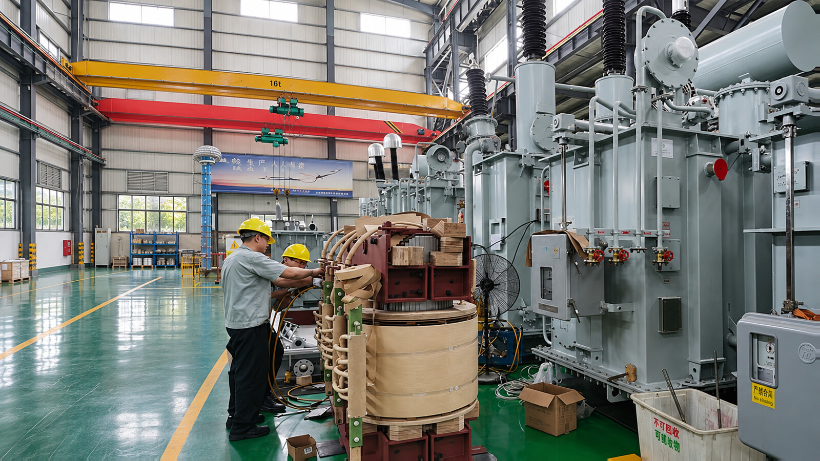
Agree an inspection and test plan before production. Manufacturing inspections address material identity, core and winding assembly, insulation clearances, drying and oil processing, tank workmanship, dimensional checks and the accessory schedule. These process checks are distinct from final electrical acceptance tests.
Specify the required material and component certificates, process records and drawing revisions. The final quality dossier should identify the transformer serial number, approved technical schedule and any accepted deviations. Establish witness access and document-review hold points before the relevant work stage.
Routine factory tests follow the governing standard and approved design. The test schedule must identify the standard and edition, test conditions, tap positions, reference temperature, acceptance criteria and report references. The website checklist does not replace the contract test programme.
| Test or check | Purpose and scope |
|---|---|
| Winding resistance, ratio and phase displacement | Verify winding connections, the specified voltage relationship and the agreed tap positions. |
| No-load loss and current | Evaluate core excitation and loss at the specified applied voltage and frequency. |
| Load loss and short-circuit impedance | Establish loss and impedance at the specified rating, tap and reference conditions. |
| Dielectric and partial-discharge requirements | Determine applied/induced, lightning-impulse and PD requirements from the highest voltage for equipment, winding/neutral insulation and applicable standard. Do not treat impulse or PD as universally optional for this voltage class. |
| Tank, tap changer, accessories and controls | Check the approved leak/tightness procedure, tap operation, auxiliary wiring, cooling controls, alarms and interlocks against the selected equipment schedule. |
| Type, special and other agreed verification | Temperature rise, sound, short-circuit withstand verification and additional diagnostics follow the applicable classification and contract. Agree test evidence, configurations and witness points explicitly. |
Factory acceptance testing (FAT) combines the agreed inspections, tests and document review. Require serial-number-linked reports, approved datasheet and general arrangement, connection/control diagrams, bushing and tap-changer documents, accessory list, inspection release, packing list and manuals. Resolve deviations before shipment; site acceptance verifies the delivered and reassembled equipment separately.
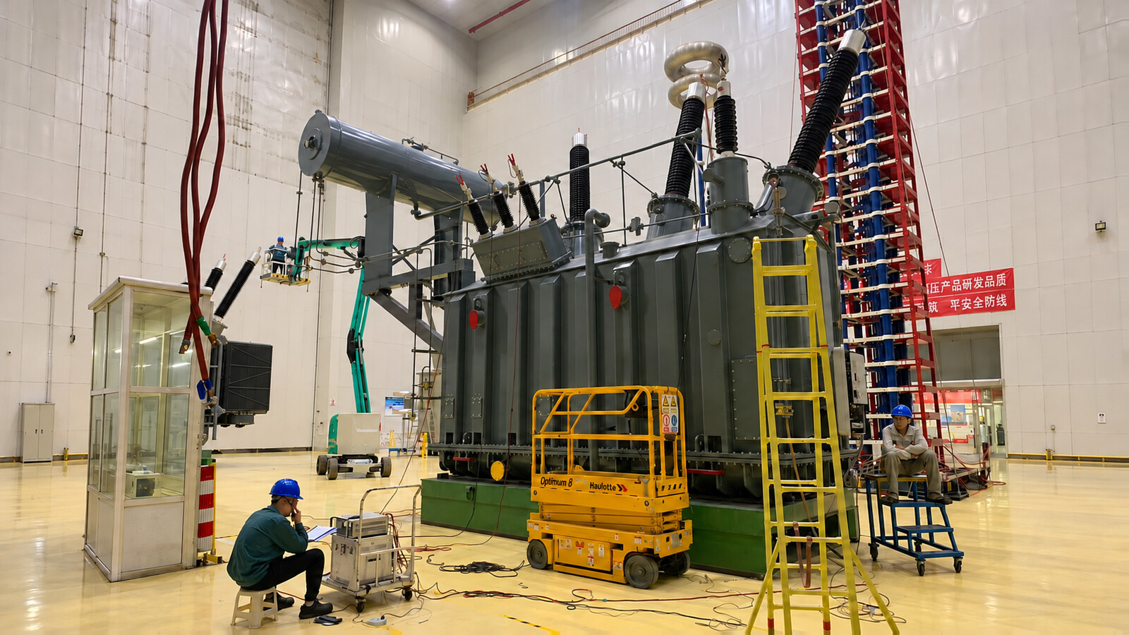
Confirm the applicable parts and editions of IEC 60076-1 and IEC 60076-3, or agreed IEEE C57 documents, in the purchase specification. A technical standard is not a product certification.
Step down a 132kV connection for regional distribution, grid reinforcement or a new load center. Review bus arrangement, contingency demand, voltage regulation and any parallel transformer interfaces.
Use an appropriately configured step-up transformer between a generating/collector voltage and the 132kV network. Define active and reactive power duty, energization conditions and the grid protection boundary.
Connect a solar, wind or hybrid collector system to a 132kV grid where the winding ratio and approved design match the duty. Include converter harmonics, reactive-power range and control coordination in the enquiry.
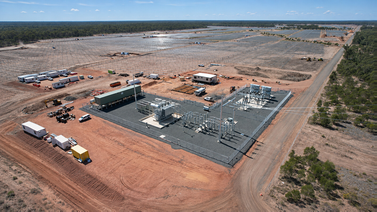
Supply major process plants, mining operations or industrial parks through a coordinated 132kV substation. Evaluate simultaneous demand, large motor starts, harmonics, fault duty and the available maintenance outage.
It is a three-phase oil-immersed power transformer with a specified 132kV network interface. The voltage designation does not state its MVA capacity. Winding rated voltage, highest voltage for equipment and insulation levels must be specified separately.
Use simultaneous load or generation demand, power factor/reactive-power range, growth, contingency duty, ambient conditions and cooling stages. The capacity range is listed once in the specification table; the ordered rating is fixed in the approved datasheet.
The 132kV design can use the listed 11kV, 13.8kV, 33kV or 34.5kV winding options where approved for the project. Specify the rating and insulation of every winding and neutral. Separate voltage-family products require their own technical review.
Specify the required rated frequency. The listed 50Hz/60Hz options are design alternatives; do not assume a transformer built for one frequency can run at the same voltage and rating on the other frequency without engineering approval.
An on-load tap changer is included only when specified. Confirm the tapping winding, range, steps, drive supply, regulator and local/remote controls. Off-circuit tap changing requires the transformer to be isolated and de-energized.
The listed ONAN, ONAF, OFAF and OFWF options are selected for the approved design. State the MVA rating at each stage, auxiliary power and controls. OFWF also requires an agreed cooling-water and heat-exchanger interface.
Copper or aluminum follows the approved order specification. Compare winding design, losses, temperature limits, mechanical duty and the agreed guarantees together; material choice alone does not establish performance.
Mineral oil or a specified ester fluid follows the approved insulation and thermal design. Confirm compatibility with solid insulation, seals, maintenance practices and the applicable project requirements.
Provide ambient temperature, altitude, pollution, humidity, salt exposure, corrosion, seismic and sound requirements. Any special design measures and their verification must be included in the technical offer rather than assumed as standard.
Use the approved accessory schedule to confirm pressure relief, temperature and oil-level indication, protection contacts and control interfaces. Buchholz relay use depends on the oil-preservation arrangement. External surge arresters and other bay equipment require a defined supply boundary.
Optional DGA, moisture, bushing, tap-changer or temperature monitoring and communications require an agreed device list, protocol, point map and auxiliary supply. A communication option does not establish complete station-level integration.
Specify the applicable IEC 60076 parts, IEEE C57 documents or other agreed standards and their editions. These standards define requirements and methods; they are not evidence that the product holds a named certification.
Agree the routine test programme for the governing standard and design, including the applicable dielectric and PD requirements. Define type, special, diagnostic and witness requirements explicitly. Do not assume every test in a general brochure is performed on every unit.
Identify the inspector, witness/hold points, notice period, document-review period and release authority in the approved inspection and test plan. Agree the scope and access before production reaches the relevant stage.
Request the approved datasheet, general arrangement and foundation loads, bushing and terminal details, connection/control diagrams, accessory schedule, serial-number-linked reports, inspection release, packing list and installation/operating instructions.
Provide the project datasheet, single-line diagram, utility requirements, grid-code interfaces and acceptance requirements with the enquiry. Record approved deviations and responsibility boundaries in the final technical schedule.
Select project-cargo transport from the actual dimensions, mass and route. Define detached parts, crates/skids, restraint points and preservation condition. At receipt, inspect damage, leakage, seals, quantities and required monitoring records before reassembly and energization checks.
Review ratio, vector group, polarity, tap positions, impedance characteristics, ratings and the network arrangement. Provide the existing unit’s nameplate and test data. Matching only voltage and MVA is insufficient.
Browse oil-immersed transformers and compare the 110kV / 115kV power transformer for a different network interface.
Use the transformer inspection and test plan and site acceptance checklist to coordinate witness points, report review and energization readiness.
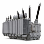 132kV Three-Phase Oil-Immersed Power Transformer
