 zishengelectric





news
News Center
Providing high-quality power to the world
Search productSearch post
news
Providing high-quality power to the world
Zisheng Electric | EPC Transformer Interface Engineering Guide
A transformer can pass every factory electrical test and still create weeks of site rework because a cable cannot reach its terminal, a busduct flange is several millimetres out of position, or a heavy cable bundle transfers mechanical load directly into a transformer bushing.
These are not transformer performance failures. They are interface failures.
At Zisheng Electric, when we review transformer packages for EPC projects, terminal arrangement is not treated as a detail to be resolved after manufacturing. The transformer GA, cable routing, busduct layout, civil works and installation sequence need to describe the same physical arrangement before the relevant drawings are released for construction.
A proper transformer cable termination review therefore goes beyond checking voltage and conductor size. It should establish where the connection is located, how the conductor approaches it, what supports the conductor, how installation tolerances will be absorbed and who owns each interface.
For rigid connections, the same discipline applies to the transformer busduct interface. A busduct should arrive at the transformer because the coordinated design puts it there – not because installers can force two misaligned components together on site.
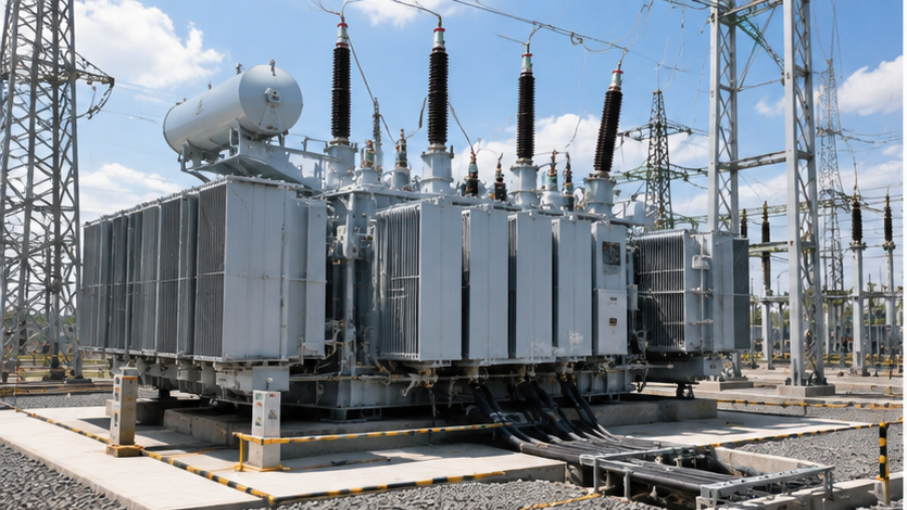
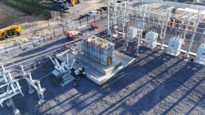
Figure 1. Transformer cable and busduct interfaces should be coordinated with the complete substation layout.
Most cable and busduct problems do not begin with an obviously incorrect drawing. They develop between drawings.
The transformer manufacturer may issue a GA showing terminal centre lines. The electrical contractor develops cable routes from the substation layout. The civil team positions trenches and openings. A busduct supplier produces fabrication drawings using an earlier transformer revision.
Individually, every drawing may look reasonable. Overlay them, and the problem appears.
A cable trench may be offset from the LV cable box. A busduct may approach from the wrong elevation. A wall opening may interfere with removable covers. The required cable bending radius may push the termination outside the available working envelope.
For this reason, EPC coordination should treat the connection as a chain: Transformer terminal -> connection hardware -> cable or busduct -> independent support -> building/civil interface -> switchgear or downstream equipment.
A mismatch anywhere in that chain can reach the transformer terminal.
| Interface Item | Common Project Problem | Possible Consequence | EPC Check |
|---|---|---|---|
| Terminal coordinates | Different drawing revisions used | Cable or busduct does not align | Freeze coordinates against approved GA |
| Cable entry direction | Route developed without terminal-box geometry | Excessive bends or installation difficulty | Review entry direction and working space |
| Cable support | Cable weight transferred to bushing/terminal | Mechanical stress and possible damage | Provide independent cable support |
| Busduct flange | Fabricated before interface dimensions are frozen | Site misalignment | Coordinate final flange position and tolerance |
| Cable trench | Civil opening based on preliminary layout | Offset route or sharp bend | Overlay civil and electrical drawings |
| Phase sequence | Different orientation assumptions | Crossing conductors or site modification | Confirm phase identification from both ends |
| Maintenance access | Connection fits but covers cannot be removed | Difficult inspection and repair | Review full service envelope |
| Installation tolerance | No adjustment provision | Force-fitting during erection | Define permitted adjustment method |
The most useful transformer connection drawing is not necessarily the one with the most dimensions. It is the one where everyone understands the same datum.
For each relevant terminal, the approved drawing should make the reference system clear. Depending on the equipment arrangement, this may include terminal centre-line coordinates, elevation, phase spacing, terminal orientation, cable-box dimensions, flange details and the transformer centre lines used as drawing references.
The viewing direction matters as well. A phase arrangement shown while looking toward the transformer can appear reversed when the installation contractor reads the same sequence from the outgoing cable side. Similar problems occur when a mirrored substation layout is developed from a standard transformer arrangement.
Do not leave this to site interpretation.
For EPC projects, confirm the HV and LV terminal sides, phase identification and sequence, terminal centre-line coordinates, finished installation elevation, cable or busduct approach direction, connection hardware supplied with the transformer, removable-cover and maintenance envelope, and drawing revision used by each interface contractor.
Once cable routing or busduct fabrication depends on these dimensions, changes should enter formal interface control rather than moving quietly through a revised GA.
A transformer bushing is an electrical insulation and current-carrying component. It should not become an improvised cable support.
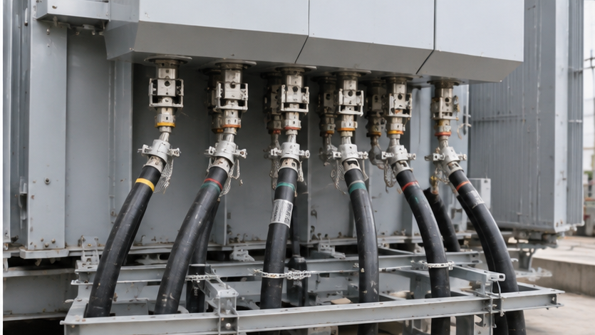
Figure 2. Cable terminations require independent support so cable weight and installation forces are not transferred to transformer terminals.
Large MV and LV cables can impose significant weight and mechanical forces, particularly where several single-core cables are installed in parallel. Cable pulling, short-radius routing, thermal expansion and poorly positioned cleats can add further loads at the termination.
The solution is not simply to make the terminal stronger. The cable system needs its own support philosophy.
Cable cleats, trays, brackets and support steel should control the conductor before it reaches the transformer connection. The final flexible portion should allow termination without transferring uncontrolled mechanical load into the bushing, palm or cable-box structure.
This becomes particularly important with large parallel LV cables. A drawing may show several conductors arriving neatly at a transformer terminal. On site, those conductors have real stiffness, bending radius and installation tolerances. If their supports are positioned incorrectly, installers may have little choice except to pull the cable into alignment. That should be identified during design review, not accepted as normal installation practice.
A cable route can fit perfectly in plan view and fail completely in section.
This is one of the most common interface problems when transformer, civil and cable drawings are reviewed separately.
The EPC team should check the actual cable path from the trench or tray to the termination, including the vertical transition. Relevant inputs include cable outside diameter, minimum bending radius, termination length, phase spacing, cleat position, trench depth, finished foundation elevation and available working space.
The cable manufacturer’s requirements should control the permitted bending radius and installation conditions. Do not estimate the bend from a schematic line.
For bottom-entry arrangements, check whether the trench opening is actually beneath the usable entry area – not merely beneath the transformer outline. Also confirm that structural beams, foundation edges or containment walls do not obstruct the bend.
Side-entry cable boxes may simplify some installations but can increase the required lateral working space. The EPC layout should consider both installation and future cable replacement. A connection that can be assembled only before the transformer is moved into its final position needs to be identified as an installation-sequence constraint.
Rigid busduct creates a different problem. A cable provides some routing flexibility. A rigid busduct provides much less.
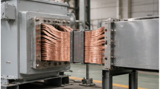
Figure 4. A flexible transformer-to-busduct connection can accommodate an approved interface design, but it does not replace dimensional coordination.
For a transformer busduct interface, the transformer manufacturer and busduct supplier should agree the connection definition before final fabrication. Depending on the design, this may include flange dimensions, phase centres, elevation, orientation, conductor arrangement, enclosure dimensions and permitted mechanical loads.
The interface drawing should also identify which supplier provides transition pieces, flexible connectors, expansion sections and connection hardware.
Do not leave a gap in responsibility between ‘Transformer supply ends here’ and ‘Busduct supply starts here.’ That gap is where site modifications appear.
The interface does not stop moving after energization.
Conductors, busduct enclosures, support steel and transformer components can change dimension as operating temperature changes. Transformer vibration also needs to be considered where a rigid connection could transmit mechanical energy into surrounding structures.
A rigid busduct route extending from a building structure to a transformer should therefore be reviewed as a system rather than as two fixed endpoints.
Ask where movement is expected, which component accommodates it, whether supports are fixed or sliding as required by the design, and whether a flexible section can accommodate movement without transferring unacceptable force to the transformer terminal.
A flexible connector installed simply because ‘we always use one here’ is not a substitute for an interface movement review.
For outdoor oil-immersed transformers, the cable route often crosses another important interface: the oil-containment system.
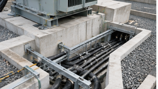
Figure 3. Cable trench geometry, foundation elevation and transformer entry points should be reviewed as one civil-electrical interface.
A cable trench that enters a transformer bund or containment area can create an unintended path for liquid if seals, drainage separation and elevations are not coordinated.
The transformer manufacturer should provide the relevant equipment interface information, while the responsible EPC disciplines determine the civil, environmental and fire-protection solution according to project requirements.
A trench should not be moved late in construction simply to make cable installation easier if doing so compromises containment or foundation design. The same applies to embedded conduits.
Once concrete has been placed, a small coordinate error can become an expensive construction problem. This is why terminal coordinates, cable entries and civil openings belong on the same interface register. This coordination should also be reviewed together with the transformer foundation interface before civil design freeze.
Mechanical alignment can be perfect while the electrical interface is wrong.
Phase sequence should be confirmed between the transformer terminals and the connected switchgear or busduct. The transformer vector group, terminal markings and project phase-identification convention should all be clear on the approved documentation.
This matters particularly where transformer layouts are mirrored, several identical transformers are installed, cables cross between rooms or trenches, bus couplers connect multiple sections, or replacement equipment must match an existing installation.
Correcting phase arrangement on site may require cable crossing or buswork modification that was never included in the original clearance study. The better approach is to catch it during drawing review.
Many interface problems are actually scope problems.
The technical drawings show a connection, but the commercial documents do not say who supplies all the parts required to make it.
Typical scope items include cable lugs, terminal palms, flexible connectors, busduct transition pieces, cable glands, gland plates, cable support brackets, earth connections, hardware, phase barriers, terminal-box space heaters and support steel.
The answer varies from project to project. That is acceptable. What is not acceptable is discovering the answer after both suppliers have shipped their equipment.
| Item | Transformer Supplier | EPC / Electrical Contractor | Busduct or Cable Supplier |
|---|---|---|---|
| Transformer terminal coordinates | Define and certify | Coordinate | Verify interface |
| Terminal hardware within transformer scope | Supply as contracted | Review | Confirm compatibility |
| Cable routing | Provide interface limits | Coordinate and approve | Develop installation arrangement |
| Cable supports and cleats | State terminal limitations where applicable | Coordinate scope | Supply/install as contracted |
| Busduct flange interface | Provide transformer-side data | Control interface | Provide busduct-side data |
| Flexible connection | Define if within equipment scope | Close responsibility gap | Supply as contracted |
| Civil opening/trench | Provide terminal/interface coordinates | Coordinate civil design | Confirm routing needs |
| Final site alignment | Verify equipment-side records | Manage survey and installation | Verify connected system |
The project-specific contract remains the controlling document. The purpose of the matrix is not to assign a universal scope – it is to expose missing scope before it becomes a site problem.
‘Approved transformer drawing’ is too broad to be a useful hold point.
Different decisions need different information. Before civil openings are finalized, the project may need terminal location and cable-entry geometry. Before busduct fabrication, the final flange interface may be required. Before cable procurement, the conductor size, termination type and number of parallel runs must be stable enough for detailed routing. Before shipment, the factory should verify the dimensions that matter to the connected equipment.
| Project Hold Point | Required Information | Main Risk if Released Too Early |
|---|---|---|
| Cable trench design freeze | Transformer position, cable entry, foundation elevation | Trench does not align |
| Cable routing release | Terminal coordinates, cable data, support concept | Bending radius or access conflict |
| Busduct fabrication release | Final flange/interface drawing | Rigid connection misalignment |
| Transformer shipment release | Dimensional inspection and final GA | Site receives different configuration |
| Equipment placement | Foundation and terminal position survey | Installation begins with unresolved mismatch |
| Energization | Completed terminations and electrical checks | Unsafe or incorrect connection |
Hold points work only when the release condition is measurable. ‘Drawing reviewed’ is not enough.
Electrical FAT and dimensional interface inspection are related but different activities.

Figure 5. Critical terminal coordinates and interface dimensions should be verified against the approved drawing before shipment.
A transformer may pass winding resistance, ratio, impedance, loss and dielectric tests while still having a connection interface that does not match the latest site arrangement.
Before shipment, the project should identify which dimensions require verification. For a cable-connected transformer, these may include terminal position, cable-box orientation, gland-plate arrangement and phase identification. For a busduct-connected transformer, flange position, elevation, phase centres and orientation may be more important. These checks complement the factory quality-control process described in our transformer manufacturing overview.
The dimensional record should identify the transformer serial number and the drawing revision against which the inspection was performed. Photographs are useful evidence. They should not replace dimensions.
Factory dimensions are only half of the interface. The other half has been constructed on site.
Before final equipment positioning, the EPC team should compare the actual foundation, trench, wall opening, busduct support or cable route against the released transformer drawings.
If a discrepancy exists, resolve it through engineering review before modifying equipment. Drilling new holes into transformer structures, cutting gland plates without approval, bending buswork or forcing terminals into position can create new mechanical, electrical and warranty problems while hiding the original interface error.
A controlled deviation is easier to manage than an undocumented site modification.
Before energization, inspect the completed transformer connection as an installed system.
Depending on the project, the final review may include phase identification, connection tightness, cable support and cleating, terminal mechanical condition, busduct alignment, earthing continuity, cable-box sealing, enclosure and gland sealing, clearance from live parts, CT and protection wiring, temperature sensors and alarms, foreign-material inspection, and approved torque records where required.
The commissioning team should also confirm that temporary installation supports, shipping restraints and temporary earthing arrangements have been addressed according to the manufacturer’s instructions and project procedure.
Any deviation accepted during construction should remain traceable in the final handover package.
A good interface process does not end when the transformer is energized.
The owner may need to replace a cable, remove a busduct section, change a transformer or expand the substation years later.
The final documentation should retain the information that makes the installed arrangement understandable: as-built transformer GA, terminal drawings, cable or busduct interface drawings, phase identification, approved deviations, relevant survey records and connection details.
Tie these documents to the transformer equipment tag and serial number where applicable.
An old preliminary GA sitting in the maintenance folder can be more dangerous than having no drawing at all because it looks authoritative while describing equipment that was never installed.
Electrical
Is the voltage, current, vector group and phase sequence confirmed?
Are the number and size of cables compatible with the available terminal arrangement?
Mechanical
Are terminal coordinates and elevations frozen?
Is cable or busduct weight independently supported?
Are permitted interface loads understood?
Installation
Can the cable achieve its required bending radius?
Can installers physically reach the connection?
Can covers, glands and barriers be installed after the transformer is positioned?
Civil
Does the trench or opening align with the final equipment?
Does the cable route conflict with the foundation or oil-containment system?
Busduct
Are flange position, phase centres, orientation and transition responsibilities agreed?
Is there an approved method for accommodating tolerances and movement?
Documentation
Are all parties working from the same GA revision?
Are interface changes controlled?
Will the final as-built package identify what was actually installed?
If several of these questions cannot yet be answered, the connection interface is probably not ready for construction release.
For an EPC transformer cable termination or transformer busduct interface review, send the transformer datasheet, single-line diagram, preliminary GA, substation layout, cable schedule or busduct data, cable-trench arrangement and relevant civil interface drawings.
For cable-connected equipment, include conductor type, size, number of runs, termination requirements and proposed entry direction.
For busduct-connected equipment, include the proposed flange/interface drawing, phase arrangement, elevation, support concept and responsibility boundary.
Zisheng Electric can support equipment-side technical coordination for oil-immersed power transformers, dry-type transformers, compact substations and related distribution equipment according to project capacity, voltage level, installation arrangement and technical specifications. Project-specific ratings and interface arrangements can also be reviewed through our custom engineering solutions.
Where the project is approaching cable-routing, civil-interface or busduct-fabrication freeze, our engineering team can review the transformer-side interface requirements and provide an initial response to project enquiries within 24 hours. For installation, commissioning and post-delivery assistance, see our Technical Support & After-Sales Service.
A stable electricity supply is essential for infrastructure development, industrial production, and commercial operations. As a core component of power distribution systems, transformers directly influence power reliability, energy efficiency, and...
View details
Oil immersed transformers are used in power transmission and distribution systems where reliable voltage conversion is required. The transformer core and windings are submerged in insulating oil, which provides both electrical insulation and heat ...
View details
Plan a transformer first-service thermal survey with safe access, representative load records, cooling checks, evidence ownership and clear EPC handover decisions.
View details
Build a transformer protection interface matrix covering CTs, relays, trips, alarms, SCADA, auxiliary power, FAT and commissioning responsibilities.
View details