 zishengelectric





news
News Center
Providing high-quality power to the world
Search productSearch post
news
Providing high-quality power to the world
A transformer oil preservation system controls how insulating oil expands, contracts and exchanges pressure with the atmosphere throughout transport, commissioning and service. For an EPC team, the system is not a minor accessory package. Its arrangement affects moisture control, oxidation, oil level indication, alarm logic, filling procedures, layout clearances and long-term maintenance. A technically complete specification must therefore connect the conservator concept to the transformer duty, ambient range, transport condition and site acceptance plan.
This guide explains how to select and coordinate a conservator, bladder or diaphragm, breather, piping, valves, gauges and protection contacts without assuming that one standard arrangement fits every project. Zisheng Electric recommends freezing the preservation philosophy before the general arrangement, auxiliary wiring schedule and commissioning procedure are approved.
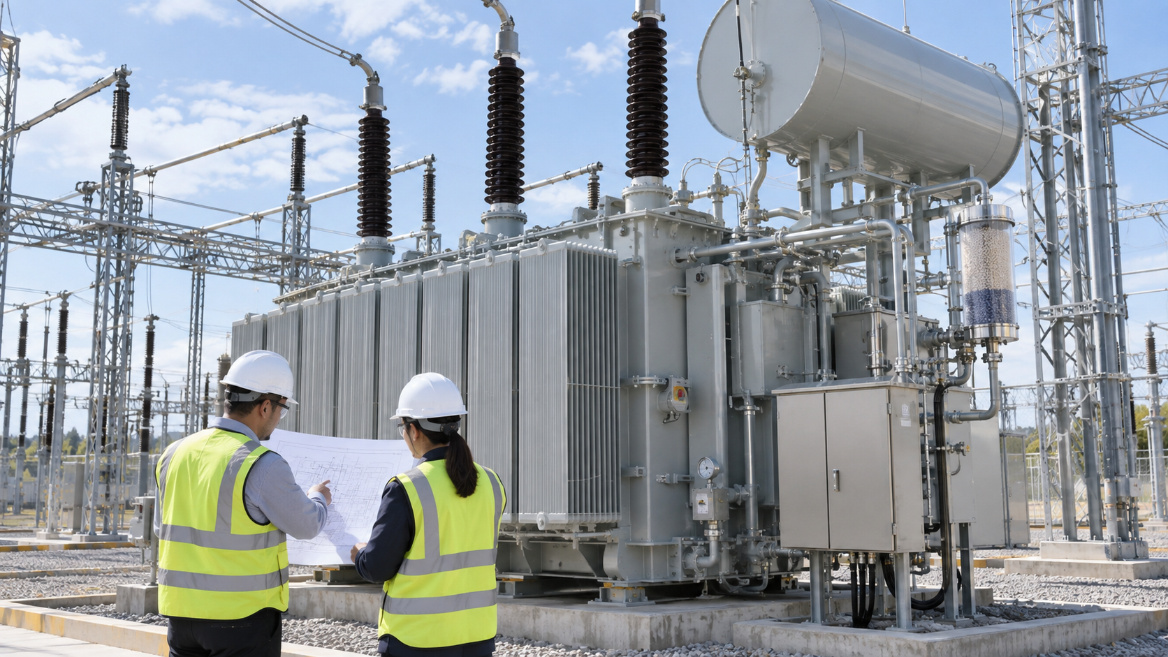
Mineral insulating oil changes volume as temperature changes. A free-breathing tank can admit humid air, while an inadequately sized expansion space can create unacceptable pressure or oil-level conditions. A preservation system provides the controlled volume and pressure path needed for the selected transformer design. Its purpose is to maintain the oil in a condition compatible with dielectric and thermal performance, not to compensate for leaks, incorrect filling or poor maintenance.
Moisture and oxygen management are central considerations. Water can reduce dielectric strength and accelerate insulation ageing, while oxidation can form acids and sludge. The preservation arrangement should limit unnecessary exposure and give operators clear evidence of abnormal oil level, loss of sealing or breather saturation. The design basis should identify the insulating liquid, maximum and minimum site temperatures, altitude, tank type, expected oil volume change and applicable project standard.
Common arrangements include a conventional conservator with a dehydrating breather, a conservator fitted with a rubber bladder or diaphragm, and sealed-tank concepts used on suitable transformer ratings and applications. These are not interchangeable labels. Each arrangement changes the air-oil boundary, maintenance tasks, alarm contacts, filling sequence and physical envelope.
In a conventional arrangement, the oil surface in the conservator can be exposed to air that passes through a dehydrating breather. The breather media must remain effective, the air path must be unobstructed, and the conservator capacity must cover the specified oil-volume range. This concept is straightforward to inspect but depends on disciplined breather maintenance and correct valve positions.
A bladder or diaphragm separates the oil from the external air space. This reduces direct contact between the oil and atmospheric moisture, but it creates additional requirements for material compatibility, installation, leak checking, venting and replacement access. The specification should define the bladder material, qualified temperature range, inspection provisions and supplier documentation. It should also state how a bladder failure or incorrect inflation condition would be recognized.
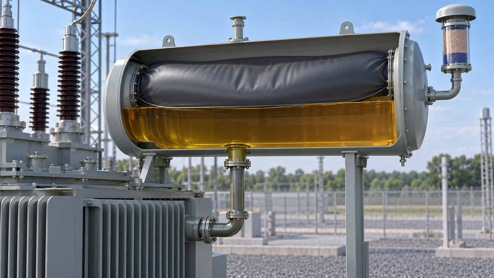
A sealed transformer may use a gas cushion or an expandable tank design, depending on rating and construction. The purchaser must not assume that a sealed concept is suitable merely because it reduces breather maintenance. Pressure limits, tank mechanical design, liquid expansion, gauges and relief provisions must be coordinated as one system. Supplier-specific limits should be reviewed against the complete ambient and loading envelope.
| Decision | Required project input | Evidence to review | Approval owner |
|---|---|---|---|
| Preservation concept | Rating, liquid type, ambient range and maintenance strategy | Supplier design description and oil-volume calculation | Transformer lead engineer |
| Conservator capacity | Total oil quantity and credible temperature range | Minimum/normal/maximum oil-level basis | Transformer supplier and EPC mechanical lead |
| Bladder or diaphragm | Liquid compatibility and site temperature | Material data, installation procedure and leak test | Owner and supplier |
| Breather arrangement | Humidity, inspection interval and access | Media type, capacity, air path and replacement method | Operations team |
| Alarm contacts | SCADA and annunciation philosophy | Contact schedule, set points and functional test record | Protection and control lead |
| Site release | Transport state, oil filling plan and commissioning sequence | Valve lineup, oil level, sealing and baseline test records | Commissioning manager |
The conservator volume should be based on the transformer’s oil quantity and the expected liquid expansion over the specified operating temperature range. A headline percentage copied from another project is not a substitute for the supplier’s calculation. The review should confirm oil levels at the defined reference temperatures and verify that the magnetic oil level indicator scale corresponds to the actual geometry and mounting orientation.
Pipework between the main tank and conservator needs a continuous, practical route for oil and gas movement. Avoid unintended air traps, unsupported long runs, inaccessible flanges and routing that conflicts with bushings, radiators, cable boxes or maintenance platforms. Isolation valves should have a clearly documented normal operating position. Where a Buchholz relay is used, the pipe gradient, orientation and accessible test features must follow the approved design and device instructions.
Mechanical interfaces must also cover lifting and transport. Conservators or pipe assemblies may be removed for shipment, so the packing list, match marks, blanking plates and reassembly procedure should be part of the supply. The site team needs defined torque values, gasket requirements, cleanliness controls and a leak-check method before oil processing begins.
A dehydrating breather should be sized for the expected breathing duty and installed where technicians can see and replace the media safely. The specification should identify the desiccant type, acceptable colour indication where applicable, oil cup or sealing arrangement, environmental protection and spare media requirement. The breather pipe must not be capped, flooded or left with transport plugs during commissioning.
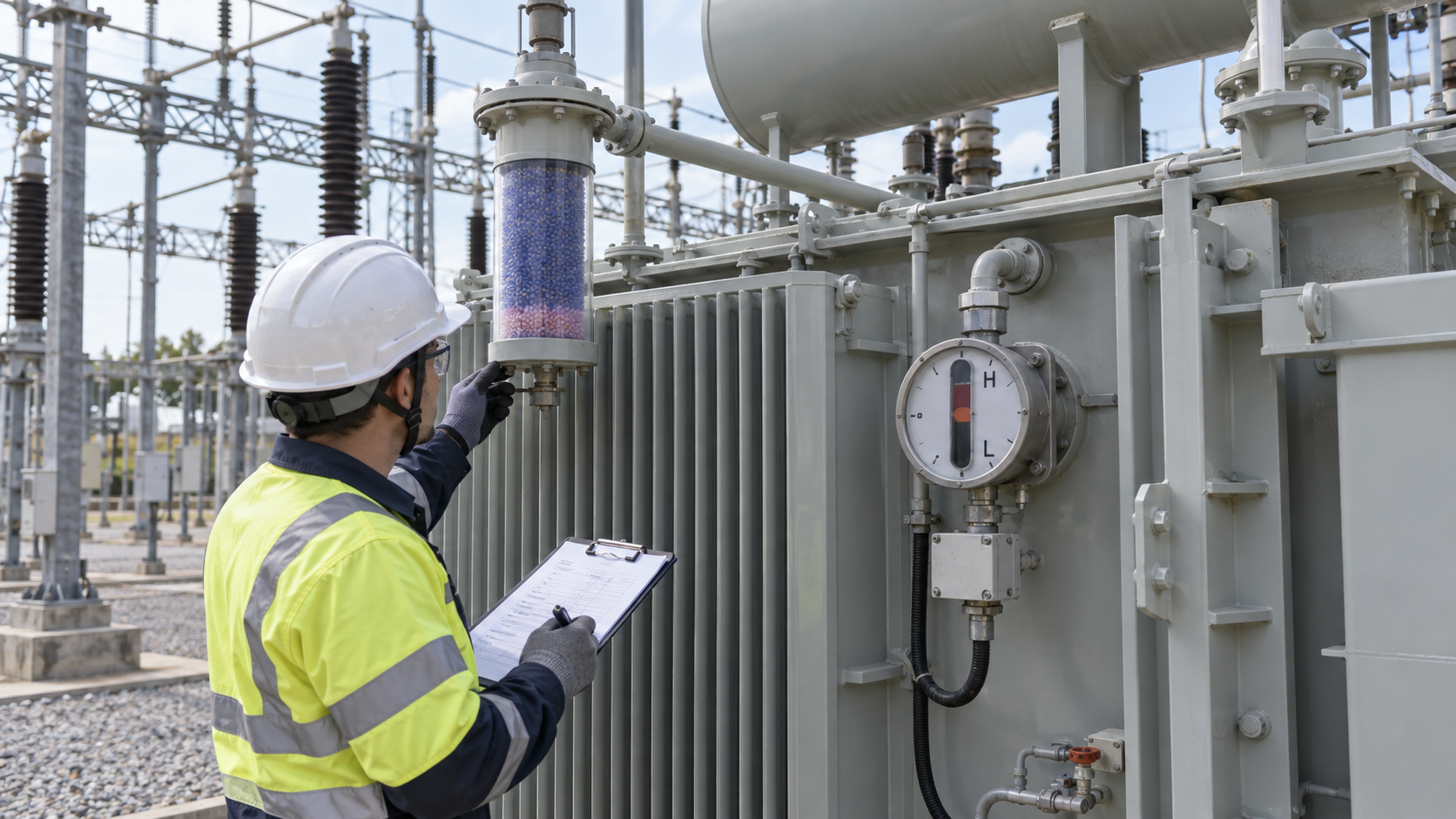
The magnetic oil level indicator should provide a readable local indication and, where specified, low- and high-level contacts. The contact logic must be reconciled with the control schematic, terminal plan, marshalling cabinet and SCADA point list. Do not leave descriptions such as “oil alarm” without identifying the device, contact state, alarm priority and test method. Contacts should be functionally checked during FAT and again after site assembly if wiring or accessories were disturbed.
The supplier submittal should include the preservation-system description, conservator drawing, calculated oil-level range, accessory data sheets, pipe and valve schedule, schematic diagrams and maintenance instructions. Bladder documentation should state material and compatibility information. Drawings should show the breather location, oil level indicator orientation, alarm terminals, drain and filling points, valve positions and required access envelopes.
Factory inspection is an opportunity to verify physical completeness and interface consistency. Check nameplates, conservator supports, flange alignment, valve tags, piping cleanliness, breather assembly, gauge indication, alarm contacts and marshalling wiring. The test record should distinguish between factory-installed parts and components removed for shipment. Routine transformer tests do not by themselves prove that every preservation accessory has been correctly assembled or functionally integrated.

IEC 60076-1 provides general requirements for power transformers, while IEC 60422 addresses supervision and maintenance guidance for mineral insulating oils in electrical equipment. Project teams should confirm the applicable editions and national adoptions through the official IEC Webstore. The transformer specification, purchase order and approved supplier documents remain the controlling project references.
The transport condition must be explicit. State whether the main tank is shipped oil-filled, partially filled or under dry gas, and identify how the conservator, bladder, breather and pipework are packed. Temporary seals, pressure readings and shock records should be checked at receipt. Any evidence of damaged pipework, loose supports, abnormal pressure or contaminated blanking surfaces should be documented before assembly.
For extended storage, align preservation actions with the project’s transformer long-term site storage plan. Maintain the specified internal condition, protect accessory openings, inspect packaging and record pressure or dew-point data where required. Storage controls are especially important when the conservator and breather are not yet connected.
During site assembly, use the approved procedure and verify internal cleanliness before opening oil circuits. Confirm bladder condition, piping slope, valve lineup, gasket installation, gauge orientation and alarm continuity. The oil filling and vacuum process should be coordinated with the approved transformer oil filling procedure; an incorrect valve position or trapped air can compromise both the filling process and subsequent indication.
Before energization, compare the actual oil level with oil temperature and the supplier’s reference curve. Inspect all preservation-system flanges and valves for leakage, verify breather condition, remove transport blanks, confirm the conservator air path, and check the normal positions of isolating valves. Test low- and high-level contacts, Buchholz alarm and trip circuits where provided, and associated SCADA indications using an approved method.
Baseline records should include photographs, oil level and temperature, valve lineup, alarm-test results, oil test certificates, final drawing revisions and outstanding punch items. Coordinate this evidence with the substation pre-energization readiness review so that preservation-system checks are not lost inside a generic mechanical checklist.
Issue the transformer data sheet with the required preservation concept, site ambient range, liquid type, maintenance constraints, alarm philosophy and documentation schedule. Ask bidders to state their proposed arrangement, conservator calculation basis, bladder material, breather capacity, alarm contacts, transport condition and exclusions. Review deviations before the general arrangement is frozen.
For a conventional outdoor application, the EPC team may begin with an oil-immersed transformer configuration. Higher-voltage substations can reference the 220kV/230kV power transformer product range, while packaged distribution projects may require interface coordination with a prefabricated substation. Product selection must still follow the approved ratings, standards and project-specific design review.
A reliable transformer oil preservation system is achieved by coordinating oil volume, atmospheric isolation, conservator geometry, breathing equipment, pipework, alarms, transport and commissioning evidence. When these items are treated as one controlled interface, the EPC team can reduce moisture risk, avoid incorrect site assembly and give the operator a maintainable system with clear baseline records.
The final handover package should also identify inspection intervals, consumable spares, approved replacement parts and escalation responsibilities.
Send the transformer rating, insulating liquid, ambient range, loading profile, site altitude, preferred preservation concept, alarm schedule and transport constraints to Zisheng Electric. Include the single-line diagram, transformer data sheet, general arrangement envelope and commissioning requirements so the engineering review can address both equipment design and site interfaces. Our engineering team will review the requirements and respond to project inquiries within 24 hours.

Build a practical substation cable interface schedule for EPC projects, covering power, control and fiber cables, terminal data, routing, scope ownership, construction release and commissioning evidence.
View details
Oil immersed transformers are used in power transmission and distribution systems where reliable voltage conversion is required. The transformer core and windings are submerged in insulating oil, which provides both electrical insulation and heat ...
View details
Power infrastructure across Saudi Arabia, the UAE, Qatar, and Oman operates under conditions that would quickly derate or destroy standard electrical equipment. In these environments, transformer failure is rarely a manufacturing defect—it is almo...
View details
In EPC projects, transformer issues rarely appear during the quotation stage. They usually become visible later — during installation, inspection, or commissioning, when changes are costly and project schedules are already under pressure. A transf...
View details