 zishengelectric





news
News Center
Providing high-quality power to the world
Search productSearch post
news
Providing high-quality power to the world
Zisheng Electric treats protection coordination as an EPC interface package rather than a collection of relay settings. A clear transformer protection interface defines what detects each abnormal condition, which device initiates the trip, which breakers open, what the control system records and how the complete chain will be tested. Establishing this logic before manufacturing prevents duplicated functions, missing contacts and late changes to panels or cables.
The transformer supplier, switchgear vendor, protection engineer, SCADA integrator and EPC electrical team often deliver different parts of the same protection chain. Their documents may be individually correct but incompatible at the terminals. The practical solution is one coordinated interface schedule supported by the single-line diagram, CT data, trip matrix, I/O list, wiring diagrams and factory test procedure.
Relay settings are an output of the system studies and equipment data. They cannot be finalized reliably until winding ratings, vector group, impedance, CT ratios and classes, earthing arrangement, inrush characteristics, overload capability and breaker clearing times are confirmed. Procurement should therefore lock the physical and logical interfaces first, while maintaining a controlled register of assumptions.
A useful interface boundary drawing shows the transformer, high- and low-voltage breakers, CTs, neutral equipment, marshalling kiosk, local control cabinet, protection panels, station DC system and SCADA gateway. Each crossing signal should have an owner, source terminal, destination terminal, voltage level, normal state and fail-safe response.
| Interface item | Design decision | Risk if unclear | Required evidence |
|---|---|---|---|
| Protection CTs | Location, ratio, class, burden, polarity and earthing point | Differential instability or inadequate fault sensitivity | CT schedule, calculations and terminal diagram |
| Mechanical protection | Alarm/trip contacts, latching and test method | Critical device not connected or wrong breaker tripped | Device list and cause-and-effect matrix |
| Trip circuits | DC voltage, coil duty, supervision and breaker targets | Trip fails or de-energizes the wrong section | Trip schematic and point-to-point test sheet |
| SCADA signals | Tag, priority, timestamp source and communication path | Ambiguous alarm or delayed incident analysis | I/O list and signal simulation record |
| Lockout and reset | Initiators, local/remote reset and reclose blocking | Unsafe restoration after an internal fault | Approved operating philosophy |
Current transformers are not interchangeable wiring points. The protection engineer must verify ratio, knee-point or accuracy requirements, secondary resistance, connected burden, lead resistance, saturation performance, polarity and earthing. The selected technical standard and utility requirements should be cited with exact editions in the project specification; they must be confirmed for each project rather than assumed.
The physical CT locations determine the protected zone. A bushing CT can include the transformer lead in the zone, while switchgear CTs may extend protection across cables or bus connections. The single-line diagram and protection schematic should clearly show the boundaries. Software compensation for transformer ratio and phase displacement must agree with the actual vector group and relay configuration.
Unused CT cores, test links and shorting arrangements require deliberate treatment. A CT secondary must never be left open while primary current flows. Test blocks should allow safe injection and isolation without disturbing unrelated circuits. Terminal labels need to match the drawings and relay database.

Restricted earth fault protection depends on the winding earthing arrangement and the relationship between phase CTs and the neutral CT. Confirm whether the neutral CT is supplied with the transformer, neutral earthing equipment or switchgear package. State mounting dimensions, insulation level, ratio, class, terminals and cable responsibility. A missing neutral-CT interface is difficult to correct after busduct, cable boxes and foundations are complete.
For associated equipment selection, project teams can review Zisheng Electric’s 132–138 kV power transformer range and 220–230 kV power transformer range; final CT and protection requirements must be based on the actual network study and purchase specification.
Electrical relays use CT, VT and digital inputs to detect current, voltage and frequency conditions. Transformer-mounted mechanical devices detect physical conditions such as gas accumulation, sudden oil movement, oil level, pressure or temperature. Both groups can initiate alarms or trips, but they have different testing methods and failure modes.
The accessory schedule should list each supplied device, number and type of contacts, contact rating, normal state, terminal numbers, alarm stage, trip stage and reset method. Generic labels such as “temperature alarm” are not enough if there are separate winding and oil indicators, multiple cooling groups or redundant sensors.
Condition data used for asset monitoring should be coordinated with protective actions. Zisheng Electric’s guide to the transformer condition-monitoring interface explains the distinction between measurements, communications and alarms. Protection trips should remain deterministic even if a monitoring server or network connection is unavailable.
A cause-and-effect matrix converts the protection philosophy into testable actions. Each row is a cause; each column identifies alarms, breaker trips, lockout operation, cooling response, SCADA indication and restoration conditions. The matrix should use the same device numbers and breaker names as the single-line and wiring diagrams.
This example is illustrative only. It is not a relay-setting recommendation or a record of a real project.
| Cause | Local alarm | Trip action | Lockout | SCADA event | Reset |
|---|---|---|---|---|---|
| Transformer differential operate | Yes | HV and LV breakers | Yes | High priority, time stamped | Authorized local reset after investigation |
| Oil temperature high, stage 1 | Yes | None | No | Alarm | Automatic when temperature recovers |
| Oil temperature high, stage 2 | Yes | Project-defined | Project-defined | High priority | According to approved philosophy |
| Cooling group failure | Yes | None initially | No | Alarm and unavailable capacity flag | After cooling restoration |
Terms such as “trip both sides” should be replaced by exact breaker identifiers. If the transformer feeds a ring bus, breaker-and-a-half arrangement or multiple low-voltage incomers, the required isolation path may include more devices than two winding breakers. The matrix must also specify whether a bus coupler opens and whether automatic transfer or reclosing is blocked.
The trip schematic should state DC supply voltage and range, trip coil current, contact interrupting rating, fuse or miniature circuit-breaker allocation, trip-circuit supervision and redundant channel philosophy. If two protection groups are required, define whether they use separate CT cores, DC feeds, relay panels and breaker coils.
Fail-safe design does not mean that every loss of auxiliary power should trip the transformer. It means the response to a wiring fault or supply failure is deliberately selected, documented and alarmed. Normally closed and normally open contacts must be chosen according to supervision needs and the receiving equipment. The supplier’s contact ratings should be checked against the actual inductive DC duty; interposing relays may be required.
Lockout relays require special attention. Identify all initiators, all tripped breakers, reclose blocking, local indication, reset authority and reset location. A remote reset command should not be added by convenience if the owner’s safety philosophy requires physical inspection.
Winding neutral treatment determines earth-fault magnitude and the usable protection functions. The protection engineer needs the neutral earthing resistor or reactor rating, continuous and short-time current, duration, insulation level and CT details. Ownership of the neutral package and its temperature or failure alarms should be explicit.
The grounding conductor arrangement, tank bonding, surge arrester earth paths and control-cable screen practice must be coordinated with the civil and substation earthing design. The related transformer earthing interface guide provides a structured handover between transformer, civil and electrical scopes.

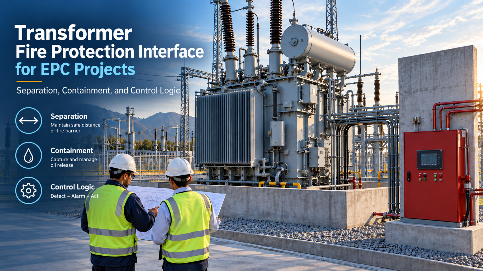
Fire detection and suppression should receive confirmed transformer trip or isolation status where the fire strategy requires it. Conversely, a fire-system signal should only trip breakers when the approved cause-and-effect establishes the action. Refer to the project-specific fire study and Zisheng Electric’s transformer fire-protection interface for adjacent coordination points.
The I/O list should distinguish hardwired trips, hardwired alarms, serial data and engineering values. Critical protection trips often require hardwired paths even when the relay also communicates over a substation network. The project must define protocol, redundancy, time synchronization, event resolution, tag naming, quality flags and cyber-security responsibilities.
Group alarms can reduce points but weaken diagnostics. A single “transformer trouble” signal may not tell operators whether a fan failed, oil level dropped or a cabinet heater supply was lost. Decide which signals require individual SCADA tags based on operational response, not only spare I/O count.
Protection relay time, SCADA time and disturbance-record time should have a common synchronization philosophy. During a fault investigation, inconsistent clocks can make the sequence of events misleading. Confirm the time source, loss-of-sync alarm and retained accuracy.
Protection interfaces change as transformer data, switchgear drawings and studies mature. The document register should establish planned dates and dependencies for the single-line, CT schedule, protection schematic, relay-setting file, I/O list, cause-and-effect matrix, cable schedule, terminal diagram, test procedure and as-built package.
Each revision should state the change and its downstream impact. A revised CT ratio may affect settings, relay files, labels, test sheets and SCADA scaling. The EPC team should not close the comment merely because one drawing was updated. Zisheng Electric’s transformer inspection and test plan guidance can help connect document approval to witness and hold points.
Transformer FAT confirms the transformer and its supplied devices. Panel FAT confirms relay logic and panel wiring. Integrated or simulated testing is needed to prove the interface between packages. The test plan should distinguish these levels and identify which party supplies injection equipment, temporary cables, test switches and approved settings.
Site tests should verify installed cable cores, grounding, breaker operations and communication paths. Secondary injection alone does not prove primary CT polarity or the complete trip circuit. Where the project requires primary injection, stability testing or end-to-end testing, state the method and acceptance criteria before mobilization.
The interface also extends to the switching equipment. Zisheng Electric’s 3–10 kV medium-voltage switchgear page shows a relevant equipment category; breaker ratings, trip coils, CTs and panel logic must be selected against the project studies.
A robust transformer protection interface review needs the single-line diagram, transformer data sheet, CT and VT schedules, earthing philosophy, fault-study results, protection philosophy, breaker data, DC schematic, I/O list, cause-and-effect matrix, communication architecture and applicable utility requirements. Unconfirmed items should remain clearly identified as open points rather than being hidden behind “vendor standard.”
Please send your drawings, data sheets, protection studies, relay requirements, I/O list, technical specification and site interface conditions. Zisheng Electric can review the boundaries among the transformer, protection panels, switchgear and control system before they become site changes. Our engineering team will review the requirements and respond to project inquiries within 24 hours.

Transformer vector group selection guide for EPC substations covering phase shift, grounding, zero-sequence behavior, protection, parallel operation, FAT and site phasing.
View details
Coordinate transformer fire protection for EPC projects: separation, oil containment, drainage, detection, suppression, control logic, FAT and site testing.
View details
In EPC projects, a transformer room must be designed as an operating space, not just a rectangle around the tank. Zisheng Electric engineers explain essential layout considerations including safety clearances, ventilation, lifting routes, and main...
View details
Build a transformer protection interface matrix covering CTs, relays, trips, alarms, SCADA, auxiliary power, FAT and commissioning responsibilities.
View details