 zishengelectric





news
News Center
Providing high-quality power to the world
Search productSearch post
news
Providing high-quality power to the world
Oil immersed transformers are used in power transmission and distribution systems where reliable voltage conversion is required. The transformer core and windings are submerged in insulating oil, which provides both electrical insulation and heat dissipation. These transformers are installed in utility substations, industrial plants, renewable energy projects, and infrastructure developments.
For EPC contractors and project owners, selecting a manufacturer involves more than comparing equipment specifications. It requires evaluating production capability, engineering support, quality control procedures, and export experience. Zisheng Electric provides oil immersed transformer manufacturing services for international projects, with customization based on project voltage levels, capacity requirements, installation conditions, and applicable standards.
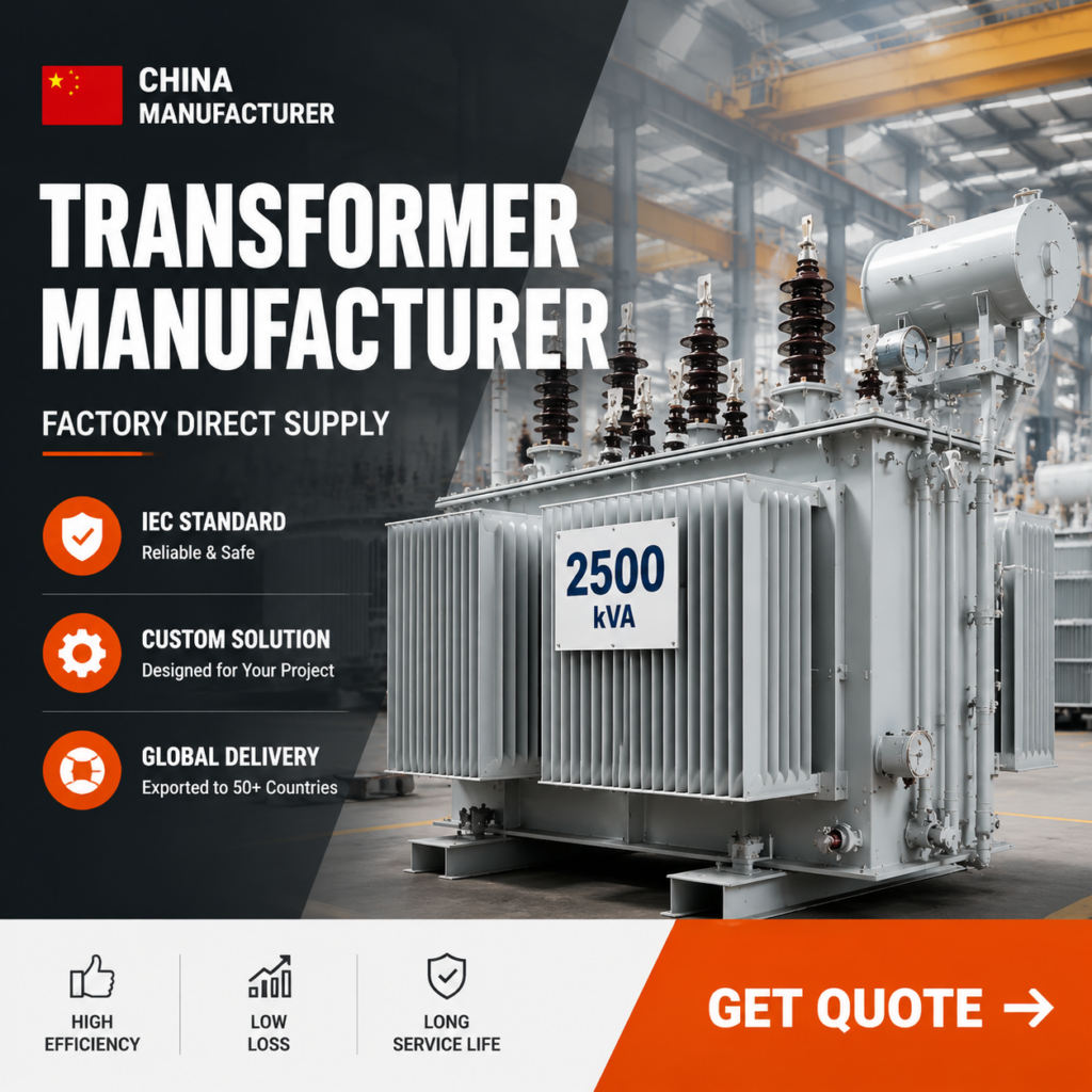
The following table shows standard parameters for our commonly supplied oil immersed distribution transformers. These values serve as reference points; actual specifications are configured according to project requirements.
| Parameter | Standard Range |
|---|---|
| Rated Power | 50 kVA – 5,000 kVA |
| Primary Voltage | 6 kV, 10 kV, 11 kV, 13.8 kV, 20 kV, 33 kV |
| Secondary Voltage | 0.4 kV, 0.415 kV, 0.69 kV |
| Frequency | 50 Hz / 60 Hz |
| Vector Group | Dyn11, Yyn0, YNd11 |
| Cooling Method | ONAN (Oil Natural Air Natural) |
| Tapping Range | ±2×2.5%, ±5% (Off-circuit or On-load) |
| Insulation Class | A Class (105°C oil temperature rise) |
| Winding Material | Copper or Aluminum (per specification) |
| Core Material | Grain-oriented silicon steel (high-permeability grades) |
| Tank Type | Corrugated fin wall or panel-type radiator |
| Applicable Standard | IEC 60076, customer-specific standards |
No-Load Loss Reference Values (11 kV, Copper Winding, ONAN):
| Rated Power (kVA) | Typical No-Load Loss (W) | Typical Load Loss at 75°C (W) |
|---|---|---|
| 100 | 320 | 1,650 |
| 200 | 540 | 2,800 |
| 315 | 760 | 3,900 |
| 500 | 1,080 | 5,600 |
| 800 | 1,540 | 7,800 |
| 1,000 | 1,800 | 9,200 |
| 1,600 | 2,600 | 13,500 |
| 2,000 | 3,100 | 16,200 |
Above values are indicative. Actual losses depend on core material grade, winding design, and customer specifications. Efficiency levels can be configured to meet local regulations.
We manufacture oil immersed transformers in multiple configurations to suit different applications:
The following images show key production stages at our manufacturing facility. These photographs were taken during routine production runs.
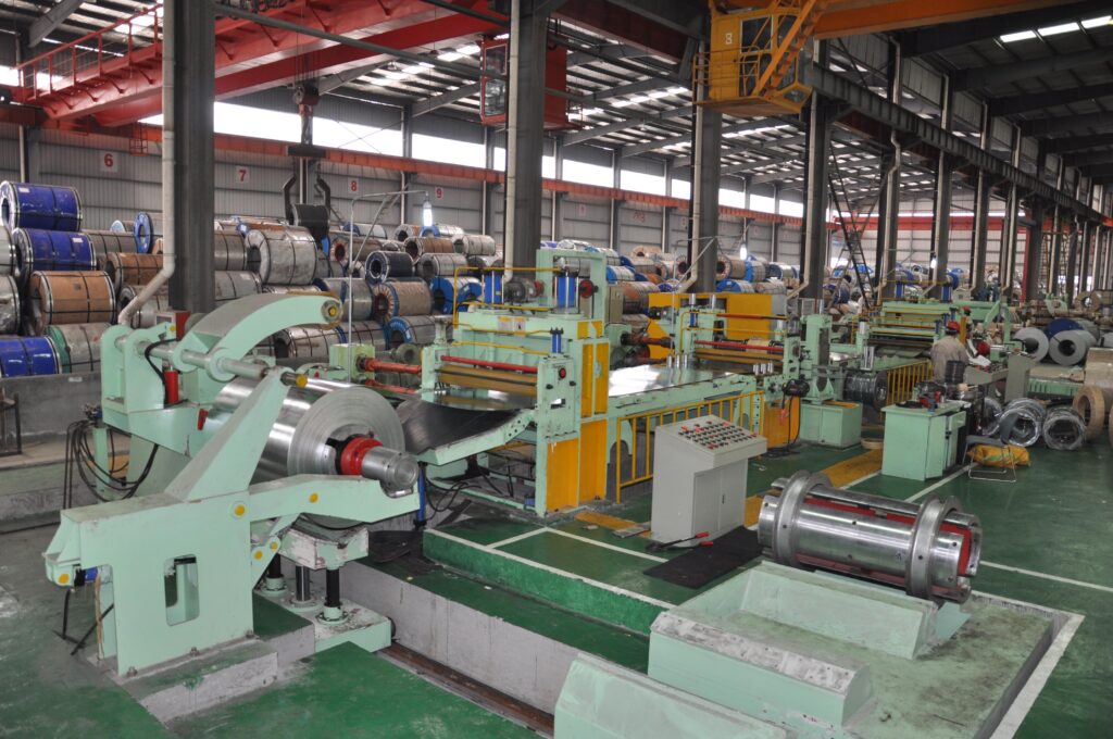
Figure 1: CNC silicon steel slitting line. Core laminations are cut with controlled burr height to minimize inter-laminar losses.
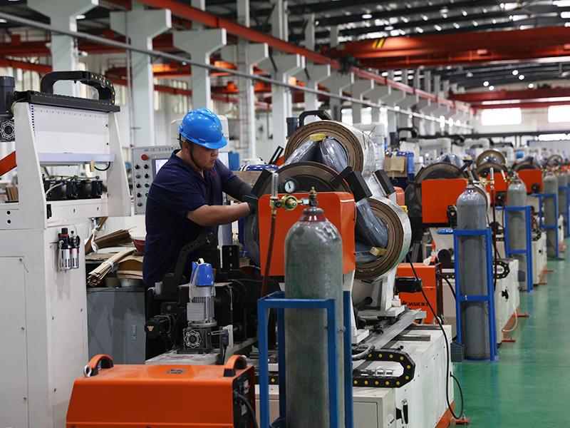
Figure 2: LV coil winding station. Winding tension is mechanically controlled to maintain consistent turn geometry.
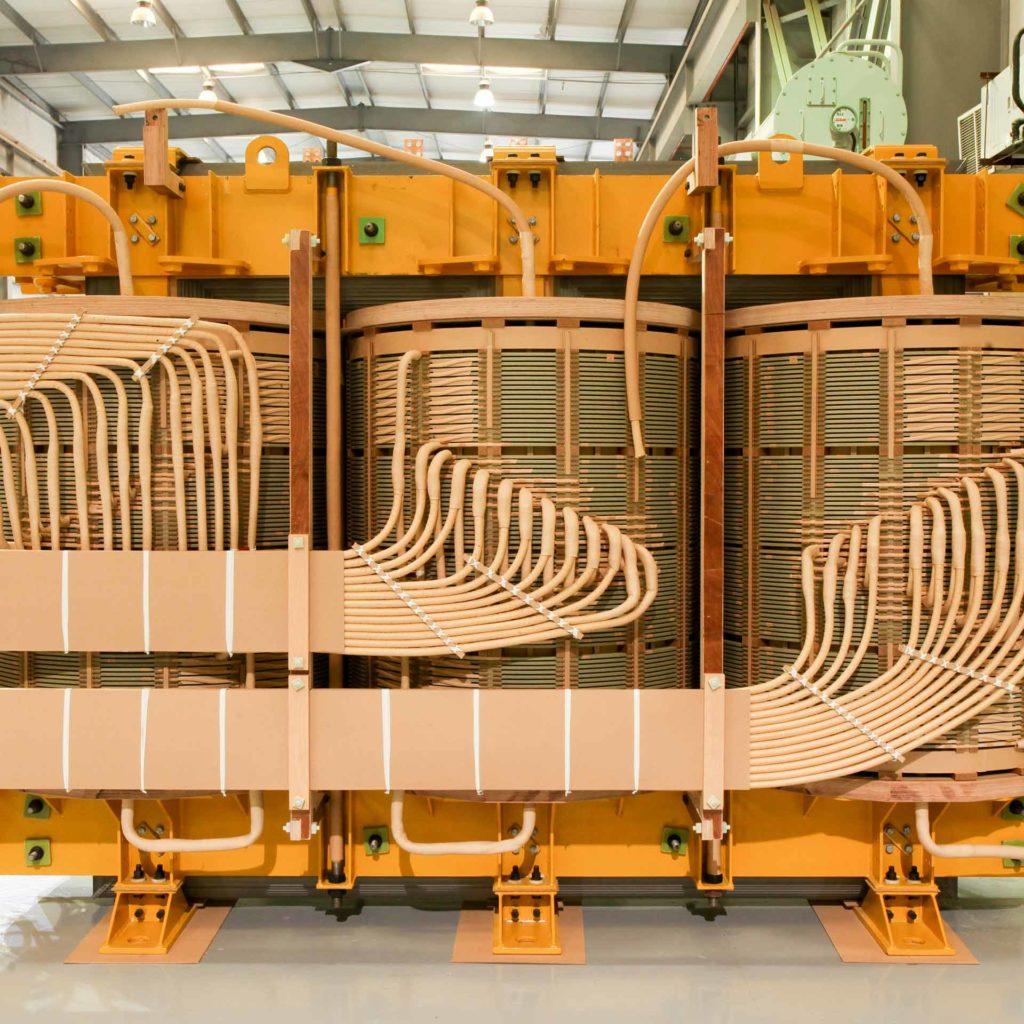
Figure 3: Core and coil assembly. The active part is prepared for insertion into the tank prior to vacuum drying.
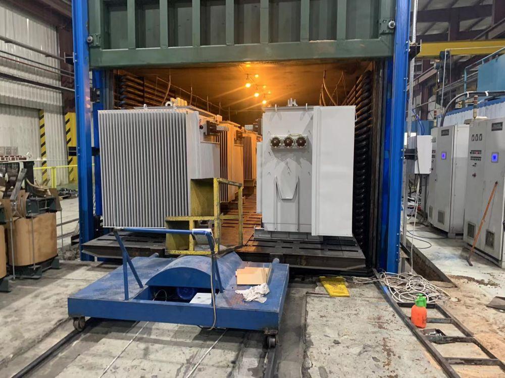
Figure 4: Vapor-phase vacuum drying chamber. Active parts are processed to remove moisture from cellulose insulation materials.
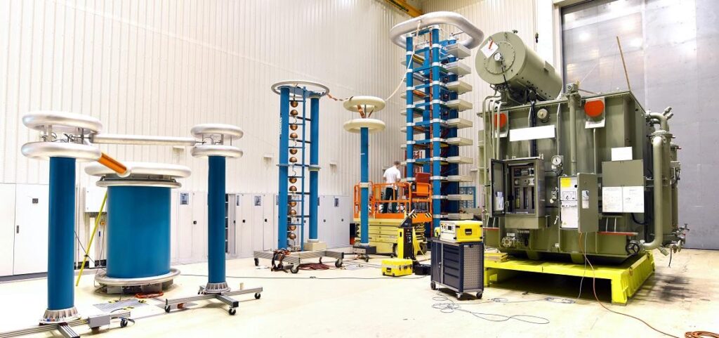
Figure 5: Routine test bay. Each transformer undergoes voltage ratio, winding resistance, insulation resistance, and applied voltage testing before release.
Project Case: Distribution Network Upgrade, Southeast Asia
Project Case: Mining Facility Power Supply, Africa
Our internal quality management covers four primary stages:
Material Receiving Inspection
In-Process Control
Final Routine Testing (Every Unit)
Pre-Shipment Inspection
Zisheng has been producing oil immersed transformers for over 20 years. During this period, the factory has supplied transformers for:
Export markets served include countries in Southeast Asia, Africa, the Middle East, and South America. Our factory team understands the documentation, testing, and shipping requirements typical of international procurement.
For EPC projects, transformer procurement typically involves several stages:
What is the typical lead time for an order?
Lead time depends on order quantity and specification complexity. Standard distribution transformers (up to 1,000 kVA) are typically produced within 8–12 weeks from order confirmation. Larger units or highly customized designs may require 14–18 weeks. A firm schedule is provided at contract stage.
Can you supply transformers with copper or aluminum windings?
We manufacture both copper-wound and aluminum-wound transformers. The winding material affects cost, weight, and certain electrical characteristics. We produce according to the material specified in the project’s technical requirements.
What testing documentation do you provide?
Every transformer ships with a routine test report containing measured values for all standard tests: ratio, resistance, losses, impedance, and dielectric withstand. Type test certificates for the relevant design family can be provided upon request.
Do you manufacture transformers with on-load tap changers?
Yes. For transformers above 500 kVA where voltage regulation under load is required, we can integrate on-load tap changers (OLTC) according to project specifications. Off-circuit tap changers remain standard for smaller distribution units.
Can you provide transformers with natural ester fluid instead of mineral oil?
Yes. Natural ester-filled transformers are available for projects with environmental sensitivity or elevated fire safety requirements. The fluid type must be specified during the design stage, as it affects internal clearances and thermal calculations.
Contact our engineering team with your project specifications for a technical review and quotation.
Request Technical Consultation →
Explore other product lines:
A distribution transformer isn't a commodity you grab off a shelf. Pick the wrong one, and you're looking at nuisance tripping, early failures, or an expensive piece of gear that never runs efficiently. At Zisheng Electric, we've been on the recei...
View details
In EPC projects, transformer issues rarely appear during the quotation stage. They usually become visible later — during installation, inspection, or commissioning, when changes are costly and project schedules are already under pressure. A transf...
View details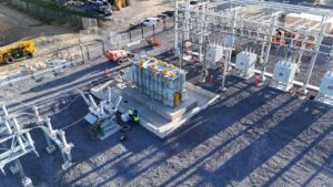
A stable electricity supply is essential for infrastructure development, industrial production, and commercial operations. As a core component of power distribution systems, transformers directly influence power reliability, energy efficiency, and...
View details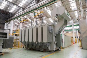
Factory-Direct Transformer Supply for Global EPC Projects For an EPC contractor, choosing a transformer supplier is rarely just about line items on a datasheet. The manufacturer standing behind the equipment has a direct bearing on how smoothly de...
View details