 zishengelectric




Project Partners
Phone/WhatsApp: 8619131285373
Email: info@zishengtransformer.com
Factory Headquarters: No. 118, Jingyi Street, Economic Development Zone.
Search productSearch post
Project Partners
Phone/WhatsApp: 8619131285373
Email: info@zishengtransformer.com
Factory Headquarters: No. 118, Jingyi Street, Economic Development Zone.
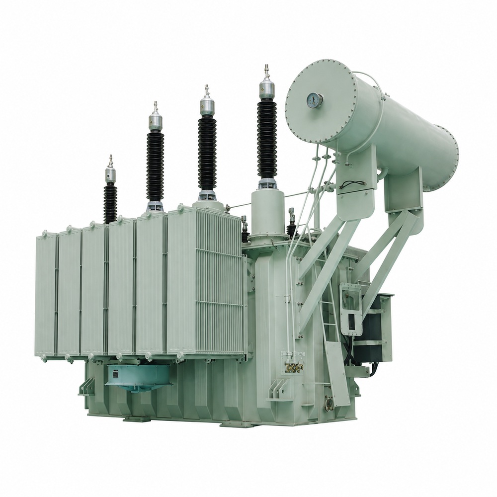
The 110kV / 115kV Power Transformer is a three-phase, high-voltage oil-immersed transformer designed for power transmission, substation and large-scale industrial applications.
It is used to step up or step down electrical energy between high-voltage transmission networks and medium-voltage systems. Rated capacity, voltage ratio, impedance, vector group, tap range, cooling system and insulation level are selected for the project requirements and installation conditions.
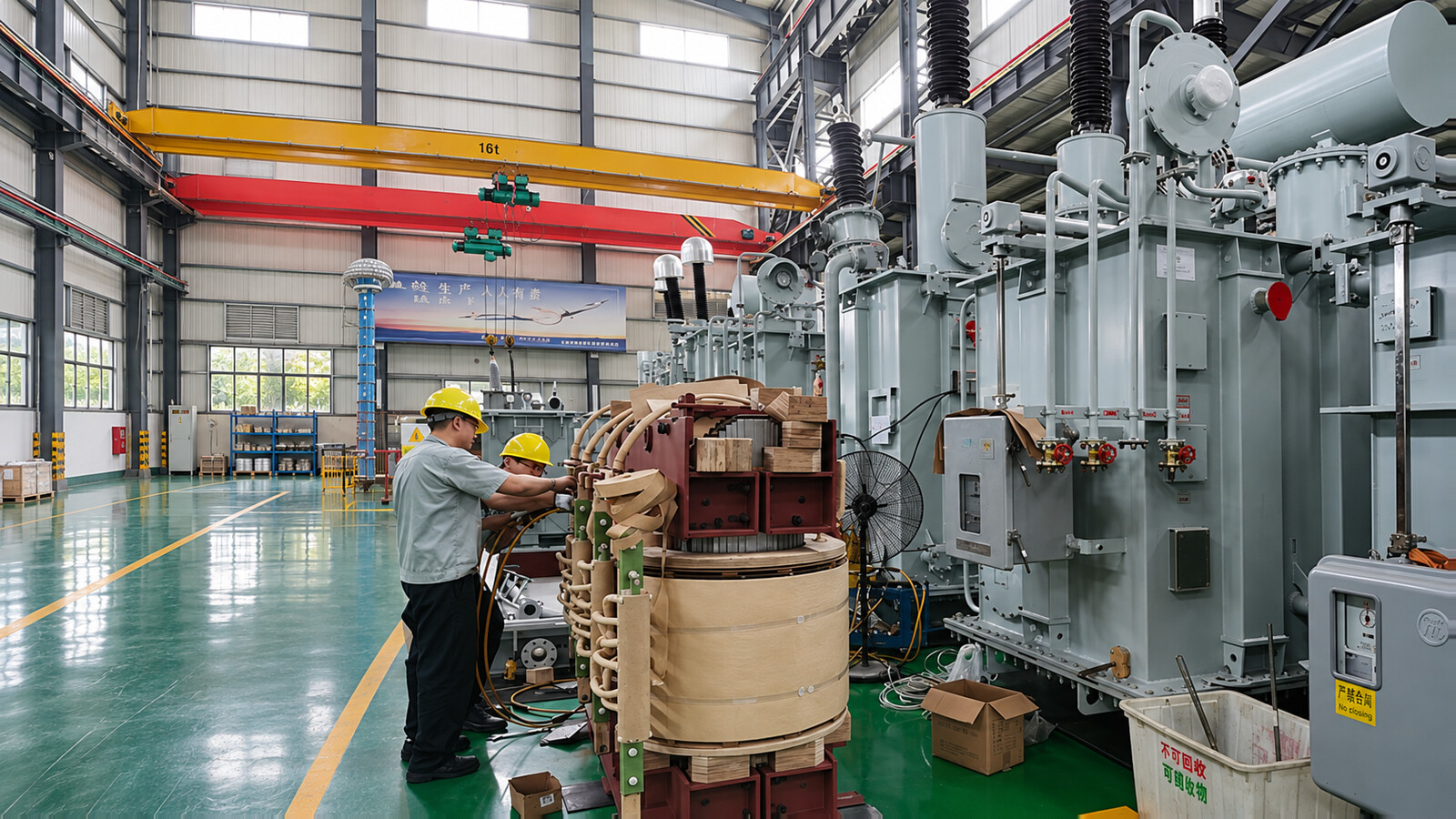
The active assembly combines the magnetic core, insulated windings, leads and supporting structures inside an oil-filled tank. Core material, copper or aluminum windings, insulation clearances and mechanical bracing are selected for the agreed loss, dielectric, thermal and short-circuit requirements. Final material grades and construction details follow the approved design.
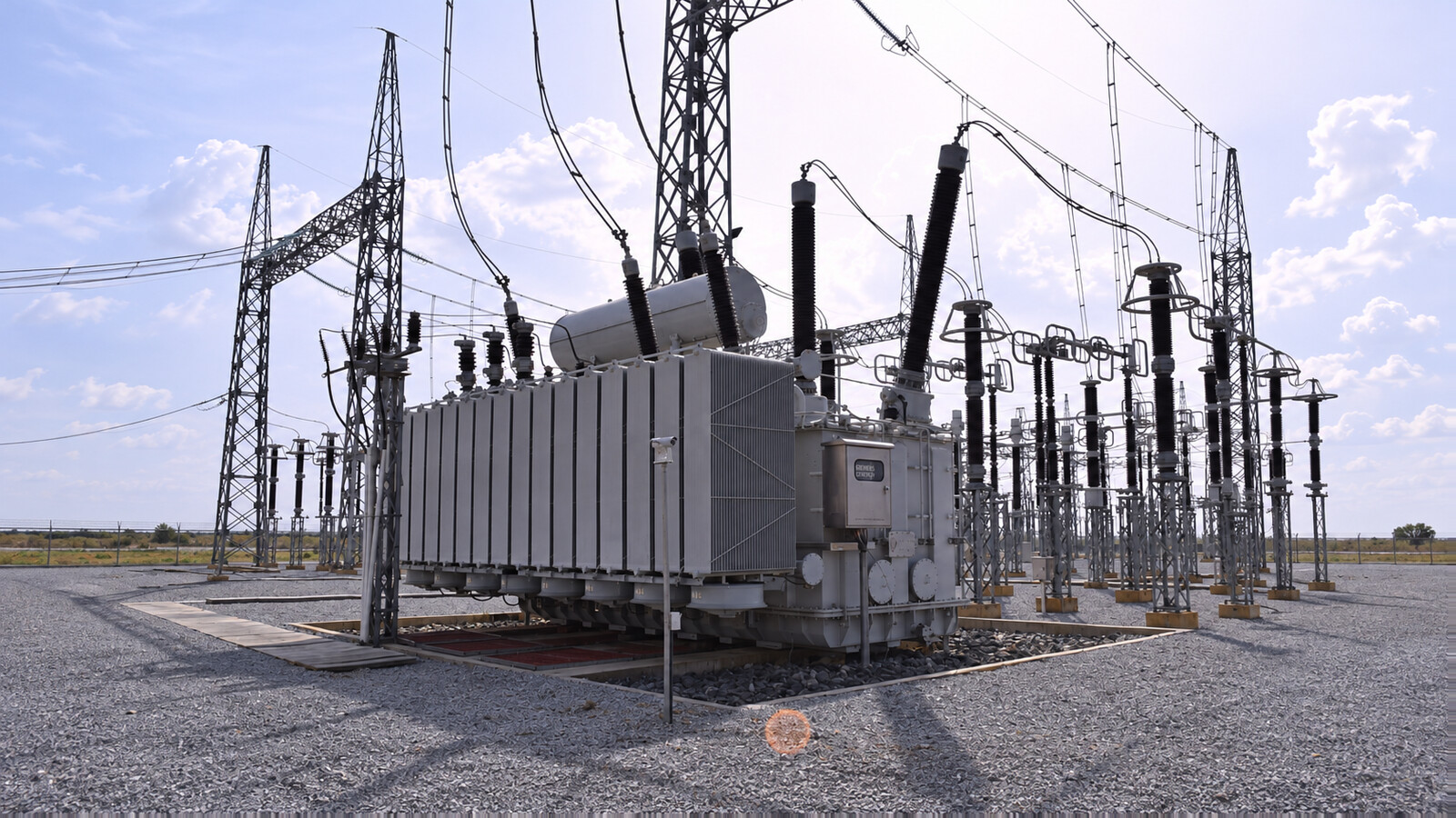
Bushings provide the external winding connections. Radiators or cooler banks transfer heat from the insulating liquid to air. ONAN uses natural oil and air circulation; ONAF adds forced air; OFAF uses forced oil and air; ODAF uses directed oil circulation with forced air. The cooling-stage ratings, fans, pumps and control supply are defined in the accessory and cooling schedule.
Conservator or sealed-tank arrangements, tap-changing equipment, oil valves, temperature indication and protective devices are coordinated with the tank design and installation. A Buchholz relay applies to suitable conservator arrangements and should not be presented as universal equipment on every tank type. Online monitoring, remote communication and additional sensors are options unless included in the purchase specification.
The project requirement is an additional three-phase transformer bay supplying mixed distribution feeders and industrial motor loads. Daily load variation, motor starting and a restricted outage window make voltage regulation, existing-bus interfaces and installation sequencing central to selection.
Selection starts with the feeder demand study, future load allowance and the required operating arrangement. If parallel operation is intended, the existing transformer ratio, vector group, impedance, tap positions and protection settings must be reviewed together. The chosen MVA and cooling stages must meet the continuous and contingency duties without treating the capacity range as a default order rating.
| Project interface | Configuration and acceptance requirement |
|---|---|
| Electrical connection | 110/33kV, three-phase; MVA, vector group, impedance and neutral arrangement defined by the approved system study. |
| Existing substation | Check foundation load, bushing position, busbar clearances, oil containment and crane access against the final general arrangement. |
| Voltage control | Coordinate tap operation and parallel control with the existing transformer and utility voltage policy. |
| Release and energization | Review serial-numbered test reports, approved drawings, alarm/trip functions and receiving records before the agreed site commissioning checks. |
The key engineering issue is compatibility with the operating substation. Approval should resolve busbar alignment and parallel-load-sharing requirements before manufacture; receiving inspection and installation records then provide the link between factory release and site energization.
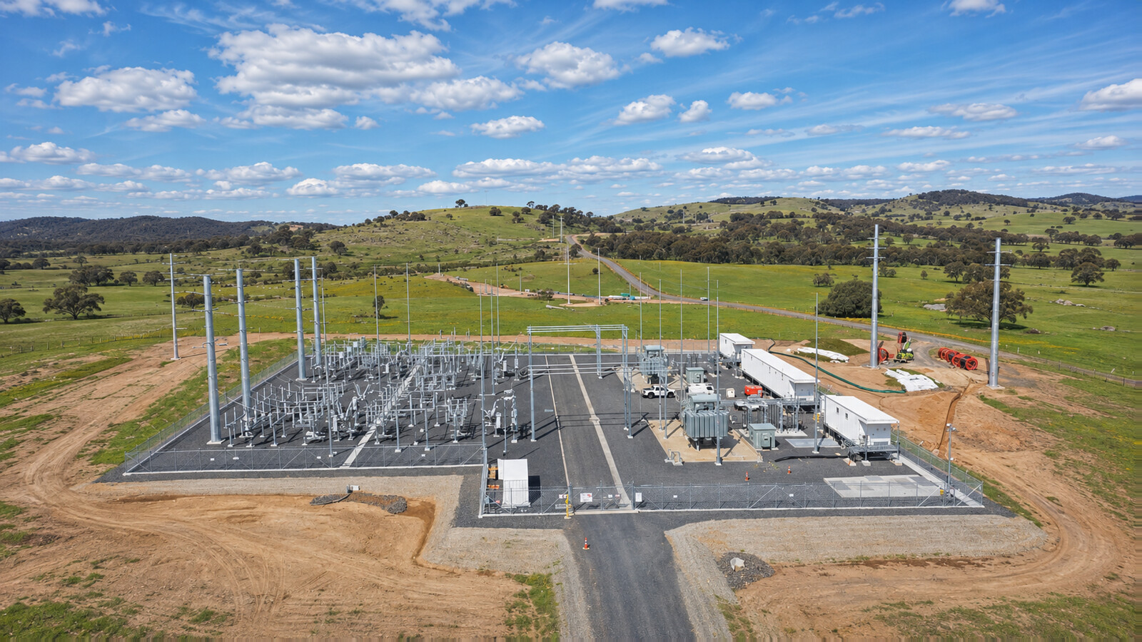
The grid connection links a 34.5kV collector system to a 115kV network. Solar generation, battery charging and discharging, auxiliary demand and reactive-power support create several operating conditions rather than one constant export load.
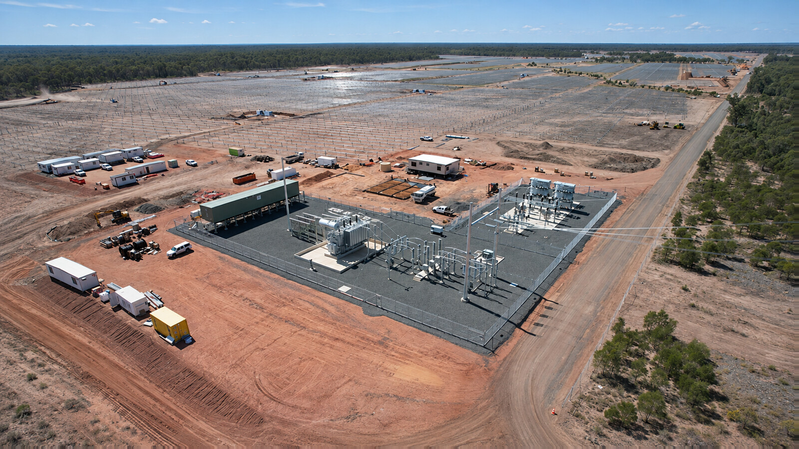
The transformer is selected from the complete three-phase apparent-power envelope. For balanced operation, S = √(P² + Q²), using consistent MW, MVAr and MVA units. Solar and battery nameplate MW values alone do not establish the required transformer MVA; simultaneous operating limits, inverter harmonics, ambient conditions and the utility interconnection study also matter.
| Project interface | Configuration and acceptance requirement |
|---|---|
| Voltage arrangement | 115/34.5kV; confirm winding connection, neutral earthing, highest equipment voltage and insulation coordination. |
| Operating envelope | Evaluate export, charging/import, reactive support and permitted simultaneous operation against the agreed continuous and thermal duty. |
| Control coordination | Coordinate OLTC settings with plant voltage control; define command priority, remote signals and operating limits. |
| Factory evidence | Agree the dielectric schedule, loss and impedance acceptance, cooling-control checks and traceable report package. |
| Site constraints | Confirm access road limits, crane position, detached accessory installation, oil handling and containment before delivery. |
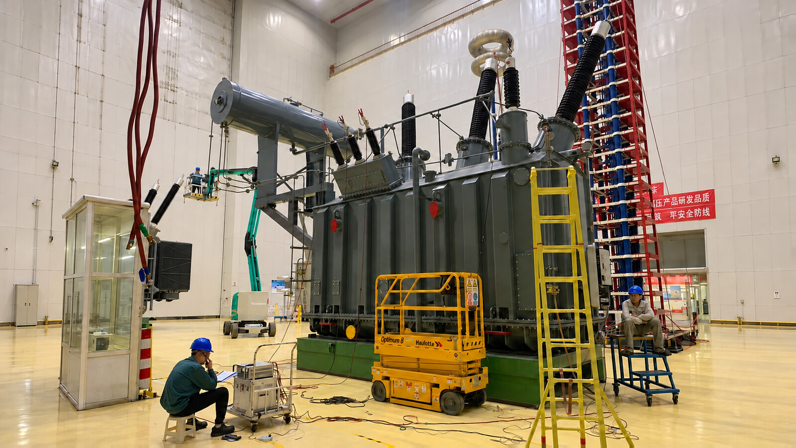
The key engineering issue is coordination between the transformer, inverter plant controller and grid requirements. Acceptance focuses on the approved operating envelope, protection and control interfaces, and the documented transition from factory test release to site checks.
For projects with a different grid voltage, compare the 220kV / 230kV power transformer range. Select the nominal voltage and insulation requirements from the utility specification.
Specifications cover multiple design configurations. Confirm the voltage ratio, winding ratings, insulation levels, cooling stages and accessory scope in the approved technical schedule.
| Parameter | Listed specification / option |
|---|---|
| Product type | Three-phase oil-immersed power transformer |
| Rated voltage / HV options | 110kV / 115kV |
| Rated capacity | 10MVA–240MVA or customized |
| Frequency | 50Hz / 60Hz |
| Medium-voltage options | 6.3kV / 10kV / 10.5kV / 11kV / 13.8kV / 33kV / 34.5kV or customized |
| Low-voltage options | 0.4kV / 0.415kV or customized where applicable; confirm winding duty and rating |
| Cooling options | ONAN / ONAF / OFAF / ODAF |
| Tap changer | OLTC / Off-Circuit Tap Changer |
| Listed tap ranges | Typically ±8×1.25%, ±10×1.25% or customized; ±12×1.25% is a further option requiring confirmation of the tap-changer design |
| Vector group | Dyn11 / YNd11 / YNd1 / customized |
| Winding material | Copper / Aluminum |
| Insulating medium | Mineral transformer oil / ester fluid, subject to the approved design |
| Tank options | Conservator / sealed tank, subject to the approved design |
| Insulation system | Oil-paper |
| Installation | Outdoor / indoor substation, subject to installation requirements |
| Standard framework | IEC 60076 / specified IEEE or ANSI requirements / GB or customized; applicable documents and editions to be agreed |
| Altitude | ≤1000m standard / customized |
| Ambient temperature | Customized according to project requirements |
| Lightning impulse level | According to insulation coordination |
| Impedance | Project-specific |
| Neutral arrangement | Solidly grounded / resistance grounded / customized, as applicable to the winding connection |
Capacity options are 10, 16, 20, 25, 31.5, 40, 50, 63, 80, 100, 120, 150, 180, 200 and 240MVA. Select the rating from the project load study and the agreed cooling duty; voltage class alone does not determine MVA.
Confirm the following design options against the project insulation coordination, fault study and tap-changer requirements before ordering.
| Item | Value requiring project confirmation |
|---|---|
| Lightning impulse insulation level (BIL) | 350–550kV; up to 650kV optional |
| Impedance | 8–12%, with ±7.5% tolerance subject to confirmation of the applicable tolerance |
| Off-circuit tapping | ±8×1.25% or ±2×2.5%; OLTC available |
Further design options include a high-grade grain-oriented steel core, three-limb or five-limb construction, porcelain or composite bushings, project-specific sound and temperature-rise limits, and optional online monitoring. These options require design confirmation and are not all supplied as standard.
110kV and 115kV are separate nominal system voltage options. Confirm the actual network voltage, highest voltage for equipment, insulation coordination and grounding requirements; a tap range alone does not establish interchangeability between the two systems.
| RFQ information | Engineering decision |
|---|---|
| Required MVA and load profile | State continuous demand, overload duration, power factor, expansion allowance and any N−1 duty. |
| Voltage and winding arrangement | Provide HV/MV/LV ratings, two- or three-winding arrangement, tertiary duty and single-line diagram. |
| Fault level and parallel operation | Provide available fault current, clearing time and existing transformer ratio, vector group, impedance and tap data. |
| Cooling and environment | Confirm ambient temperatures, altitude, dust, salt contamination, noise limits, auxiliary supply and cooling redundancy. |
| Voltage regulation | Specify on-load or off-circuit tapping, tap range, control mode, remote signals and coordination with the network or plant controller. |
| Commercial and site interfaces | Provide required standard and edition, delivery destination, access restrictions, foundation limits, cable/busbar interfaces and inspection hold points. |
Voltage combinations include 110/11kV, 110/13.8kV, 110/33kV, 110/10.5kV, 115/13.8kV, 115/11kV, 115/34.5kV and 115/33kV. Three-winding voltage options include 110/33/11kV, 110/33/13.8kV and 115/34.5/13.8kV. The listed 110/10.5/0.4kV and 115/13.8/0.4kV arrangements require confirmation of the purpose and rating of each winding; the low-voltage values are not a universal full-capacity output rating.
Plan shipment using the approved transport drawing, actual shipping mass, dimensions, centre of gravity and route survey. Bridge and axle limits, port handling capacity, overhead clearances, turning space and the final crane position determine the transport method. Main-tank transport may require project cargo or a suitable multi-axle trailer; it should not be described as a complete transformer packed in a standard wooden crate.
Where transport limits require removal of bushings, radiators, the conservator or other accessories, seal and identify each opening and match each detached item to the packing list and installation drawing. Use moisture-resistant protection and suitable crates or pallets for accessories, with supports that protect porcelain, seals and machined surfaces. The approved shipping procedure determines whether the main tank travels with oil or under a controlled dry-gas preservation arrangement, including any monitoring requirements.
Lift and jack only at the points marked on the approved drawing. Select the lifting equipment, spreader arrangement, trailer supports and restraints from the actual load and handling plan; bushings, radiators and pipework are not lifting points. On arrival, check transport records and any fitted impact recorder, preservation pressure where applicable, seals, leaks, external damage and package completeness before unloading or opening the tank. Record discrepancies with photographs and coordinate corrective instructions before installation.
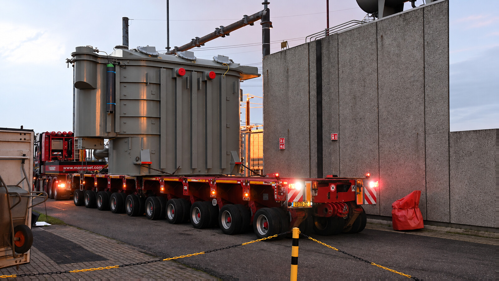
Quality planning starts with the approved drawings, material requirements and inspection and test plan. Manufacturing checks cover material identification, core and winding dimensions, insulation condition, assembly clearances, lead connections, drying records, tank preparation and accessory installation as applicable to the design. These process checks are separate from the completed transformer electrical tests.
The applicable standard, its edition and the purchase contract define the final test schedule, acceptance limits and witness requirements. FAT is the agreed factory acceptance process; it is not a separate product certification and does not mean every possible test is performed on every unit.
| Check or test group | Purpose and agreed scope |
|---|---|
| Visual, mechanical and functional checks | Check identification, dimensions, connections, oil containment, accessory functions, tap operation, cooling controls and alarm/trip circuits against approved documents. |
| Routine electrical tests | Establish winding resistance, voltage ratio and phase displacement, short-circuit impedance and load loss, no-load loss and current, and the applicable dielectric test requirements. Exact procedures, temperature corrections and limits follow the governing standard and approved schedule. |
| Insulation coordination and dielectric tests | Specify applied and induced voltage tests, lightning impulse and partial-discharge measurements as required for the winding voltage class and selected standard. Do not treat these automatically as optional tests or apply one classification to every transformer. |
| Other specified tests | Temperature rise, sound level, zero-sequence impedance, frequency-response analysis, oil tests and other studies or tests are included where required by the applicable standard, design verification plan or contract. Agree the evidence and witness arrangements before order release. |
The acceptance dossier should identify the transformer serial number, approved technical schedule and drawing revisions, instrument calibration references, test methods, measured results and acceptance limits. Record witness attendance, deviations, corrective actions and release approval. Agree whether previous design/type-test evidence is acceptable and which tests must be witnessed on the supplied unit.
For EPC inspection participation and release planning, review the transformer inspection and test plan. Before energization, use the site acceptance and handover checklist with the approved project procedures.
Agree the document register and review dates with the purchase order. Keep the equipment tag, transformer serial number and drawing revision consistent across factory release, packing and site handover records.
| Document package | What the purchaser should confirm |
|---|---|
| Technical schedule and deviations | Winding ratings, voltage ratio, cooling-stage ratings, tapping, impedance, insulation levels and any accepted exceptions. |
| General arrangement and civil interfaces | Operating and transport dimensions, masses, centre of gravity, foundation loads, oil containment, terminal positions and access for maintenance. |
| Protection and control drawings | Auxiliary supplies, terminal numbering, alarm/trip contacts, cooling controls, tap-changer interfaces and any agreed remote communication. |
| Inspection and test plan | Applicable standards and editions, acceptance criteria, witness or hold points, notification periods and the authority for release. |
| Final test dossier | Unit identification, approved methods, calibration references, results, acceptance decisions and closure of recorded deviations. |
| Shipping and installation documents | Packing list, detached accessory identification, lifting and transport drawings, preservation instructions, installation manual and receiving checklist. |
Do not substitute a report for a different transformer for unit-specific routine test evidence. Where earlier design or type-test evidence is proposed, agree its applicability and the acceptance basis with the purchaser before manufacturing release.
Step-down duty between a 110kV or 115kV network and the specified medium-voltage feeders. Review feeder diversity, contingency duty, parallel operation and utility protection interfaces.
Step-up or interconnection duty for generation projects, including renewable plants. Coordinate voltage regulation, reactive-power requirements and the agreed grid connection study.
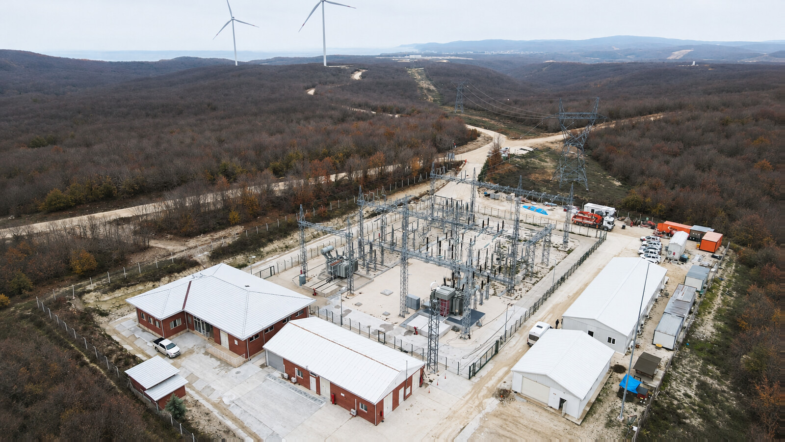
Connection between a medium-voltage collector system and the high-voltage grid. Evaluate charging, export, inverter harmonics and reactive support across the complete permitted operating envelope.
Upstream supply for industrial parks, cement plants, mining, metals and oil-and-gas process facilities. Review motor starting, nonlinear loads, fault level and reliability requirements; a conventional network transformer is not automatically a dedicated furnace or converter transformer.
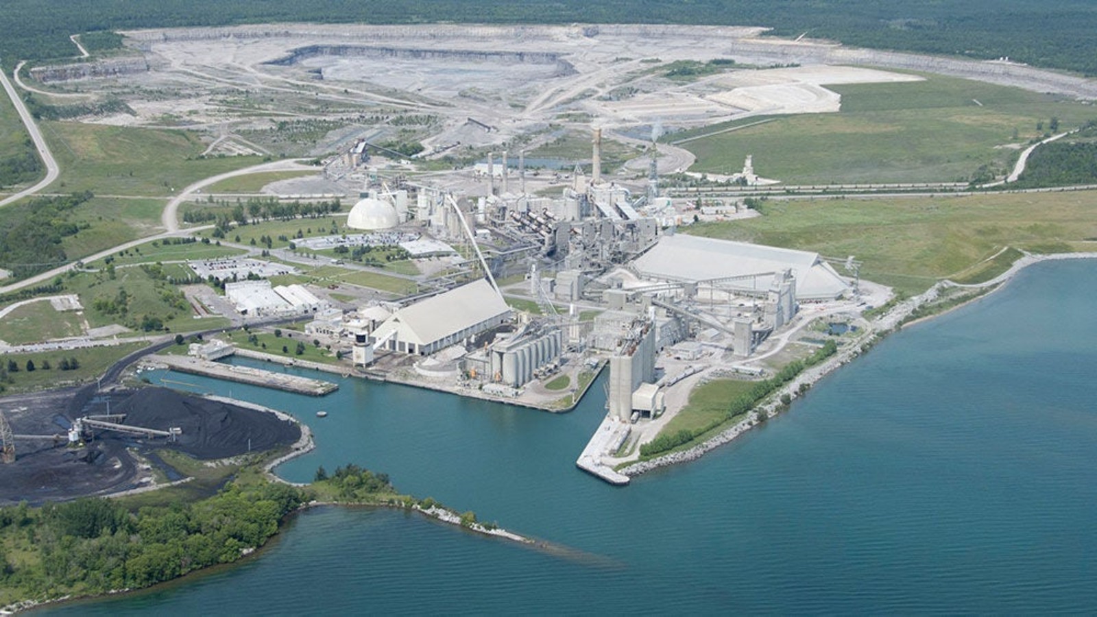
Upstream substation supply for major water systems, transport facilities and other infrastructure. Confirm redundancy, switching arrangements, earthing, site access and the downstream distribution design rather than assuming a direct low-voltage connection.
It connects a 110kV or 115kV high-voltage network to the specified medium-voltage system, or steps generation voltage up for a grid connection. The winding arrangement and MVA rating follow the project single-line diagram and load study.
Not automatically. Check nominal and maximum system voltage, insulation levels, tapping, grounding, clearances and utility requirements. A listed tap range is not sufficient evidence of interchangeability.
The product range is 10MVA–240MVA or customized. Select the actual rating, cooling duty and overload requirements in the approved technical schedule.
Voltage options include 110/11kV, 110/13.8kV, 110/33kV, 110/10.5kV, 115/13.8kV, 115/11kV, 115/34.5kV and 115/33kV. Other listed arrangements require confirmation of each winding rating and duty.
Existing three-winding options include 110/33/11kV, 110/33/13.8kV and 115/34.5/13.8kV. Provide the rating and voltage of every winding, loading combinations, earthing and impedance requirements.
No. The 0.4kV and 0.415kV options apply only where that winding arrangement and duty have been engineered and agreed. They do not define the full-capacity output of the whole range.
ONAN, ONAF, OFAF and ODAF are design options. Natural or forced oil circulation, air cooling, cooling-stage ratings and auxiliary supplies must be specified for the ordered design.
Choose on-load or off-circuit tapping from the voltage regulation study and operating philosophy. Confirm tap range, step size, switching duty, local and remote control, interlocks and maintenance access.
The main specification lists ±8×1.25% and ±10×1.25%, while other existing text also lists ±12×1.25%. A/C additionally list off-circuit ±2×2.5%. Agree one coherent schedule for the ordered transformer.
Review voltage ratio, tap positions, vector group, phase sequence, impedance magnitude and impedance characteristics, rating and the protection scheme of all units. Do not assume matching voltage labels ensure correct load sharing.
Yes, both are design options. The winding material, thermal design, short-circuit withstand requirements and loss guarantees must be agreed for the actual transformer.
Mineral transformer oil and ester fluid are design options. Fluid choice affects the insulation, cooling, fire assessment, seals and handling procedure and requires design confirmation.
No. A fluid choice or reference to a technical standard is not a certification. Request the actual certificates, test reports and their model and scope where certification is a purchase requirement.
Agree the applicable IEC 60076 parts, specified IEEE/ANSI documents or GB requirements and editions in the contract. These are technical requirements, not interchangeable certificates.
FAT follows the agreed inspection and test plan. It combines document review, agreed checks and witnessed tests; exact scope, limits and release points must be defined before manufacture.
Their requirements and classification depend on the winding voltage class, applicable standard and contract. Define the dielectric test schedule explicitly rather than describing all such tests as optional or universal type tests.
Reports should identify the serial number, rating, test date, approved drawing revisions, method, calibrated equipment references, measured results and acceptance limits. Deviations and release decisions should remain traceable.
Provide actual altitude, ambient temperatures, salt or dust conditions, wind and seismic requirements. External insulation, cooling, corrosion protection and clearances require review for the site.
The accessory schedule may include gas-actuated protection where applicable, pressure relief, oil and winding temperature indication, oil level indication, cooling alarms and tap-changer protection. Online monitoring is optional unless expressly included.
Provide inverter data, harmonics, reactive power requirements, simultaneous export/import cases, auxiliary demand and grid-code requirements. Size in MVA using the complete operating envelope rather than adding installed MW ratings.
Use the actual transport mass and dimensions, route survey and approved lifting and restraint plans. Main-tank transport and separately protected accessories are selected for the unit; standard container or wooden-crate shipment is not assumed.
Check package identification and completeness, seals, external damage, leaks, preservation condition and any fitted transport recorder before unloading or opening. Record discrepancies and follow the approved receiving procedure.
Send the single-line diagram, MVA, voltage ratios, frequency, vector group and earthing, impedance, tapping, cooling, insulation levels, site conditions, applicable standards, required documents, FAT requirements and delivery destination.
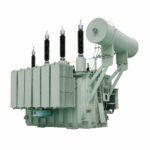 110kV 115kV Power Transformer
