 zishengelectric




Project Partners
Phone/WhatsApp: 8619131285373
Email: info@zishengtransformer.com
Factory Headquarters: No. 118, Jingyi Street, Economic Development Zone.
Search productSearch post
Project Partners
Phone/WhatsApp: 8619131285373
Email: info@zishengtransformer.com
Factory Headquarters: No. 118, Jingyi Street, Economic Development Zone.
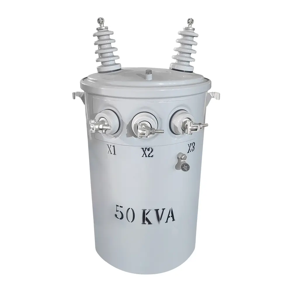
The 50kVA conventional single-phase pole-mounted transformer is designed to step medium-voltage distribution power down to a stable low-voltage supply. It is commonly installed on utility poles for residential communities, rural electrification, farms, small commercial facilities and municipal distribution networks.
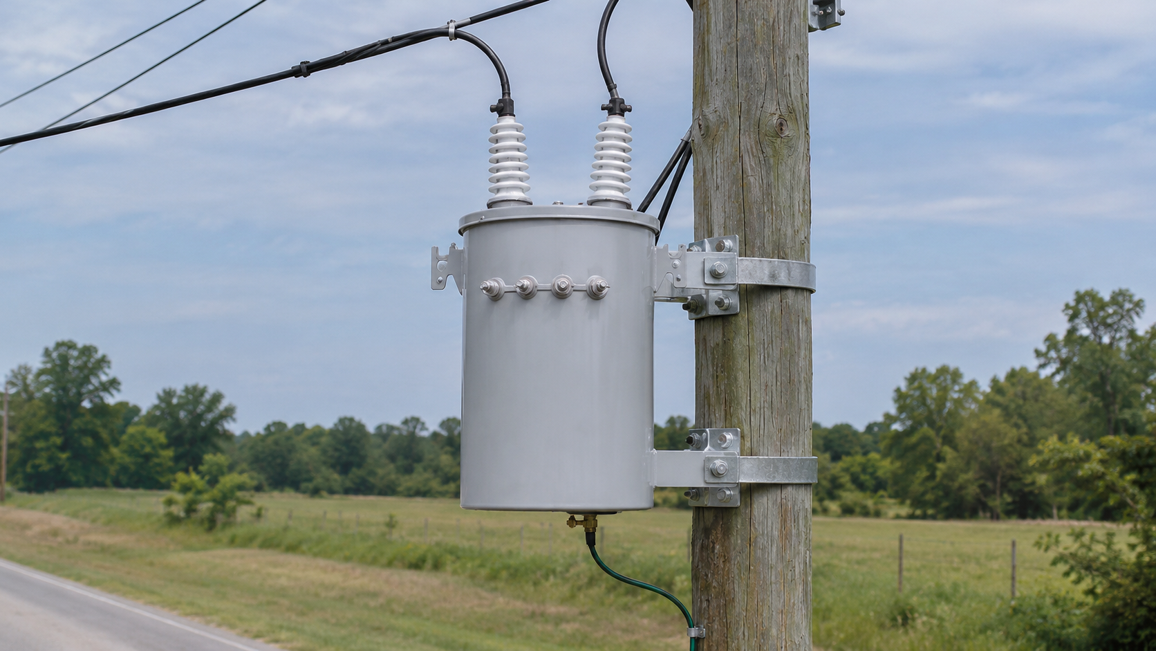
Unlike a CSP transformer, the conventional type normally relies on externally installed primary fuses, surge arresters and secondary protection. Primary voltage, secondary voltage, winding material, insulating fluid, bushings and mounting accessories can be customized for different utility standards.
| Parameter | Standard Configuration / Options |
|---|---|
| Rated Capacity | 50kVA |
| Transformer Type | Conventional single-phase pole-mounted transformer |
| Phase | Single phase |
| Primary Voltage | 2.4kV–34.5kV or customized |
| Secondary Voltage | 120/240V, 240/480V, 277V or customized |
| Rated Frequency | 50Hz or 60Hz |
| Cooling Method | ONAN |
| Winding Material | Copper or aluminum |
| Core Material | Cold-rolled grain-oriented silicon steel |
| Insulating Fluid | Mineral oil or natural ester fluid |
| Tapping Range | Typically ±2 × 2.5% or customized |
| Temperature Rise | 55°C, 65°C or project-specific |
| Tank Construction | Sealed cylindrical steel tank |
| Primary Bushing | One- or two-bushing configuration |
| Secondary Bushings | Three- or four-bushing arrangement |
| Mounting | Single-pole mounting brackets |
| Installation | Outdoor |
| Standard Altitude | Up to 1,000m; high-altitude design available |
| Ambient Temperature | According to IEEE, CSA, IEC or project requirements |
| Applicable Standards | IEEE C57, ANSI, CSA, IEC 60076 or specified utility standard |
| Polarity | Additive or subtractive according to the approved design |
| Finish | Weather-resistant coating; custom colour available |
| Expected Service Life | Approximately 25–30 years with correct loading and maintenance |
Common primary and secondary voltage combinations include:
The primary voltage should be specified as both the system voltage and the actual phase-to-neutral voltage applied to the transformer.
| Voltage Side | Example Voltage | Approximate Rated Current |
|---|---|---|
| Primary | 7.2kV | 6.94A |
| Primary | 13.2kV | 3.79A |
| Primary | 14.4kV | 3.47A |
| Primary | 24.94kV | 2.00A |
| Secondary | 240V | 208.3A |
| Secondary | 480V | 104.2A |
Rated current values are calculated from the full 50kVA capacity and must be confirmed against the approved voltage configuration.
The cylindrical tank and integrated mounting brackets provide a compact installation footprint. The transformer is suitable for overhead distribution systems where ground space is limited.
The core uses grain-oriented electrical steel with optimized joints to reduce no-load loss, excitation current, operating noise and vibration.
Copper or aluminum conductors can be supplied. The winding structure is mechanically reinforced to withstand short-circuit forces, voltage fluctuations and normal transportation stresses.
The core and coil assembly is immersed in insulating fluid, which provides electrical insulation and transfers heat to the tank wall. ONAN cooling requires no external fans or pumps.
The sealed tank limits contact between the insulating fluid and outside air, helping reduce moisture ingress, oxidation and maintenance requirements.
The transformer can be supplied with:
| Feature | Conventional Type | CSP Type |
|---|---|---|
| Primary Fuse | Normally installed externally | Usually integrated |
| Surge Arrester | Normally installed externally | May be factory-mounted |
| Secondary Breaker | Not normally included | Commonly integrated |
| Protection Coordination | Designed by utility or project engineer | Partially integrated into transformer |
| Maintenance | Simple transformer construction | More integrated components |
| Application | Flexible utility protection schemes | Standardized distribution networks |
A typical 50kVA conventional pole-mounted transformer includes:
Available accessories include:
| Customizable Item | Available Options |
|---|---|
| Primary Voltage | 2.4kV–34.5kV |
| Secondary Voltage | 120/240V, 240/480V, 277V or customized |
| Frequency | 50Hz or 60Hz |
| Winding Material | Copper or aluminum |
| Primary Connection | Single-bushing or dual-bushing |
| Secondary Connection | Centre-tapped or project-specific |
| Tap Range | Standard or customized off-circuit taps |
| Insulating Fluid | Mineral oil or natural ester |
| Temperature Rise | 55°C or 65°C |
| Efficiency | Utility- or market-specific efficiency level |
| BIL | Selected according to the voltage class |
| Tank Material | Carbon steel or stainless steel |
| Paint Colour | Light grey, green or custom colour |
| Corrosion Protection | Standard, coastal or heavy-duty system |
| Mounting | Standard or customized pole brackets |
| Accessories | Arresters, fuse brackets, wildlife guards and terminal covers |
| Standards | IEEE/ANSI, CSA, IEC or customer specification |
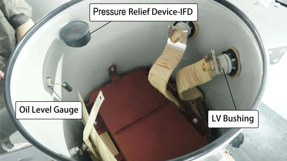
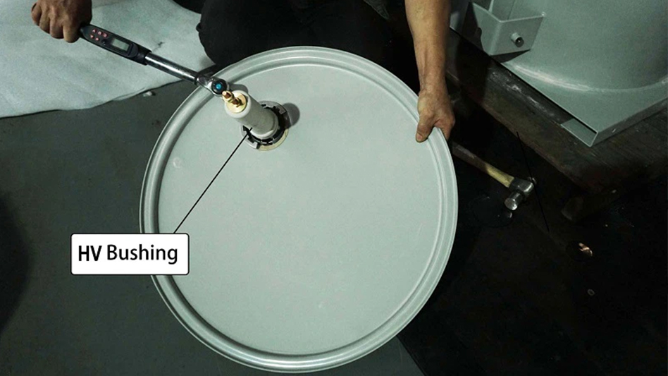
The oil-immersed assembly comprises a magnetic core, insulated windings, internal leads, a cylindrical tank, high- and low-voltage bushings, mounting brackets, lifting provisions and an identification nameplate. Confirm the winding conductor, core material, insulating fluid, tank finish and accessory schedule in the approved technical offer.
In an ONAN configuration, the insulating liquid circulates naturally and transfers heat through the tank to the surrounding air. The cooling designation, permissible temperature rise and site conditions must match the selected design. Bushings and terminals provide electrical connections; they are not lifting or cargo-restraint points.
Check primary and secondary terminal arrangements, clearances, grounding connections and bracket dimensions against the utility drawing. Pressure-relief devices, tap changers and other accessories are supplied only as identified in the agreed scope.
For a 50 kVA conventional single-phase pole-mounted transformer, begin with the utility connection and the simultaneous load schedule. The 50 kVA rating describes apparent power; it does not by itself establish motor-starting capability or the number of customers that can be supplied.
A single-bushing primary requires a compatible grounded system and an approved return path. A two-bushing arrangement must also match the utility connection. Off-circuit taps must only be operated with the transformer isolated and de-energized.
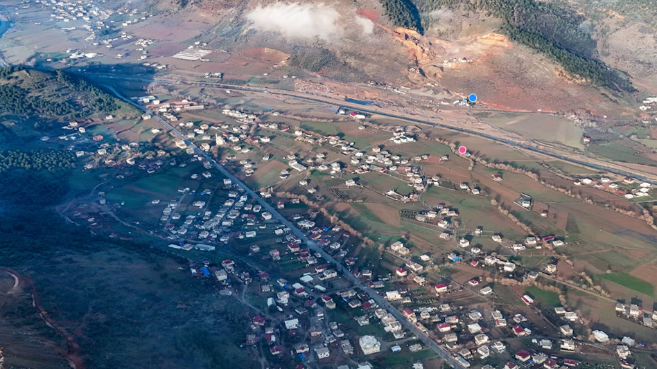
The supply requirement combines household lighting, refrigeration, small appliances and community facilities connected to an overhead distribution line. Demand diversity, evening peaks and the distance to the furthest service point are the main selection considerations. The 50 kVA unit is assessed against the simultaneous apparent load and the utility's permitted voltage drop.
| Engineering item | Case requirement |
|---|---|
| Transformer | 50 kVA conventional single-phase pole-mounted design |
| Connection | Utility-approved primary voltage, secondary service arrangement, frequency and grounding |
| Load assessment | Coincident household and community demand, power factor and growth allowance |
| Site limits | Pole loading, bracket compatibility, public clearances and secondary feeder length |
| Protection | Coordinated external primary protection, surge protection and downstream devices |
| Acceptance documents | Approved drawing, connection diagram, nameplate, traceable routine test report and packing list |
Where a center-tapped secondary is ordered, the service design distributes loads between the two legs and checks neutral loading. Pole strength and mounting details require approval before installation; a compact tank does not establish the suitability of an existing pole. Acceptance checks verify ratio, polarity, terminal identification and the approved protection interfaces.
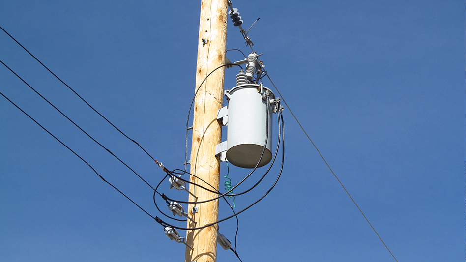
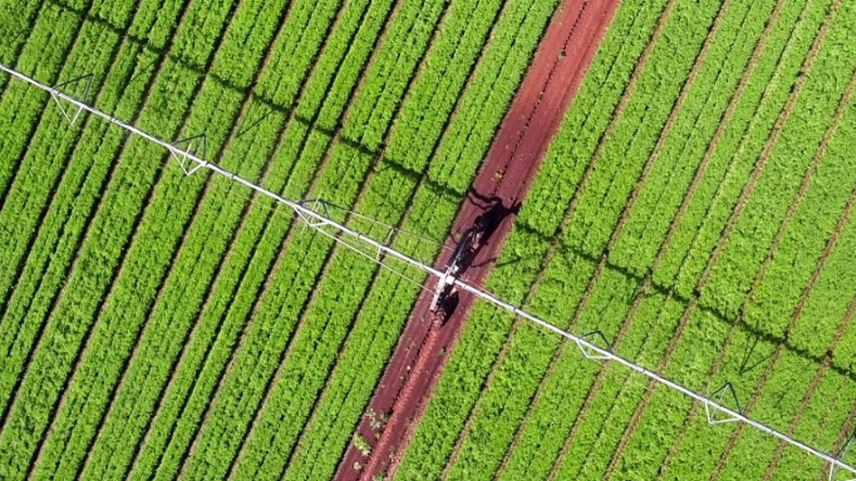
The farm supply combines compatible single-phase water pumping, ventilation, lighting and control equipment. Irrigation and ventilation can operate together during warm periods, while long cable runs increase the risk of starting voltage drop. The load schedule therefore records electrical input current, power factor, operating overlap and the largest motor's starting method.
| Engineering item | Case requirement |
|---|---|
| Transformer | 50 kVA conventional single-phase pole-mounted design |
| Connected equipment | Single-phase motors and auxiliary loads compatible with the approved secondary voltage |
| Selection basis | Simultaneous kVA, motor starting current, permitted voltage dip and future demand |
| Pole location | Utility access, structural capacity, maintenance clearance and a practical secondary cable route |
| Configuration | Confirmed ratio, frequency, tapping arrangement, fluid, mounting and external protection scope |
| Acceptance | Approved load and connection schedules, routine test records, accessory check and arrival inspection |
The motor review separates mechanical output from electrical input and checks whether another motor can start while the irrigation pump is running. Three-phase pumps cannot connect directly to this single-phase secondary. The final cable and protection design must address starting duty, short-circuit conditions and selective operation, rather than relying only on the transformer's 50 kVA rating.
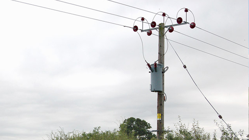
Compare the 75 kVA conventional pole-mounted transformer where the assessed demand requires a larger rating, or browse the pole-mounted transformer range. For the inquiry checklist, read our distribution transformer selection guide.
| Customizable Item | Available Options |
|---|---|
| Rated Capacity | 50kVA or customized according to load requirements |
| Primary Voltage | 2.4kV–34.5kV |
| Secondary Voltage | 120/240V, 240/480V, 277V or customized |
| Frequency | 50Hz or 60Hz |
| Winding Material | Copper or aluminum |
| Primary Connection | Single-bushing or dual-bushing configuration |
| Secondary Connection | Centre-tapped or project-specific arrangement |
| Polarity | Additive or subtractive |
| Tap Changer | Off-circuit tap changer |
| Tapping Range | ±2 × 2.5% or customized |
| Impedance | Customized according to utility and protection requirements |
| Insulation Level | BIL selected according to the primary voltage class |
| Insulating Fluid | Mineral oil or natural ester fluid |
| Temperature Rise | 55°C, 65°C or project-specific |
| Efficiency Level | Customized to utility or local regulatory requirements |
| Tank Material | Carbon steel or stainless steel |
| Tank Colour | ANSI 70 grey, green or specified RAL colour |
| Corrosion Protection | Standard, coastal or heavy-duty coating system |
| Mounting Arrangement | Standard or customized pole-mounting brackets |
| Primary Terminals | Eyebolt, clamp or customer-specified connector |
| Secondary Terminals | Stud, spade, eyebolt or customized connector |
| External Protection | Fuse cutout and surge arrester mounting provisions |
| Pressure Protection | Automatic pressure-relief device |
| Wildlife Protection | Bushing covers, bird guards and insulated terminal covers |
| Oil Accessories | Oil-level plug, drain valve and sampling valve |
| Grounding | Tank-grounding pads, straps or customized connectors |
| Dual-Voltage Design | Series-multiple or dual-voltage switch available |
| Nameplate and Labels | English, bilingual or customer-specified language |
| Applicable Standard | IEEE/ANSI, CSA, IEC or customer utility standard |
| Documentation | Drawings, data sheets, test reports and installation manuals |
| Inspection | Customer-witnessed FAT or third-party inspection |
| Packaging | Pallet, wooden case or seaworthy export packaging |
All options are finalized according to the distribution-system voltage, utility specifications, environmental conditions and approved transformer drawings.
For a 50 kVA conventional single-phase pole-mounted transformer, begin with the utility connection and the simultaneous load schedule. The 50 kVA rating describes apparent power; it does not by itself establish motor-starting capability or the number of customers that can be supplied.
A single-bushing primary requires a compatible grounded system and an approved return path. A two-bushing arrangement must also match the utility connection. Off-circuit taps must only be operated with the transformer isolated and de-energized.
For this pole-mounted unit, specify upright transport on a secured pallet, protective wooden frame or crate according to the route and handling conditions. Confirm the packed dimensions, gross weight and lifting method from the final packing documents; equipment weight alone is not the shipping weight.
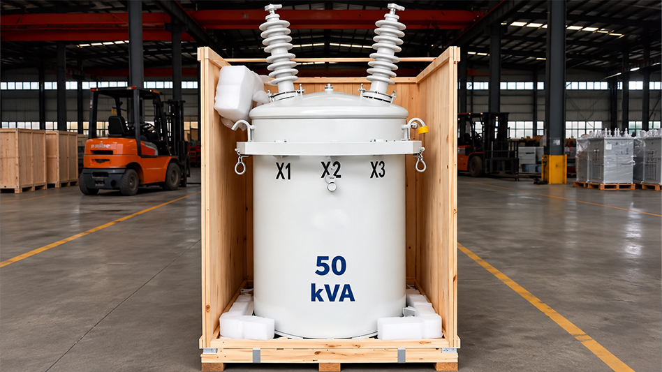
Restrain the tank through approved structural points and keep frame members clear of bushings, terminals, valves and handles. Protect exposed connections and coating, identify separately packed accessories and apply moisture protection suitable for storage and transit. Wood packaging must meet the destination's applicable phytosanitary requirements.
Use rated lifting equipment and the designated lifting lugs. Forklifts handle a suitable pallet or base rather than pressing against the tank or bushings. Keep the unit upright and secure it against movement during transport. Pole installation must follow the approved drawing and the utility's electrical and structural requirements.
Agree the packing list, commercial invoice, transport document, approved drawings, nameplate data, factory test reports and installation instructions before dispatch. On arrival, check package condition, serial number, accessory quantities, tank coating, bushings, terminals and signs of oil leakage. Record damage with photographs and notify the carrier and supplier promptly. Do not energize equipment with unresolved damage or leakage.
Manufacturing inspection for the 50 kVA conventional single-phase pole-mounted transformer covers materials, assembly and final configuration against the approved design. The inspection plan defines the checks and records required for the order.
Check the specified core and winding materials, insulating components, fluid documentation, bushings and tank components for identification, condition and conformity to purchasing requirements. Retain material or component records where required by the contract.
Inspect winding assembly, insulation placement, internal connections, terminal marking, tank cleanliness, seals and the mounting arrangement. Confirm the fluid filling and drying procedures applicable to the selected design. Final assembly checks compare the nameplate and accessories with the approved drawing.
Confirm completion of the agreed routine tests, final appearance and leak checks, traceable reports and packing inspection. Where witnessed FAT is specified, agree hold points and notification requirements before manufacture. Additional type or special tests follow the governing standard and purchase contract.
Agree the applicable standard, inspection and test plan, acceptance limits and document list before manufacture. Visual and dimensional checks cover the tank, coating, bushings, mounting points, terminals, accessories and nameplate against the approved drawing.
| Inspection or test | Purpose and record |
|---|---|
| Winding resistance | Check winding and connection consistency; record measurement temperature and tap position. |
| Voltage ratio and polarity | Verify the specified ratio, terminal identification and polarity. |
| No-load loss and excitation current | Assess the magnetic circuit under the specified voltage and frequency. |
| Load loss and impedance | Verify loss and impedance values using the conditions and corrections required by the governing standard. |
| Dielectric tests | Assess insulation withstand using the procedures and test levels applicable to the ordered design. |
| Tank tightness and final inspection | Check seals, fittings, oil leakage, identification and completeness using the agreed procedure. |
The governing standard and contract determine the routine test scope. Lightning impulse, temperature-rise, sound-level and other type or special tests must be identified separately where required; their test category and frequency depend on the selected standard. Insulating-fluid tests and additional checks are included as specified in the inspection plan.
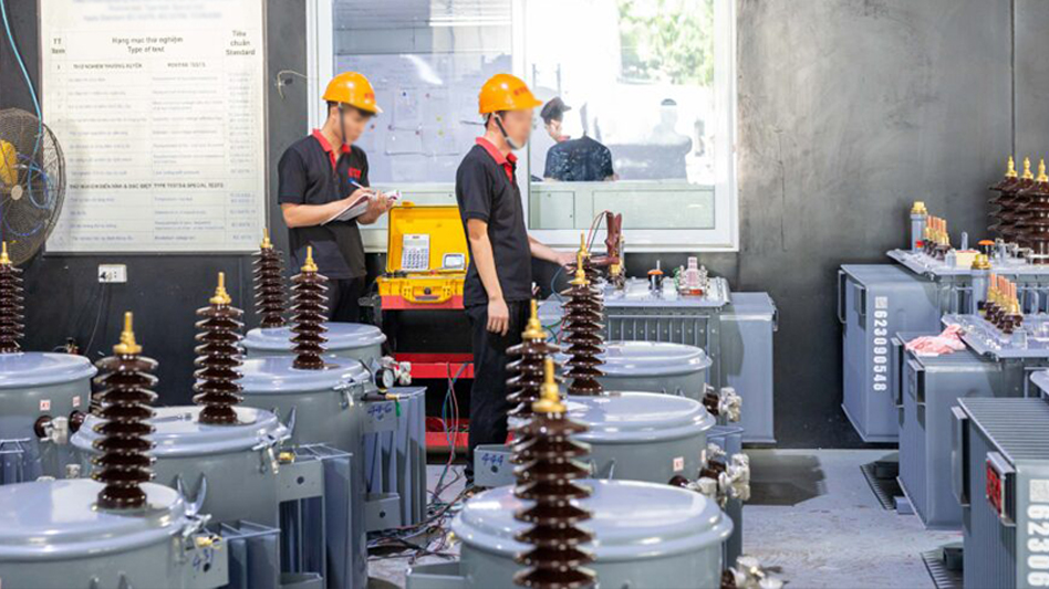
Match the transformer serial number to its nameplate, approved datasheet and test report. Reports should identify test procedures, conditions, measured values and acceptance criteria. Agree witness or hold points, notice periods and any independent inspection before production. Shipment release should follow closure of outstanding inspection items.
Supply villages, scattered homes, schools and community facilities where the utility-approved single-phase service and assessed demand match the transformer. Review future load growth and the length of secondary circuits.
Serve residential service groups on an overhead network. Confirm the secondary wire arrangement, grounding, customer diversity and voltage-drop limits. Balance loads across the two legs when a center-tapped secondary is specified.
Supply compatible single-phase irrigation equipment, farm buildings, lighting and control systems. Review motor input current, starting duty and the distance to the pump. Three-phase motors require a compatible three-phase supply arrangement.
Support shops, offices and small workshops with suitable single-phase loads. Include refrigeration, air-conditioning starting current and operating schedules in the demand assessment.
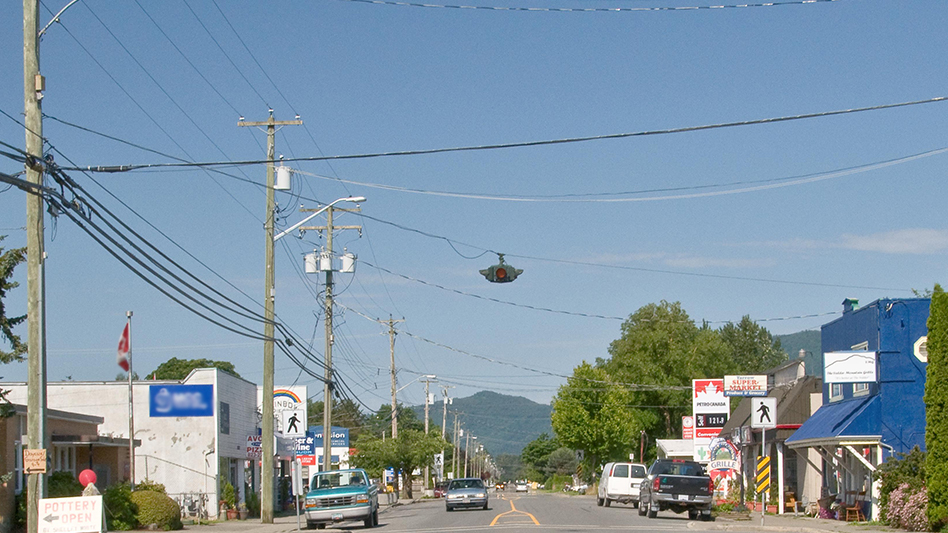
Use for approved overhead service points and replacements where mounting dimensions, insulation coordination, terminal arrangements and external protection match the utility design.
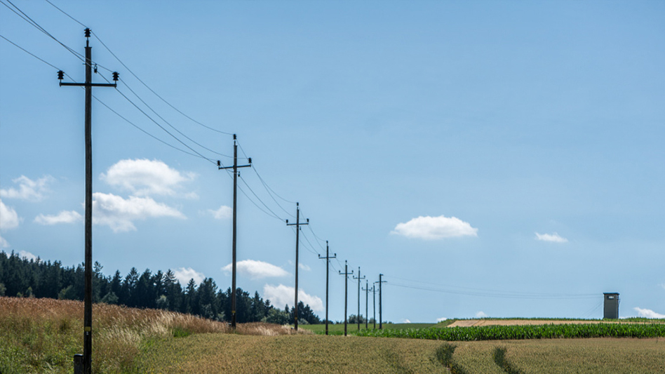
It is a single-phase oil-immersed transformer installed on a utility pole to convert medium-voltage electricity into low voltage for residential, agricultural and small commercial loads.
A conventional transformer normally uses externally installed fuse cutouts, surge arresters and secondary protection. A CSP transformer usually integrates some of these protective devices into the transformer.
Primary voltages from 2.4kV to 34.5kV are available. Common ratings include 7.2kV, 7.62kV, 7.97kV, 12.47kV, 13.2kV, 13.8kV, 14.4kV and 24.94kV.
Common secondary voltages include:
At the full 240V winding, the approximate rated current is 208.3A. For a centre-tapped system, load balancing between the two 120V sections must be considered.
Yes. Both copper and aluminum windings are available. Selection depends on the utility specification, efficiency requirement, transformer weight and project budget.
Yes. The transformer can be designed for either 50Hz or 60Hz. The required frequency must be confirmed before production.
The standard cooling method is ONAN—Oil Natural Air Natural. It uses natural oil circulation and surrounding air without fans or pumps.
Standard mineral transformer oil and natural ester fluid are available. Natural ester fluid may be selected for improved fire safety and environmental performance.
Yes. Both single-bushing and dual-bushing primary configurations can be supplied according to the utility grounding system.
The conventional type normally does not include integrated protection. External fuse cutouts and surge arresters can be supplied separately or with mounting provisions.
Yes. An off-circuit tap changer with a typical range of ±2 × 2.5% can be provided. Other tapping ranges are available when specified.
Yes. Coastal configurations can include enhanced paint systems, stainless-steel hardware, improved sealing and corrosion-resistant terminals.
Yes. High-altitude designs are available. Insulation clearances and thermal performance must be adjusted according to the installation altitude.
The transformer can be manufactured according to IEEE C57, ANSI, CSA, IEC 60076 or a customer-specified utility standard.
The applicable standard and purchase specification define the routine test scope. The agreed inspection plan identifies winding resistance, ratio and polarity, loss and impedance measurements, dielectric procedures, tank tightness and any additional checks required for this design. Type or special tests and customer witness points are agreed separately.
Yes. Customer-witnessed FAT or independent third-party inspection can be arranged before shipment.
The transformer is secured vertically on a reinforced pallet with protected bushings, sealed terminals and moisture-resistant wrapping. A wooden export case is available when required.
Routine maintenance normally includes checking the tank for leakage, inspecting bushings and terminals, verifying grounding, examining external protection devices and monitoring the transformer’s loading condition.
Please provide:
Service life depends on the approved design, loading, environment, installation and maintenance. Confirm the design-life requirement and warranty terms in the technical offer. Routine maintenance includes leakage and bushing inspection, grounding and external protection checks, and review of loading conditions.
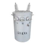 50kVA Conventional Type Single Phase Pole Mounted Transformer
