 zishengelectric



news
News Center
Providing high-quality power to the world
Search productSearch post
news
Providing high-quality power to the world
Zisheng Electric works with EPC teams that must hand over transformers, switchgear and control rooms as usable systems, not isolated items of equipment. A substation water ingress walkdown is a practical gate before acceptance: it follows the paths water could take from the roof, yard and cable entries to a live electrical compartment. The inspection must link building fabric, civil drainage, equipment enclosures, HVAC and document ownership. A dry floor on a sunny day is weak evidence. The team needs to know what happened during rain, where water would collect, how it would be detected, and who is responsible for repairing a defect before the operating team accepts the site.
This guide is for EPC construction managers, commissioning engineers, owners and electrical equipment purchasers. It focuses on decisions that can be made at the handover boundary. It does not assign a universal weatherproofing rating or substitute for the project’s civil design. The approved drawings, equipment manuals, local conditions and contractual acceptance criteria govern each site.
Mark the inspection area on a current layout, roof plan, drainage drawing and single-line diagram. Include the control building, transformer marshalling cabinets, cable trenches, outdoor kiosks, prefabricated enclosures and adjacent yard levels. Identify the upstream roof and paved areas that drain toward these assets, even if they sit outside the electrical subcontractor’s package. A roof outlet blocked upstream can flood a room whose door seals appear sound. Conversely, water found inside a cabinet may originate in an unsealed cable route rather than its door.
Record equipment tags, building zones, inspection date, recent weather, temporary covers and the construction status. Separate permanent installed condition from temporary protections used during construction. A tarpaulin, temporary pump or taped penetration must not silently become the accepted operating arrangement. The boundary should also show which equipment is energized, isolated or awaiting testing so that inspection access follows site safety rules.
Start outside and work inward. Trace rain from roof falls to outlets, downpipes, paved grades and drains. Then examine openings: roof penetrations, wall joints, cable and conduit entries, louvers, doors, windows and equipment glands. Finally look at the consequences inside: standing water, staining, corrosion, wet insulation, failed heaters, blocked cable trenches or compromised access. This sequence prevents a team from treating a visible puddle while leaving the actual path open.
The table turns a general visual walkdown into a release decision. Values and tests must come from the project specification and supplier instructions; the examples below are categories of evidence, not generic pass limits.
| Interface | Why it matters | Evidence to request | Decision if unresolved |
|---|---|---|---|
| Roof, outlets and downpipes | Overflow can reach electrical rooms through joints or ceiling penetrations. | As-built falls, outlet clearance, waterproofing closeout and observed drainage after rain. | Trace and repair the source; protect affected equipment and repeat observation. |
| Doors, thresholds and louvers | Wind-driven rain or yard runoff can enter a room or enclosure. | Installed seals, threshold levels, door closure, louver drainage and adjacent yard grades. | Hold acceptance of exposed spaces until the route is corrected. |
| Cable and conduit entries | An opening can conduct water into trenches, panels or transformer auxiliaries. | Penetration schedule, approved sealing system, photographs before concealment and final inspection. | Open an item for the responsible trade and verify the completed seal. |
| Trenches, sumps and site drains | Water can accumulate below cables and re-enter through connected ducts. | Drain route, sump controls, discharge ownership, cleaning and functional checks. | Define temporary control only through authorized project risk review. |
| Cabinets and electrical equipment | Moisture may affect insulation, terminals, controls and warranty evidence. | Equipment-specific inspection, heater operation, gland condition and supplier disposition. | Do not energize affected equipment until the responsible engineer releases it. |
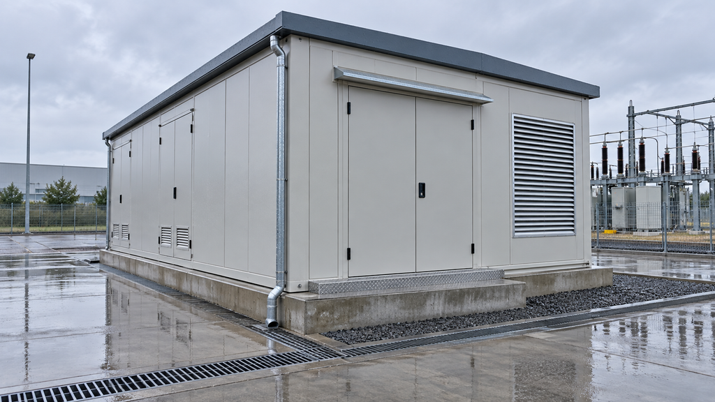
A roof can look complete from the yard while a small curb, flashing or maintenance opening remains unfinished. Compare the installed roof with the approved roof plan and the manufacturer’s detailing instructions. Check outlet access, overflow route, parapet junctions, rooftop equipment supports and penetrations made after the waterproofing contractor’s work. The roof contractor should identify how later work was reinstated and inspected. Photographs are useful when they show the exact location and drawing reference; a wide photograph without a tag rarely proves closure.
At walls, examine panel joints, window perimeters, door frames, pipe sleeves and cable entries. Record cracks or incomplete sealant and ask whether movement joints are being treated as movement joints. A rigid patch across a moving joint may look neat at handover and fail in service. The civil designer and approved system supplier should resolve the detail, while the EPC team tracks the electrical equipment exposed below it.
Door seals alone cannot solve a yard that slopes toward the control room. Review as-built levels and observe the direction of surface runoff after rain or an agreed water test. Confirm that grates and channels can be cleaned and that their discharge does not return water to another equipment area. Do not obstruct a drain with temporary storage or cable reels during the final inspection. Where the building has a raised threshold, check the interface with access ramps and equipment movement; an improvised ramp can bridge the threshold and redirect water indoors.
Trenches and duct banks require their own route review. A dry room may connect to a flooded trench through a low duct. Verify the intended slope, seals, drain or sump arrangement, and the operating team’s access for maintenance. For a prefabricated substation, treat the roof, enclosure base, ventilation openings and cable-entry floor as one package. The prefabricated substation product configuration must be matched to its actual foundation and site drainage, not judged by a catalogue photograph.
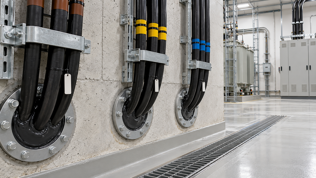
A penetration seal may have to serve water control, fire separation, mechanical support and later cable replacement. Confirm the approved system for each opening and record cable count, spare capacity, sleeve geometry and installer instructions. Do not fill an opening with an unapproved compound merely because it stops visible water. The fire boundary and maintainability may be compromised. The related transformer cable termination interface guide explains why electrical clearance, screen bonding and sealing records need to remain coordinated.
For concealed penetrations, obtain pre-close photographs and a marked-up schedule. At the final walkdown, verify exposed faces, gland tightening to the selected system’s instructions, unused openings, cable support and any drain path inside the enclosure. The electrical and civil teams should sign a common closure record rather than each assuming the other has accepted the sleeve.
Water inside a control building may arise from condensation, HVAC condensate, a plumbing leak or rainwater. Diagnosis matters because the remedy differs. Record the location, time, temperature and recent operating state. Inspect condensate trays and discharge lines, ventilation openings, door use during construction and space-heater supplies. A dehumidifier can reduce immediate exposure while the source is investigated, but it is not proof that the envelope is complete.
If moisture has reached a switchgear compartment or transformer marshalling cabinet, preserve the condition and seek the equipment supplier’s inspection and test advice before energization. Do not clean or dry an affected enclosure and then declare it sound solely from its appearance. The transformer site acceptance test checklist provides a useful framework for tying installation observations to tests and release records. The specific inspection and retest scope must reflect the actual exposure.
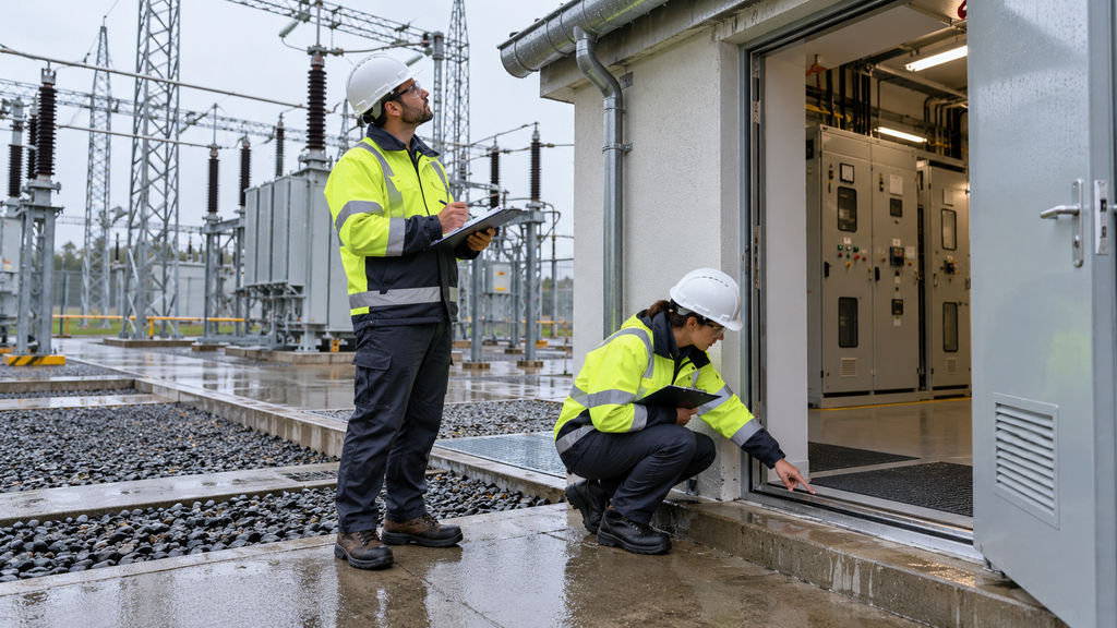
A controlled water test may help locate a leak, but it must be planned around electrical isolation, drainage capacity, finishes and supplier limits. Agree the method and acceptance criterion before testing. Record the starting condition, application area, duration, personnel and observations at the receiving side. Never spray energized electrical equipment to prove enclosure performance. A test that wets hidden insulation can create a new defect. Rain observation is often valuable, provided the team documents rainfall conditions and the limitations of a single event.
Do not use a blanket “no visible leak” sign-off for every component. A roof repair may need a waterproofing contractor’s test; a sump needs a functional check; a panel exposed to moisture may need electrical examination; a cable penetration needs system-specific inspection. The release authority should decide whether a defect blocks energization, restricts operation or can be carried into a controlled post-handover action. That decision belongs in the project procedure, with named approval and a dated closure plan.
Many ingress defects fall between contracts. Civil works may own grading and roof waterproofing; the electrical contractor may own cable sealing; the equipment supplier may define cabinet glands and internal checks; HVAC owns condensate management; operations will maintain drains after handover. Assign a single accountable coordinator to each defect and record the supporting parties. The owner must confirm the remedy does not create a new fire, access, insulation or warranty issue.
An interface register should carry the location, equipment tag, photograph, drawing revision, suspected path, immediate protection, root-cause owner, corrective action, witness point and final evidence. Avoid closing a leak by replacing a photograph with a newer dry photograph. The source repair and any affected-equipment disposition both need closure. For broader procurement coordination, the EPC equipment supply overview sets out how transformer and substation package interfaces can be addressed before delivery.
The final package should include approved as-built roof and drainage drawings, the penetration schedule, seal system information, equipment enclosure drawings, inspection records, relevant tests, corrective-action reports and open-item approvals. Map photographs to asset tags and drawing coordinates. Record maintenance access to roof outlets, sumps and filters. If a seasonal condition could not be observed before handover, state that limitation and agree a responsible inspection after the first suitable weather event. Do not imply the condition has been verified.
For medium-voltage switchgear, the water route matters because a room defect can expose multiple panels even when individual cabinets are correctly manufactured. For an outdoor 110–115 kV power transformer, the marshalling cabinet, cooler controls and cable entries deserve their own inspection in addition to tank and accessory checks. Procurement specifications should define the interface drawings and inspection evidence expected from each supplier before factory and site acceptance.
Close the review with an asset-specific decision. State the rooms, trenches, cabinets and outdoor equipment covered; list unresolved findings and approved controls; identify the drawings and tests used; and obtain the signatures required by the project. Revisit the decision after any new roof penetration, cable pull, civil regrading or equipment relocation. Handover is a controlled configuration, not a single photograph taken at completion.
For a project-specific substation water ingress walkdown, send Zisheng Electric the drawings, datasheets, load lists, technical specifications, single-line diagram, grid parameters, environmental conditions and installation-site conditions. Include roof and drainage drawings, cable-penetration schedules, enclosure details and recent site observations so that the proposed transformer, switchgear or prefabricated substation interface can be reviewed in context. Our engineering team will review the requirements and respond to project inquiries within 24 hours.
Review a substation sump pump specification for hydraulic duty, standby capacity, power loss, level alarms and EPC handover.
View details
Plan substation as-built drawing reconciliation with field evidence, interface checks, discrepancy ownership and controlled EPC handover records.
View details
Plan a transformer first-service thermal survey with safe access, representative load records, cooling checks, evidence ownership and clear EPC handover decisions.
View details
Build a substation system turnover package with clear boundaries, mechanical completion evidence, punch control and verified commissioning release records.
View details