 zishengelectric



news
News Center
Providing high-quality power to the world
Search productSearch post
news
Providing high-quality power to the world
A transformer baseplate grouting review should answer one practical question: can the installed support arrangement carry the next planned load without relying on an unverified assumption? Zisheng Electric coordinates transformer equipment interfaces with EPC teams, and the civil-to-mechanical boundary deserves the same attention as electrical ratings. A strong grout specimen does not, by itself, demonstrate that a baseplate has the intended bearing contact or that temporary supports can be removed.
This guide addresses transformers mounted on engineered steel bases or support rails where the approved design includes grout. It does not assume that every transformer requires grouting. Wheel-mounted equipment, resilient mounts and direct-bearing arrangements need their own approved details. The purpose is to help procurement, construction and quality teams define the evidence needed before placement and before a subsequent loading stage.
Identify exactly which surface transfers the equipment reaction into the foundation. A transformer may stand on fabricated beams whose end plates bear on separate concrete plinths. Another arrangement may use continuous rails. These geometries create different flow distances, bearing areas and inspection access. Mark the intended grout zones on a section through the actual support, rather than issuing a generic rectangle beneath the transformer outline.
Ask the equipment supplier to confirm the support locations and permitted installation sequence. Ask the structural designer to confirm the civil bearing and anchorage arrangement. Their information must meet at one coordinated drawing. Grout should not be used to conceal an unexplained elevation discrepancy, an incorrectly positioned anchor or a support detail that differs from the approved equipment base.
The ACI report on grouting between foundations and equipment bases describes both cementitious and epoxy grouts as load-transfer materials and covers selection and installation considerations. That scope is useful background; project acceptance still requires the specified design, material and installation documents. Where anchorage contributes to earthquake resistance, keep the support detail consistent with the project’s transformer seismic qualification.
Before ordering material, translate the drawing into questions that the site can actually answer. The following table is a suggested review framework, not a set of universal construction tolerances. Each acceptance criterion should identify its approved source and the person responsible for resolving a departure.
| Decision | Evidence to request | Why it affects release | Hold condition to resolve |
|---|---|---|---|
| Which areas must bear? | Base sections, support reactions and grout-zone drawing | Defines where contact is required and where openings remain intentional | Equipment and civil drawings show different support locations |
| Is the material suitable? | Approved product, application depth, exposure and placement method | Connects material selection to the actual installation geometry | Proposed depth or flow distance lacks supplier acceptance |
| Can the space be filled? | Feed arrangement, air escape provisions and access review | Avoids assuming that visible edge grout proves interior contact | Inaccessible pockets have no reviewed placement approach |
| What supports the equipment now? | Temporary and permanent support identification | Makes the loading sequence and removal restrictions explicit | Leveling packs have an unresolved final role |
| What proves readiness for the next load? | Specified strength evidence, curing record and installation inspection | Separates material performance from completed support acceptance | Only elapsed time or a generic data-sheet value is available |
| Who releases the activity? | Named approval authority and clearly bounded next operation | Prevents civil completion being mistaken for energization permission | Outstanding defects have no engineering disposition |
Use one support identification system throughout the package. A photograph labelled “north side” becomes ambiguous if the equipment orientation changes. A drawing reference and support number are more durable. They also let the owner trace a later observation to the original placement batch and inspection record.
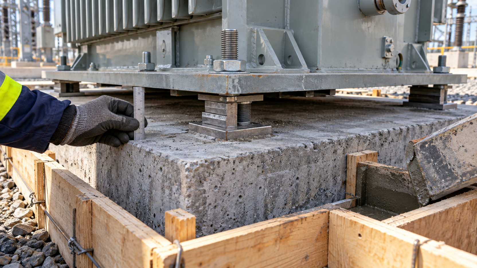
The public scope of ASTM C1107/C1107M concerns packaged dry hydraulic-cement nonshrink grout intended for loaded applications where a reduction below initial placement height is to be avoided. It is a material specification, not a complete transformer installation release procedure. Specify the contract edition and required evidence; do not infer that a product description establishes compliance for the installed support.
Compare proposed materials against the actual gap, length of travel, access and environmental exposure. Have the material supplier review any unusual geometry, aggregate extension or staged placement. A substitution needs more than a similar compressive-strength number. The engineering review should explain whether the original application method and acceptance basis remain valid.
A qualification report describes a material tested under stated conditions. A site placement record describes what was installed. Keep both. The record should connect the approved product to the delivered batch, storage condition, mixing information and identified support. If the contractor changes the product after approval, retain the original selection and the accepted substitution decision.
Do not insert an arbitrary minimum grout thickness or universal waiting period into the purchase specification. Obtain those requirements from the selected product information and responsible design team. Where cementitious and resin-based options are being compared, require each proposal to state its own preparation, temperature and curing requirements rather than merging them into one hybrid method.
The pre-placement inspection is the best opportunity to establish what lies beneath the base. Record support identity, the drawing revision and the observed condition before formwork conceals the interface. Locate any contamination, loose material, inaccessible recess or unexpected obstruction. Resolve its significance before the crew begins mixing.
Sika’s cementitious baseplate grouting method statement calls for sound, clean prepared concrete, appropriate pre-wetting without standing water, controlled mixing water, formwork that retains grout, air escape and curing protection. These are manufacturer instructions for the stated product family. Use the current approved product documents to establish the actual procedure, particularly if another grout chemistry is selected.
The EPC inspector should verify that the preparation record covers the bearing zone rather than only the visible perimeter. Confirm how leveling devices, anchor sleeves and any intentional voids are treated. Photograph accessible areas while they can still be identified. Photographs support the inspection record; they cannot establish hidden dimensions or replace measurements that were never taken.
Agree the consequences of a failed check before placement starts. A missing approval can stop one support or the whole pour depending on the method. Record that boundary. This avoids a last-minute argument about whether the next crew can proceed while the civil designer is still reviewing a discrepancy.
The placement package should make the proposed feed point, sequence and access understandable to someone who did not prepare it. Check that available mixing and delivery arrangements can support the approved method. Confirm who observes the remote edge or outlet and how that observation will be recorded. A completed material delivery does not establish that the installation team is ready.

Identify the conditions that require a pause and engineering review. Examples include unexpected leakage, an interrupted supply, a changed grout gap or an obstruction discovered after formwork installation. The responsible contractor and material supplier should define the response in the approved method. Site personnel should not improvise a different mixture to recover workability or disguise a placement problem.
Record enough information to locate a questionable batch after the work is covered: product identity, batch reference, support location, placement time and the relevant inspection or sampling reference. Keep the record legible and tied to the actual sequence. A delivery note for the whole substation cannot identify which support received a particular batch.
Where the specification requires field tests, agree the sampling and acceptance plan before work begins. The laboratory, contractor and inspector should understand what each result represents. A test performed at a different consistency or under different conditioning should not silently substitute for the evidence required by the project.
“Grouted yesterday” is a date, not a release decision. Define the next activity: removal of temporary supports, final anchor operations, additional equipment assembly or another planned load change. Each may have a different prerequisite. State the conditions in the inspection and test plan before the programme depends on them.
The reviewer needs both the specified material evidence and the installed-support inspection. A satisfactory strength result does not explain whether the intended space was filled. Conversely, an attractive finished shoulder does not prove strength development. Retain the curing and protection record with the results so the approving engineer can understand the conditions under which the material developed.
Temporary supports deserve a positive disposition. Identify which remain permanently, which are removed and who authorizes that step. Do not assume that grouting automatically permits removal of all leveling devices. Equally, do not leave temporary items in place merely because they are difficult to reach; their final role must agree with the approved support design.
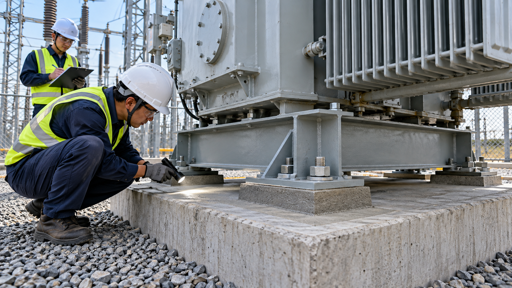
Map an observed crack, gap, damaged edge or suspected void to the support drawing. Describe its location and extent without declaring a cause from appearance alone. Distinguish an accessible surface observation from an unverified condition beneath the plate. The engineer can then decide whether additional investigation is needed and what evidence would answer the question.
Keep repair proposals under controlled review. A surface patch should not be accepted as proof that an internal bearing deficiency has been corrected. If a repair alters the support condition, coordinate the equipment supplier, structural designer and material specialist before implementation. Use the established transformer design change process when drawings or assumptions change.
For example, consider an installation whose material test results satisfy the specified criterion but whose placement log reports leakage at one support. The useful decision is not an automatic acceptance or rejection. First locate the affected area, establish what evidence is missing and obtain a documented disposition. The example illustrates review logic; it is not a report of a Zisheng Electric project.
Organize the final package by support identity. Include the approved detail, material approval, pre-placement inspection, placement record, required results, curing record, deviations and final release. Keep the actual limits and approval signatures with the record rather than referring to an unspecified “standard procedure.” The owner should be able to understand which activity was released and which restrictions remained.
Record the accepted condition before subsequent work hides access. Coordinate any remaining foundation survey or equipment alignment work with the relevant discipline. Grout acceptance does not close unrelated cable, protection, earthing or commissioning requirements, and it should not be labelled as permission to energize the transformer.
For packages using a 35–46 kV power transformer or a 10 kV class oil-immersed distribution transformer, establish the actual mounting arrangement early. Product ratings alone cannot determine the base detail, civil bearing requirements or installation sequence.
Send Zisheng Electric the equipment drawings, civil sections, data sheets, load list, technical specification, single-line diagram, grid parameters, environmental conditions and installation-site constraints. Include the proposed support and grout details, scope boundaries and unresolved decisions so the transformer baseplate grouting review can address the real equipment interface. Our engineering team will review the requirements and respond to project inquiries within 24 hours.
Plan substation HMI mimic acceptance with equipment labels, status interpretation, measurement meaning, data-quality checks and controlled handover records.
View details
Build a substation cable drum schedule linking route take-off, approved cut lengths, drum allocation, stock balances and installation release for EPC projects.
View details
Transformer vector group selection guide for EPC substations covering phase shift, grounding, zero-sequence behavior, protection, parallel operation, FAT and site phasing.
View details
Build a transformer SFRA baseline package for EPC handover: align test configurations, preserve raw files and resolve comparison gaps before release.
View details