 zishengelectric



news
News Center
Providing high-quality power to the world
Search productSearch post
news
Providing high-quality power to the world
Before energization, EPC commissioning teams should confirm that the transformer core’s intended ground connection is intact and that no second unintended path has formed. This is different from grounding the transformer neutral or tank. Zisheng Electric recommends treating the core-ground inspection as a controlled, manufacturer-led check whenever the project procedure requires it, rather than adding an improvised megger step to a generic commissioning form.
Transformer magnetic cores and associated metallic structures are normally insulated from the tank except for the intentional connection defined by the design. An additional accidental ground can create an unintended conductive loop; induced voltage in that loop may produce circulating current, localized heating and insulation damage. The exact construction and test points vary by transformer, so the approved drawings and manufacturer’s instructions govern the check.
Do not confuse this internal core-ground path with the system neutral grounding conductor. Neutral grounding determines the power-system earth-fault path and protection duty. Core grounding is a construction and condition-monitoring issue inside the transformer. The two should be separately identified on the interface drawings and in test records.
A core-ground test must never be performed by opening a grounding connection on an energized transformer. Do not inject current, burn off a suspected ground or remove internal links as a field experiment. Those actions can create safety hazards and damage insulation; escalation belongs with the asset owner and transformer manufacturer.
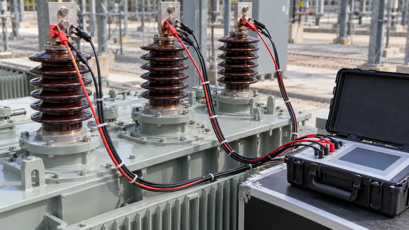
If the approved method calls for insulation-resistance measurement from the accessible core-ground point to earth, follow the test voltage, duration and connection arrangement specified by the manufacturer and project procedure. There is no safe universal acceptance threshold to paste into every transformer checklist. Design details, accessible insulation sections, test connections, instrument method and prior factory baseline all matter.
Record the identified test point, whether the intended ground link was opened, other winding and tank connection states, test instrument and voltage, duration, measured value, temperature and humidity where required, and the reference acceptance criterion. Compare the result with the factory or commissioning baseline under a comparable configuration. A very low reading or a result that differs materially from the agreed baseline should be treated as an investigation trigger, not automatically diagnosed as a core fault.
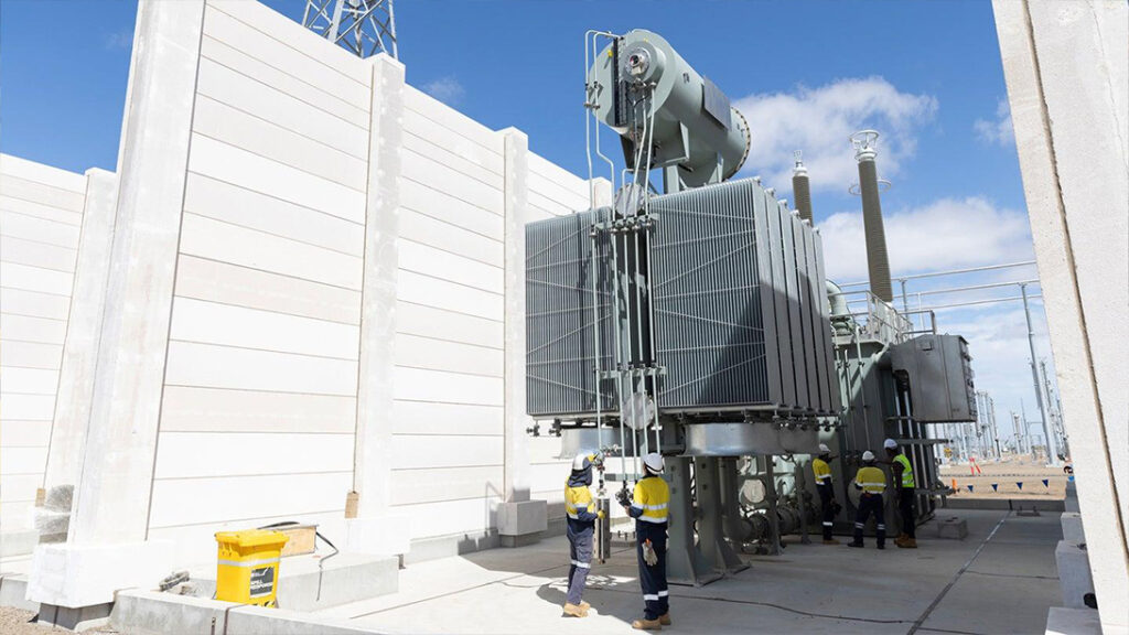
First verify that the correct core lead and test point were identified. Check the drawing revision and physical tags. Then review whether temporary test leads, instrumentation, shipping braces, grounding straps or accessory wiring could have created a parallel path. The manufacturer should advise which parts are intentionally bonded and which must remain insulated for the test.
If the approved measurement suggests an unexpected ground, stop before dismantling anything. Repeat only when the procedure allows, verify instrument setup and connection state, and compare the result with other evidence such as core-ground current trends, dissolved-gas results, oil condition or thermal observations. The U.S. Bureau of Reclamation’s transformer maintenance guide notes that an unintended core ground can create circulating currents; IEEE C57.152-2025 is the current IEEE guide for diagnostic field testing of liquid-filled transformers and advises interpreting test results together and consulting manufacturer acceptance criteria.
After the test, restore the approved intentional core-ground connection, apply the specified hardware and torque, and verify continuity to the designated earth point. Independently check that temporary links and leads have been removed, the test point cover is secured, and the final connection matches the released drawing. Record who restored and witnessed the state; this is a safety-critical handover item.
For the wider energization boundary, align this check with the transformer site acceptance checklist. Keep it separate from the transformer neutral grounding design, which addresses system fault-current and protection requirements. Product drawings and the approved technical data for a 10 kV oil-immersed transformer should identify the project-specific connection arrangement.
For field diagnostics, consult the applicable current edition of IEEE C57.152-2025 and the U.S. Bureau of Reclamation transformer maintenance and diagnostics guide, together with the transformer manufacturer’s procedure and the project acceptance plan. If your commissioning team has an unexplained core-ground reading, share the approved drawing, test configuration and baseline report with Zisheng Electric for an engineering review before any corrective action is attempted.
Full-cycle EPC transformer service covering design freeze, manufacturing, FAT, overseas logistics, on-site installation and commissioning for Middle East and Africa power projects.
View details
Build a transformer DGA baseline for EPC handover: connect oil history, sample identity, laboratory methods and first-service review responsibilities.
View details
Plan a transformer first-service thermal survey with safe access, representative load records, cooling checks, evidence ownership and clear EPC handover decisions.
View details
A field-focused EPC guide to transformer cable termination interfaces, covering bushings, cable boxes, clearances, earthing, FAT checks and commissioning handover.
View details