 zishengelectric



news
News Center
Providing high-quality power to the world
Search productSearch post
news
Providing high-quality power to the world
Transformer pressure relief discharge routing is an interface that can fall between an equipment purchase order and the site piping package. Zisheng Electric treats that boundary as an engineering coordination item: the selected protective device, its discharge arrangement and the surrounding substation must be reviewed together. A satisfactory accessory data sheet alone does not establish where released fluid will go, who supplies the connecting parts or how the installed arrangement will be accepted.
For an EPC team, the useful starting point is a continuous trace from each pressure relief device to its approved discharge destination. Follow that trace through the equipment drawing, mechanical arrangement, civil containment plan and protection documentation. This article sets out a procurement and handover review method for oil-immersed transformers. It is not a universal piping design or a procedure for testing a pressurized transformer.
Begin by identifying which compartment each device protects. The main tank and a separate tap-changer compartment may have different arrangements. Record the device tag, compartment, manufacturer, ordered version and drawing reference. Do not combine outlets simply because they appear close together on the general arrangement. Any common discharge arrangement requires explicit engineering acceptance for the selected equipment.
Next, distinguish a directional shield from a complete collection system. Qualitrol describes its XPRD pressure relief device as having an integrated directional discharge outlet, while fluid containment requires optional piping. That distinction matters commercially: a purchase order that mentions a directional outlet may still leave the downstream route outside the supplier’s scope.
Mark the physical supply boundary on a drawing. It may be a flange, a proprietary connection or another manufacturer-defined interface. State who provides the mating component, seals, fasteners, supports and site assembly instructions. A sentence saying “all accessories included” is too ambiguous to settle those responsibilities when different contractors supply the transformer and containment works.
The transformer manufacturer should establish the pressure relief arrangement for the tank design and ordered service. EPC reviewers need the approved device schedule and installation instructions before they release connecting pipework. The operating setting, device count, outlet configuration and permitted installation orientation are equipment-specific information. They should not be copied from an earlier project merely because the new transformer has a similar rating.
The Reinhausen VST/VST2 operating instructions describe a spring-loaded valve and versions with directed oil-flow connections. They also show that indication and contact reset behaviour differ between versions. These are reasons to obtain the exact ordered manual; they are not a basis for assuming every pressure relief accessory behaves identically.
Ask the supplier to identify the design information needed to accept the proposed downstream route, including any relevant limits on restriction, backpressure, geometry or connection loads. When a limit is absent from the available documentation, raise a technical query. An absent number is not permission to choose a convenient value. Keep unresolved items visible on the drawing review register until the responsible designer provides an answer.
The release record should identify the approved revision rather than simply stating that a catalogue was submitted. If an accessory is substituted after procurement, reopen the interface review. A change in outlet position can affect the spool, while a change in contact arrangement can affect the protection drawing even when the replacement device appears mechanically similar.
Trace the route through the actual equipment arrangement. Include radiators, cooler frames, conservator supports, cable boxes, ladders, marshalling cabinets and removable maintenance components. A line that fits on a two-dimensional elevation can obstruct a cabinet door or a radiator removal path in the completed installation. Use dimensions and access envelopes, not an attractive perspective alone, to close the review.
The endpoint must be deliberately selected. Coordinate it with the responsible civil and fire-protection designers so that a discharge is not directed toward an operating position, escape route or vulnerable adjacent equipment. The approved destination and any collection arrangement must remain compatible with the device manufacturer’s requirements. Do not assume that placing an outlet somewhere above a bund automatically settles every discharge and containment question.
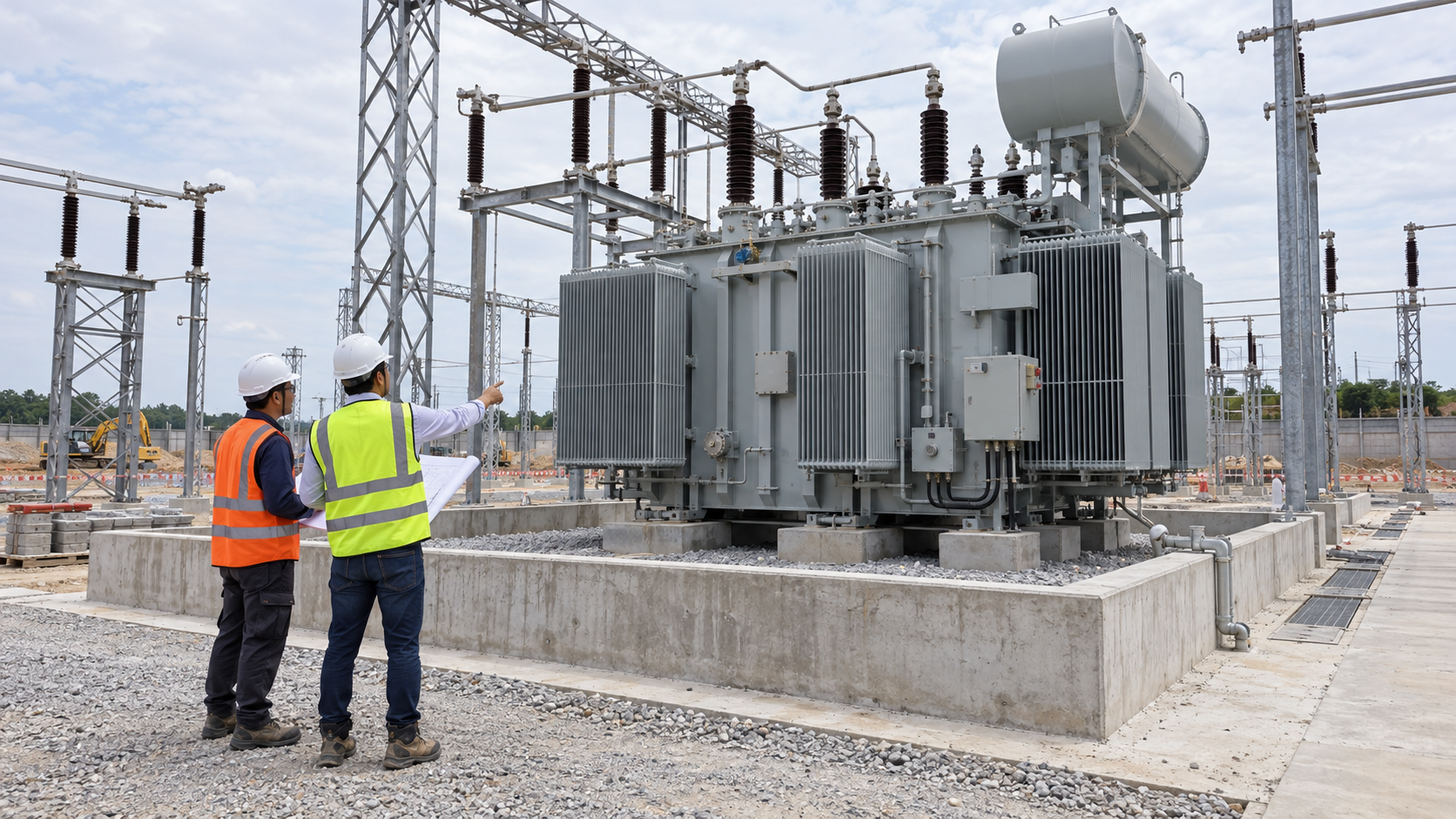
Consider what can change after installation. Later cable trays, fencing, screens and small buildings can occupy space that was clear during transformer procurement. Place the accepted routing envelope on the coordinated site drawings. This gives future modifications a concrete interface to check instead of relying on the memory of the original commissioning team.
Review local exposure as part of the route definition. Rain, dust, corrosion, freezing conditions where relevant and potential physical impact can affect the proposed arrangement. The response must be an approved design detail. An improvised cap, screen or valve added to keep debris out could alter the intended discharge function; it should never be accepted solely because it makes the installation look tidier.
A containment calculation addresses a different question from accessory performance. Both must be coordinated, but neither replaces the other. Our guide to transformer oil containment design for EPC substations provides the wider civil interface context. For this review, identify the exact discharge destination on that civil arrangement and record who accepts the connection between the two systems.
A useful register identifies an owner, a decision and an acceptance record. The following table is a review framework, not a set of universal technical limits. Assign the named organizations in the project responsibility matrix; the typical leads below may change with the contract.
| Interface | Decision required | Typical lead | Evidence before release |
|---|---|---|---|
| Device and protected compartment | Confirm the ordered version and approved application | Transformer manufacturer | Device schedule, manual and approved drawing revision |
| Outlet and mating parts | Define connection geometry and supply boundary | Equipment and mechanical package leads | Interface drawing and itemized supply list |
| Route and restrictions | Accept the proposed geometry for the selected device | Responsible equipment designer | Closed technical queries and route approval |
| Supports and movement | Allocate loads and allow approved assembly tolerances | Mechanical and structural designers | Support details and verified site dimensions |
| Destination and access | Coordinate discharge, containment and personnel routes | Civil, fire and operations reviewers | Coordinated layout with accepted endpoint |
| Signals and handover | Confirm cause-and-effect and indication behaviour | Protection and commissioning leads | Approved wiring, test records and operator instructions |
Use explicit hold points for unresolved items that affect safe function or prevent correct assembly. Other documentation comments may be closed through a controlled punch list. The project team should define that distinction before shipment; a generic “accepted with comments” stamp gives the site little guidance about what it may actually install.
Connecting pipework introduces mechanical interfaces as well as a flow path. Establish how its weight and any applicable movement loads are carried, and what loads the device connection is permitted to receive. The installation should follow the approved support scheme. Pulling a misaligned spool into place with flange bolts is not an acceptable substitute for resolving dimensional differences with the responsible designer.
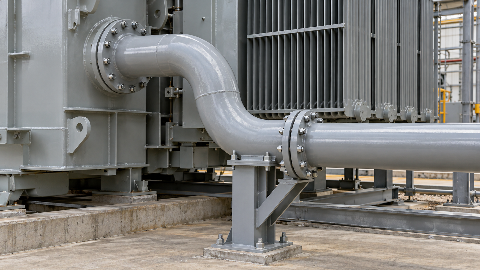
For transport, identify which sections remain attached and which are shipped loose. Match each loose item to a packing-list reference and installation drawing. Record the required seals and fasteners, their storage arrangements and the party responsible for replacing damaged items. This avoids a common handover gap in which a spool arrives but the site cannot identify the correct joint components.
Factory review should check the portions that actually exist at the factory. Site-only sections need their own acceptance evidence after assembly. A factory photograph cannot verify a field joint that has not yet been made. Similarly, a completed factory accessory check does not confirm that later site work left the discharge path unobstructed.
At site, authorized personnel should compare the installed route with the accepted revision, inspect the mechanical condition and confirm that shipping protections have been dealt with exactly as instructed. Record deviations before energization readiness is declared. Any proposed pressure or functional testing must follow an approved manufacturer-supported procedure and the site’s safety controls; this article does not prescribe test pressure or methods.
The mechanical route and the electrical response require separate verification. Identify each contact, its terminal reference, expected state and destination in the protection system. The applicable manufacturer instructions and approved cause-and-effect determine the required response. Do not downgrade a required trip into an alarm for commissioning convenience, or assume a momentary and a latched indication can use the same logic without review.

The VST/VST2 manual, for example, includes specific requirements for the tripping circuit and distinguishes the reset behaviour of its versions. The practical procurement lesson is to carry the ordered device identity into the wiring schedule and commissioning checklist. Record the approved method used to verify the signal chain; a local indication check alone does not demonstrate the full response through the receiving system.
Operator instructions should explain how an indication is reported, investigated and handed to authorized personnel. They should not encourage a reset before the cause has been assessed under the applicable procedures. Include access requirements and the location of relevant drawings in the maintenance dossier, so the team does not have to reconstruct the accessory interface during an abnormal event.
Coordinate this handover with the broader transformer fire-protection interface review. A pressure relief device is one part of an overall protection arrangement. Its presence must not be presented as a guarantee that an internal fault cannot lead to equipment damage or a fire.
Consider an illustrative EPC coordination issue: a discharge spool conflicts with a late cable-tray support. The field proposal is to add two bends and move the outlet. That proposal changes more than clearance. It changes the geometry previously accepted by the equipment designer and may move the discharge destination closer to a walkway.
The useful response is a marked-up route drawing showing the revised dimensions, support locations and endpoint, followed by equipment and site-discipline review. Record the approved solution and update the installation package before fabrication proceeds. If an alternate route cannot be accepted promptly, the project manager needs a visible hold point and schedule impact, not an undocumented field modification concealed by a final photograph.
This example is a coordination scenario rather than a claim about a delivered customer project. Its value is the decision sequence: identify the changed interface, obtain the required technical acceptance and carry that acceptance into the as-built record. The same sequence applies when the device itself changes or when the civil containment layout is revised.
Provide the transformer arrangement and the site’s surrounding constraints early enough for joint review. For projects considering Zisheng Electric 35kV and 46kV power transformers or 110kV and 115kV power transformers, request an accessory interface schedule alongside the principal electrical data. The ordered configuration and approved design documents determine the final arrangement.
Include drawings, data sheets, the load list, technical specification, single-line diagram, grid parameters, environmental conditions and installation-site constraints. For transformer pressure relief discharge routing, add the containment layout, access routes, proposed supply split and protection interface requirements. These inputs allow unresolved boundaries to be identified while the equipment and site designs can still be coordinated. Our engineering team will review the requirements and respond to project inquiries within 24 hours.
Review the substation surge arrester interface for EPC projects: insulation coordination, placement, lead and earth paths, procurement boundaries, installation checks and documented handover.
View details
Coordinate transformer fire protection interfaces for EPC substations, including fire walls, oil containment, detection, suppression, breaker trips, SCADA, integrated testing and handover evidence.
View details
A field-focused EPC guide to transformer cable termination interfaces, covering bushings, cable boxes, clearances, earthing, FAT checks and commissioning handover.
View details
Coordinate transformer fire protection for EPC projects: separation, oil containment, drainage, detection, suppression, control logic, FAT and site testing.
View details