 zishengelectric





news
News Center
Providing high-quality power to the world
Search productSearch post
news
Providing high-quality power to the world
Transformer vector group selection is not a nameplate detail to be copied from a previous project. It determines phase displacement, whether a neutral is available, how zero-sequence current can flow, which protection studies remain valid and whether two transformers can operate in parallel. For an EPC substation, the correct choice begins with the system earthing philosophy and load behavior, then closes the interfaces among the utility, transformer supplier, protection engineer and commissioning team.

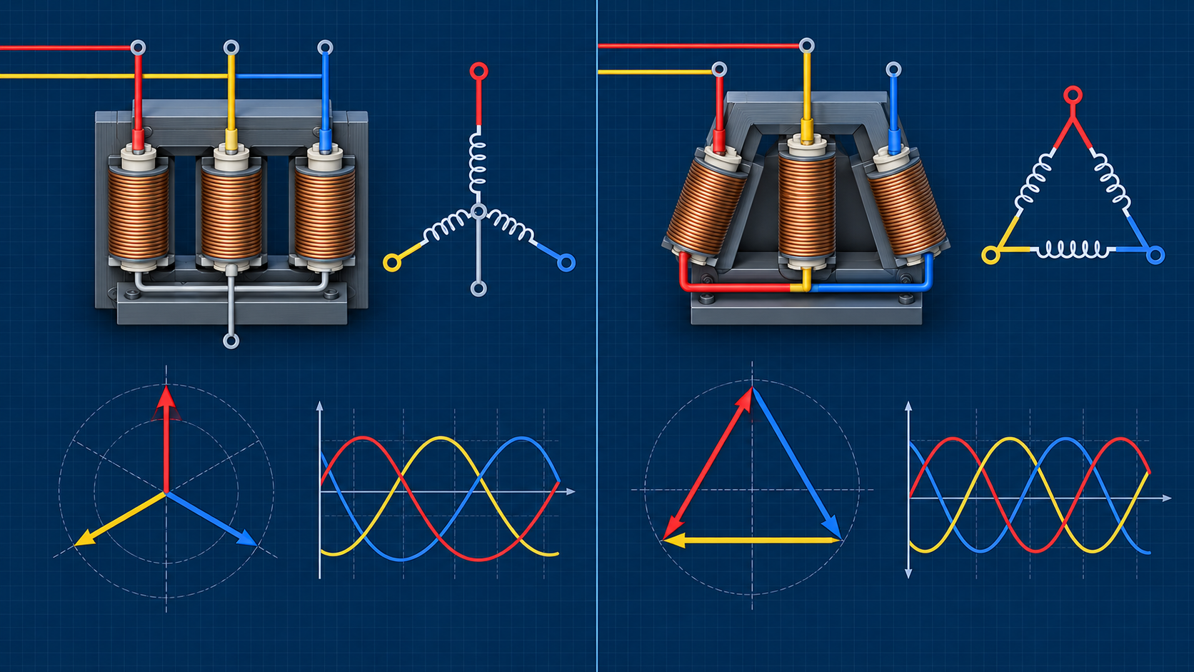
A vector group code describes the winding connections and the angular displacement between high-voltage and low-voltage line-voltage phasors. Letters identify star, delta or zigzag connections; the neutral suffix shows whether a star or zigzag neutral is brought out; and the clock number expresses the displacement in 30-degree steps. The notation is compact, but its engineering consequences are extensive.
The selected connection establishes a path—or deliberately removes a path—for zero-sequence current. It affects earth-fault current magnitude, relay sensitivity, third-harmonic circulation, neutral loading, voltage behavior during unbalanced faults and compatibility with existing transformers. A mismatch discovered after manufacture can require network redesign, auxiliary transformers or a replacement unit. The vector group therefore belongs in the approved datasheet, single-line diagram, protection basis and FAT schedule.
The IEC 60076-1 power transformer standard provides the general framework for transformer ratings, connection symbols and test requirements. The IEC 60076-8 application guide covers service characteristics of transformer connections, zero-sequence phenomena and parallel operation. Project specifications should cite the applicable edition and state project-specific values rather than relying on the standard title alone.
The first question is whether each voltage level needs a grounded neutral and, if it does, how that neutral will be grounded. A star winding with an accessible neutral can support solid, resistance or reactance grounding. A delta winding has no external neutral, although it may provide a closed path for circulating triplen harmonics and can block zero-sequence current from transferring as line current to the other system.
Record the source grounding, downstream grounding, neutral earthing resistor data, single-line-to-ground fault duty and protection clearing time. Coordinate these inputs with the published guidance on transformer neutral grounding design. The transformer connection must not create an unintended second ground or leave a system expected to be grounded without a dependable reference.
Large motors, rectifiers, variable-frequency drives, data-center loads and renewable-energy converters can influence connection choice. A delta may provide a local path for some zero-sequence and triplen components, but it is not a substitute for a harmonic study. A four-wire low-voltage system normally needs a neutral with adequate continuous and fault-current capability. The EPC team should identify unbalanced single-phase loading, expected neutral current and any converter supplier requirements before selecting a winding arrangement.
| Engineering question | Evidence required | Vector-group consequence | Release check |
|---|---|---|---|
| Is a load-side neutral required? | Single-line diagram, load schedule, grounding study | Select a star or zigzag winding with the neutral brought out where needed | Neutral rating and terminal are stated |
| Must zero-sequence current transfer across the transformer? | Sequence-network model and earth-fault study | Winding and core arrangement must support the intended path | Zero-sequence assumptions are supplier-reviewed |
| Will units operate in parallel? | Existing nameplates, ratio, impedance and tap data | Phase displacement, sequence and polarity must be compatible | Parallel-operation study is approved |
| Are nonlinear or unbalanced loads material? | Harmonic spectrum and phase-loading forecast | Connection must be coordinated with neutral and thermal design | Loss and temperature inputs are agreed |
| Does protection depend on residual quantities? | Relay philosophy, CT connections and fault simulations | Vector compensation and zero-sequence filtering must match | Relay settings and drawings share one reference |
| Is the utility phase sequence fixed? | Grid code and interface confirmation | Terminal marking and displacement must match the point of connection | Phasing test is included in commissioning |
Matching vector-group symbols is necessary for conventional parallel operation, but it is not sufficient. The two units also need compatible polarity, phase sequence, voltage ratio, tapping range and impedance. Large impedance differences cause unequal load sharing. Ratio or tap-position differences can drive circulating current even when the external load is modest. Differences in X/R ratio influence how active and reactive components divide.
For an extension project, obtain readable nameplate photographs and certified test reports for every existing transformer. Do not infer the clock number from old drawings alone. Compare ratio at the intended operating tap, measured impedance on a common MVA base, cooling rating and neutral-grounding arrangement. If deliberate non-parallel operation is intended, document the interlock that prevents bus couplers or transfer schemes from closing incompatible sources together.
A useful specification separates “capable of supplying the same bus” from “approved for continuous parallel operation.” The latter requires a documented study and commissioning test. The substation pre-energization readiness review should confirm phasing, bus-coupler logic and the authorized switching state before the first energization.
Differential protection normally compensates for transformer phase displacement and may remove zero-sequence components internally. The relay setting must use the final vector group, not an early tender assumption. CT orientation, ratio and star-point location also have to align with the approved protection diagram. A wrong clock number or swapped phase can produce spill current during normal load and make a correct relay appear defective.
Earth-fault and restricted-earth-fault functions depend on whether a neutral exists and where current transformers are installed. The zero-sequence network used in the short-circuit study must represent the transformer’s winding connections, neutral impedance and magnetic circuit. When a delta tertiary is provided, define whether it is stabilizing only, rated for auxiliary loading or available for external connection. Its thermal and fault duties must be explicit.

The tender datasheet should state rated voltages, rated power, frequency, vector group, highest voltage for equipment, insulation levels, tapping range, impedance, neutral insulation and neutral current rating. Include the system phase sequence and terminal orientation viewed from a defined side of the transformer. State whether the neutral terminal requires a bushing CT, surge arrester, grounding conductor interface or removable link.
Make the vector group a controlled field across the single-line diagram, equipment datasheet, general arrangement, terminal plan, protection schematic, cable schedule and relay setting file. The workflow described in transformer datasheet approval for EPC projects helps prevent a late change from propagating inconsistently through manufacturing and site documents.
Product selection should follow the approved electrical requirements. Zisheng Electric can review the connection and interface data for a 2500 kVA oil-immersed transformer, a higher-voltage 220 kV/230 kV power transformer or a packaged prefabricated compact substation. These links show product families; final ratings, connection, insulation and accessories remain project-specific and subject to engineering confirmation.
At FAT, ratio and phase-displacement tests should verify the declared connection symbol at the applicable tap positions. Winding-resistance, insulation and routine electrical tests provide additional evidence that the manufactured unit matches the approved design. The witness plan should identify the governing procedure, acceptance criteria, calibrated instruments and record format before testing begins.
Review the terminal markings against the approved drawings and photograph the nameplate, terminal arrangement and test connections. For a unit intended to parallel with an existing transformer, compare the new factory results with the existing certified data before shipping. FAT cannot reproduce the complete site network, so it should close manufacturing evidence while preserving a clearly defined site-phasing test.
Before energization, verify phase sequence from the source through the transformer to the destination bus. Check the installed tap position, neutral connection, earthing conductor, CT polarity, relay compensation settings and interlocks. Where two supplies can be paralleled, perform an approved phasing comparison across the open coupling device before any close command is permitted.
Use a signed checklist that records instrument identification, test conditions, measured phase relationships and responsible parties. If a discrepancy appears, stop the energization sequence and reconcile the single-line diagram, cable terminations, terminal markings and test data. Field swapping of phases may change the effective system relationship and protection references; it requires engineering approval and controlled drawing updates.

A vector-group change after design freeze is a system change, even when the transformer dimensions and price appear unaffected. The engineer should reopen the short-circuit, load-flow, grounding and protection studies and identify every drawing or software file that used the previous connection. Typical affected records include the single-line diagram, sequence-network model, differential relay compensation, residual-current logic, metering phasor assignment, synchronism-check settings, cable core schedule and switching procedure. The review should also consider whether auxiliary supplies or station-service transformers derive a neutral from the affected bus.
Issue the change through a numbered technical query or deviation request that states the reason, old value, new value, affected interfaces and approval owners. Manufacturing should not implement the change until the EPC engineer, network owner and protection authority agree on the same revision. If manufacture has already started, the supplier should identify consequences for winding arrangement, leads, terminal locations, insulation clearances, neutral equipment, routine-test procedure and delivery date. Commercial acceptance alone is not technical acceptance.
The final document register should show one consistent vector group across the approved datasheet, nameplate drawing, terminal marking plan, protection drawings, relay files, FAT report and as-built package. During handover, operations personnel need the approved parallel-operation restrictions and switching interlocks, not only the transformer manual. This traceability matters when a future replacement unit is procured: an exact, verified connection record prevents the next project from repeating assumptions that were never validated.
A robust transformer vector group selection connects network grounding, load characteristics, zero-sequence behavior, protection logic and operating philosophy. The EPC team should freeze it only after the relevant studies are aligned, verify it during FAT and confirm real bus phasing before energization. That sequence converts a short nameplate code into a controlled system interface.
Send Zisheng Electric the single-line diagram, grounding study, fault levels, load schedule, existing transformer data and parallel-operation requirements for an engineering review. Our engineering team will review the requirements and respond to project inquiries within 24 hours.
Coordinate transformer earthing interfaces for EPC projects: tank bonds, neutral grounding, core links, cable screens, surge arresters, FAT and handover.
View details
Build a transformer protection interface matrix covering CTs, relays, trips, alarms, SCADA, auxiliary power, FAT and commissioning responsibilities.
View details
Coordinate transformer protection interfaces for EPC projects, including CT inputs, mechanical trips, alarms, relay logic, SCADA, FAT and handover.
View details
Build a transformer SFRA baseline package for EPC handover: align test configurations, preserve raw files and resolve comparison gaps before release.
View details