The 110kV / 115kV Power Transformer is a high-voltage oil-immersed transformer designed for power transmission, substation and large-scale industrial applications.
It is used to step up or step down electrical energy between high-voltage transmission networks and medium-voltage distribution systems. The transformer can be engineered according to project requirements for rated capacity, voltage ratio, impedance, vector group, tap range, cooling system, insulation level and installation conditions.
Typical applications include:
- Utility substations
- Power generation plants
- Transmission networks
- Industrial substations
- Mining projects
- Oil & gas facilities
- Renewable energy projects
- Large commercial and industrial parks
- Grid interconnection projects
The design can be supplied according to IEC, IEEE/ANSI, GB or customer-specific technical specifications.
2. Main Technical Specifications
| Parameter |
Typical Specification |
| Product Type |
Oil-Immersed Power Transformer |
| Rated Voltage |
110kV / 115kV |
| Rated Capacity |
10MVA–240MVA or customized |
| Frequency |
50Hz / 60Hz |
| Phase |
Three Phase |
| High Voltage |
110kV / 115kV |
| Medium Voltage |
6.3kV / 10kV / 10.5kV / 11kV / 13.8kV / 33kV / 34.5kV or customized |
| Low Voltage |
0.4kV / 0.415kV or customized where applicable |
| Cooling |
ONAN / ONAF / OFAF / ODAF |
| Tap Changer |
OLTC / Off-Circuit Tap Changer |
| Tap Range |
Typically ±8×1.25%, ±10×1.25% or customized |
| Vector Group |
Dyn11 / YNd11 / YNd1 / customized |
| Winding Material |
Copper / Aluminum |
| Insulating Medium |
Mineral Transformer Oil / Ester Fluid |
| Tank Type |
Conservator / Sealed Tank |
| Installation |
Outdoor / Indoor Substation |
| Insulation |
Oil-Paper Insulation System |
| Standard |
IEC 60076 / IEEE / ANSI / GB or customized |
| Altitude |
≤1000m standard / customized |
| Ambient Temperature |
Customized according to project |
| Lightning Impulse |
According to insulation coordination |
| Impedance |
Project-specific |
| Neutral |
Solidly grounded / resistance grounded / customized |
Note: Rated capacity, impedance, insulation level, tap range and cooling arrangement should be finalized according to the customer's technical specification rather than using one fixed value for every 110kV/115kV transformer.
3. Typical Voltage Configurations
The transformer can be manufactured with different voltage combinations according to grid requirements.
Typical configurations
- 110 / 11kV
- 110 / 13.8kV
- 110 / 33kV
- 110 / 10.5kV
- 115 / 13.8kV
- 115 / 11kV
- 115 / 34.5kV
- 115 / 33kV
- 110 / 10.5 / 0.4kV
- 115 / 13.8 / 0.4kV
- Other customized voltage ratios
For utility and EPC projects, the HV/MV voltage ratio, neutral arrangement, vector group and grounding method should be confirmed during technical design.
4. Rated Capacity
Typical capacity ranges include:
- 10 MVA
- 16 MVA
- 20 MVA
- 25 MVA
- 31.5 MVA
- 40 MVA
- 50 MVA
- 63 MVA
- 80 MVA
- 100 MVA
- 120 MVA
- 150 MVA
- 180 MVA
- 200 MVA
- 240 MVA
Custom capacity available according to project requirements.
For large transmission and substation projects, higher-capacity transformers can be engineered according to system load, short-circuit level, transportation limitations and installation conditions.
5. Transformer Construction
Core
The transformer uses a high-quality laminated silicon-steel core designed to reduce no-load losses and magnetizing current.
The core structure is optimized to:
- Reduce magnetic flux leakage
- Minimize no-load losses
- Reduce operating noise
- Improve thermal performance
- Increase long-term operating reliability
HV Winding
The high-voltage winding is designed specifically for 110kV/115kV insulation requirements.
The winding structure can be optimized for:
- Electric field distribution
- Lightning impulse withstand
- Short-circuit mechanical strength
- Temperature rise
- Insulation reliability
For high-voltage transformers, winding and insulation design are critical because IEC 60076-3 specifies dedicated dielectric requirements for transformers in this voltage range.
LV / MV Winding
The medium- and low-voltage windings are designed according to the required output voltage and load characteristics.
Copper or aluminum conductors can be selected according to:
- Rated current
- Loss requirements
- Short-circuit withstand capability
- Customer specification
- Project budget
6. Insulation System
The transformer uses an oil-paper insulation system consisting of:
- Transformer oil
- Insulating paper
- Pressboard
- Cylinders
- Insulating barriers
- End insulation
- Inter-layer insulation
The insulation system is designed to withstand:
- Normal operating voltage
- Temporary overvoltage
- Lightning impulses
- Switching impulses where applicable
- Short-duration power-frequency voltage
For the 72.5kV–170kV equipment range, IEC 60076-3 includes full-wave lightning impulse and applied-voltage tests among the applicable dielectric requirements.
7. Cooling System
Different cooling configurations are available depending on transformer capacity.
ONAN
Oil Natural Air Natural
Natural circulation of transformer oil and air.
Suitable for standard operating conditions and lower-capacity transformers.
ONAF
Oil Natural Air Forced
Natural oil circulation with forced-air cooling.
Suitable for higher-capacity transformers and increased loading requirements.
OFAF
Oil Forced Air Forced
Forced oil circulation combined with forced-air cooling.
ODAF
Oil Directed Air Forced
Directed oil circulation and forced-air cooling for high-capacity transformers.
Cooling systems can be configured with:
- Radiators
- Cooling fans
- Oil pumps
- Oil flow indicators
- Temperature controllers
- Automatic fan control
- Cooling system monitoring
8. Tap Changer
The 110kV/115kV transformer can be equipped with an On-Load Tap Changer (OLTC) to regulate the output voltage while the transformer is energized.
Typical configuration:
HV winding + OLTC
Typical tap ranges may include:
- ±8 × 1.25%
- ±10 × 1.25%
- ±12 × 1.25%
- Customized tap range
The actual tap range and tap position depend on the grid voltage regulation requirements.
9. Transformer Tank
The transformer tank is manufactured from high-strength steel and designed to withstand:
- Vacuum conditions
- Internal pressure
- Transportation loads
- Oil expansion
- Environmental exposure
- Long-term outdoor operation
The tank can be supplied with:
- Conservator
- Radiators
- Oil filling valve
- Drain valve
- Sampling valve
- Pressure relief device
- Oil level indicator
- Lifting lugs
- Jacking points
- Grounding terminals
- Temperature indicators
10. Protection & Monitoring Accessories
Depending on the project requirements, the transformer can be equipped with:
Standard / Optional Accessories
- Buchholz relay
- Oil temperature indicator
- Winding temperature indicator
- Magnetic oil level gauge
- Pressure relief device
- Sudden pressure relay
- Oil flow indicator
- Silica-gel breather
- Conservator tank
- OLTC
- OLTC motor drive mechanism
- HV bushings
- MV bushings
- Neutral bushing
- Current transformers
- Cooling fans
- Oil pumps
- Online temperature monitoring
- Online dissolved gas monitoring
- Transformer monitoring system
11. Safety & Protection
The transformer can incorporate multiple protection systems to improve operational safety.
Buchholz Protection
Detects gas accumulation and oil flow caused by internal transformer faults.
Pressure Relief Protection
Provides rapid pressure release in case of abnormal internal pressure.
Temperature Protection
Monitors:
- Top oil temperature
- Winding temperature
- Cooling system status
Oil Level Monitoring
Provides continuous monitoring of transformer oil level.
OLTC Protection
The OLTC can be equipped with dedicated protection and monitoring devices.
12. Performance Advantages
01. High Voltage Reliability
Designed for 110kV and 115kV transmission and substation applications with appropriate insulation coordination and dielectric testing.
02. Low Loss Design
Optimized magnetic core and winding design help reduce no-load and load losses.
03. Strong Short-Circuit Capability
Mechanical strength of windings and clamping structures is designed to withstand the electromagnetic forces generated during short-circuit conditions.
04. Efficient Cooling
Multiple cooling configurations are available for different capacity and loading requirements.
05. Flexible Voltage Design
HV, MV, LV, tap range and vector group can be customized according to the grid specification.
06. Long Service Life
High-quality core materials, insulation components, transformer oil and sealing systems support reliable long-term operation.
07. Global Project Adaptability
Design parameters can be coordinated with different international grid standards and project specifications.
13. Routine Testing
Each transformer should undergo the required routine tests before shipment.
Typical tests include:
- Winding resistance measurement
- Voltage ratio measurement
- Phase displacement verification
- Short-circuit impedance measurement
- Load loss measurement
- No-load loss measurement
- No-load current measurement
- Applied voltage test
- Induced voltage test
- Lightning impulse testing where specified
- OLTC operational test
- Transformer oil testing
- Tank leakage test
- Pressure test
- Bushing inspection
- Control circuit inspection
- Protection device verification
- Temperature indicator verification
IEC 60076-1 identifies winding resistance, ratio/phase displacement, short-circuit impedance/load loss, no-load loss/current and dielectric tests among the routine testing framework.
For high-voltage projects, the purchaser can additionally specify tests such as partial discharge, frequency response analysis (FRA), temperature-rise testing, acoustic/noise testing and short-circuit withstand testing, depending on the project specification.
14. Type & Special Tests
For utility and EPC projects, additional testing can be arranged according to the purchase specification.
Type Tests
- Temperature-rise test
- Lightning impulse test
- Switching impulse test where applicable
- Sound level test
Special Tests
- Partial discharge test
- FRA test
- Zero-sequence impedance test
- Capacitance and tan delta
- Insulation resistance
- Short-circuit withstand test
- No-load loss at specified voltage levels
- Oil quality testing
- DGA
- Special mechanical tests
IEC 60076 testing is generally divided into routine, type and special testing categories, with special tests agreed between purchaser and manufacturer.
15. Applicable Standards
The transformer can be designed and tested according to:
- IEC 60076 — Power Transformers
- IEC 60076-1 — General
- IEC 60076-3 — Insulation Levels, Dielectric Tests and External Clearances
- IEC 60076-5 — Ability to Withstand Short Circuit
- IEC 60076-7 — Loading Guide for Mineral-Oil-Immersed Transformers
- IEC 60137 — Insulated Bushings for AC Voltages Above 1kV
- IEEE / ANSI
- GB standards
- Customer-specific technical specifications
IEC 60076-3 specifically addresses insulation requirements and dielectric tests for power transformers.
16. Typical Applications
Utility Power Grid
Used in transmission and distribution substations for voltage transformation and grid interconnection.
Power Plants
Suitable for connecting generating units to high-voltage transmission networks.
Renewable Energy
Can be used in large-scale:
- Solar power plants
- Wind farms
- Hybrid renewable energy projects
Industrial Projects
Suitable for:
- Mining
- Steel plants
- Cement plants
- Oil & gas
- Petrochemical facilities
- Manufacturing parks
Infrastructure
Suitable for large:
- Airports
- Railways
- Data centers
- Commercial complexes
- Industrial parks
17. Customization Options
Zisheng can customize the transformer according to project-specific technical requirements.
Electrical Design
- Rated capacity
- HV voltage
- MV voltage
- LV voltage
- Frequency
- Impedance
- Vector group
- Neutral arrangement
- Tap range
- Insulation level
- BIL
- Short-circuit requirements
Mechanical Design
- Tank dimensions
- Radiator arrangement
- Conservator size
- Bushing position
- Cable box
- Lifting arrangement
- Transportation dimensions
- Jacking points
Cooling
Monitoring
- Conventional protection
- Digital monitoring
- Online temperature monitoring
- Online DGA
- Transformer condition monitoring system
18. Packaging & Transportation
Because 110kV/115kV transformers can be large and heavy, transportation engineering should be considered during the design stage.
Typical shipping preparation includes:
- Transformer body inspection
- Oil draining where required
- Nitrogen filling where specified
- Accessory packing
- Bushing protection
- Radiator packing
- OLTC protection
- Moisture protection
- Shock and vibration protection
- Export seaworthy packing
- Detailed shipping marks
For large transformers, the manufacturer can provide:
- Overall dimensions
- Total weight
- Transport weight
- Center of gravity
- Lifting points
- Jacking points
- Transportation drawings
- Installation drawings
19. Documents Supplied
Depending on the contract, the manufacturer can provide:
- Technical specification
- General arrangement drawing
- Foundation drawing
- Nameplate drawing
- Wiring diagram
- Terminal diagram
- Bushing drawing
- OLTC documentation
- Cooling system drawing
- Instruction manual
- Factory test report
- Routine test report
- Material certificates
- Transformer oil test report
- Packing list
- Commercial invoice
- Certificate of origin
- Quality certificate
- Inspection certificate
20. Why Choose Zisheng
20+ Years Transformer Manufacturing Experience
Customized 110kV / 115kV Transformer Design
Factory Direct Manufacturing
IEC / IEEE / GB Standards
Complete Factory Testing
OEM / ODM Available
EPC Project Support
Global Export Experience
21. Product Inquiry Information
For an accurate quotation, customers are recommended to provide:
- Rated Capacity: ___ MVA
- HV Voltage: 110kV / 115kV
- MV Voltage: ___ kV
- LV Voltage: ___ kV
- Frequency: 50Hz / 60Hz
- Vector Group: ___
- Impedance: ___ %
- Tap Range: ___
- Tap Changer: OLTC / Off-circuit
- Cooling: ONAN / ONAF / OFAF / ODAF
- Installation Altitude: ___ m
- Ambient Temperature: ___ °C
- Applicable Standard: IEC / IEEE / GB / Other
- Quantity: ___ units
- Destination Country: ___
Recommended SEO positioning
Primary Keyword:
110kV 115kV Power Transformer
Secondary Keywords:
- 110kV Power Transformer
- 115kV Power Transformer
- 110kV Oil Immersed Transformer
- 115kV Oil Immersed Transformer
- 110kV Substation Transformer
- 115kV Substation Transformer
- 110kV Transformer Manufacturer
- 115kV Transformer Manufacturer
- High Voltage Power Transformer
- 110kV Transformer Supplier
- 115kV Transformer Supplier
- 110kV/33kV Transformer
- 110kV/11kV Transformer
- 115kV/13.8kV Transformer
- High Voltage Oil Immersed Power Transformer
Technical Specifications
| Item |
Technical Specification |
| Product Type |
Three-Phase Oil-Immersed Power Transformer |
| Rated Capacity |
10–240 MVA, customized |
| Rated Frequency |
50 Hz / 60 Hz |
| Rated Voltage |
110 kV / 115 kV |
| HV Voltage |
110 kV / 115 kV |
| MV Voltage |
6.3 / 10 / 10.5 / 11 / 13.8 / 33 / 34.5 kV, customized |
| LV Voltage |
0.4 / 0.415 kV or customized |
| Number of Phases |
3 Phase |
| Cooling Type |
ONAN / ONAF / OFAF / ODAF |
| Tap Changer |
OLTC / Off-Circuit Tap Changer |
| Tap Range |
±8 × 1.25% / ±10 × 1.25% or customized |
| Vector Group |
Dyn11 / YNd11 / YNd1 / customized |
| Winding Material |
Copper / Aluminum |
| Insulation System |
Oil-Paper Insulation |
| Insulating Oil |
Mineral Oil / Ester Fluid |
| Core Material |
High-Grade Grain-Oriented Silicon Steel |
| Core Type |
Three-Limb / Five-Limb, customized |
| Impedance Voltage |
Customized according to project requirements |
| HV Insulation Level |
According to IEC 60076 / project specification |
| Lightning Impulse Withstand |
According to applicable insulation level |
| Installation |
Outdoor / Indoor |
| Tank Type |
Conservator / Sealed Tank |
| Bushing Type |
Porcelain / Composite, customized |
| Ambient Temperature |
Standard / customized |
| Altitude |
≤1000 m standard / customized |
| Temperature Rise |
According to IEC 60076 / project requirements |
| Noise Level |
According to IEC 60076 / project specification |
| Protection |
Buchholz Relay, PRD, OTI, WTI, Oil Level Indicator |
| Monitoring |
Optional Online Transformer Monitoring System |
| Standards |
IEC 60076 / IEEE / ANSI / GB / Customer Specification |
| Service Life |
Designed for long-term continuous operation |
| Application |
Utility Grid / Substation / Power Plant / Industrial / Renewable Energy |
Typical Voltage Combinations
| Configuration |
Typical Application |
| 110/11 kV |
Utility & Distribution Substation |
| 110/33 kV |
Grid & Industrial Substation |
| 110/13.8 kV |
Power Plant & Industrial Systems |
| 115/13.8 kV |
North American-style Grid Applications |
| 115/34.5 kV |
Utility & Renewable Energy |
| 110/10.5 kV |
Power Generation |
| 110/33/11 kV |
Three-Winding Substation |
| 115/34.5/13.8 kV |
Customized Grid Projects |
Note: Rated capacity, voltage ratio, impedance, insulation level, tap range, vector group and cooling system can be fully customized according to the customer's grid requirements and project technical specifications.
The 110kV / 115kV Power Transformer can be fully customized according to the electrical, environmental, installation and transportation requirements of different utility, EPC, industrial and renewable energy projects.
1. Electrical Parameter Customization
- Rated Capacity: 10–240 MVA or customized
- Primary Voltage: 110kV / 115kV
- Secondary Voltage: 6.3kV / 10kV / 10.5kV / 11kV / 13.8kV / 33kV / 34.5kV
- Three-Winding Configuration: Available
- Frequency: 50Hz / 60Hz
- Phase: Three-phase
- Rated Current: According to transformer capacity and voltage
- Short-Circuit Impedance: Customized
- No-Load Loss: Optimized according to efficiency requirements
- Load Loss: Customized according to project requirements
- Vector Group: Dyn11 / YNd11 / YNd1 / customized
- Neutral Connection: Neutral brought out / grounded / customized
2. Tap Changer Options
The transformer can be equipped with different voltage regulation solutions.
On-Load Tap Changer (OLTC)
- Automatic voltage regulation
- Manual / automatic control
- Remote control capability
- Multiple tap positions
- Typical range: ±8 × 1.25% or ±10 × 1.25%
- Customized tap range available
Off-Circuit Tap Changer
- Suitable for applications where voltage adjustment is not required under load
- Simple and economical configuration
3. Cooling System Customization
Different cooling systems can be selected according to transformer capacity and load profile.
| Cooling Type |
Description |
Typical Application |
| ONAN |
Oil Natural Air Natural |
Standard / medium capacity |
| ONAF |
Oil Natural Air Forced |
Higher capacity |
| OFAF |
Oil Forced Air Forced |
Large power transformers |
| ODAF |
Oil Directed Air Forced |
High-capacity applications |
Optional cooling components include:
- High-efficiency radiators
- Cooling fans
- Oil pumps
- Automatic fan control
- Oil flow indicators
- Cooling system control cabinet
- Standby cooling equipment
4. Insulation Level Customization
The insulation system can be designed according to the required system voltage, grounding method and insulation coordination.
Customization may include:
- Power-frequency withstand voltage
- Lightning impulse withstand level
- Switching impulse withstand level where applicable
- External insulation clearance
- Creepage distance
- Neutral insulation level
- Bushing insulation level
- Internal insulation structure
For 110kV/115kV applications, insulation coordination should be confirmed according to the applicable standard and project specification.
5. Winding Customization
The winding system can be customized according to load current, short-circuit requirements and project conditions.
Available options include:
- Copper winding
- Aluminum winding
- Disc winding
- Continuous disc winding
- Helical winding
- Interleaved winding
- Optimized axial and radial insulation
- Enhanced short-circuit mechanical strength
The winding structure can be engineered to improve:
- Short-circuit withstand capability
- Voltage distribution
- Thermal performance
- Insulation reliability
- Long-term operating stability
6. Core Customization
The magnetic core can be optimized according to loss, noise and efficiency requirements.
Options include:
- High-grade grain-oriented silicon steel
- Step-lap core construction
- Low-loss core design
- Optimized magnetic flux density
- Noise-reduction design
- Core grounding arrangement
The core design can be optimized to reduce no-load loss, excitation current and operating noise.
7. Tank & Mechanical Design
The transformer tank can be customized according to installation and transportation conditions.
Options include:
- Conservator tank
- Sealed tank
- Corrugated tank where applicable
- Detachable radiators
- Stainless-steel components
- Customized bushing positions
- Cable box
- Lifting lugs
- Jacking pads
- Grounding terminals
- Inspection covers
- Manholes
- Oil filling and draining connections
The tank structure can be designed to withstand vacuum treatment, internal pressure and transportation loads.
8. Bushing Configuration
Different bushing solutions can be selected according to system voltage and installation requirements.
Available options:
- Porcelain bushings
- Composite bushings
- Condenser bushings
- Oil-impregnated paper (OIP) bushings
- Resin-impregnated paper (RIP) bushings
Bushing arrangement can be customized for:
- HV terminals
- MV terminals
- LV terminals
- Neutral terminal
- CT integration
9. Protection & Monitoring Options
The transformer can be equipped with a comprehensive protection and monitoring system.
Protection Devices
- Buchholz relay
- Pressure relief device
- Sudden pressure relay
- Oil level protection
- Over-temperature protection
- Winding temperature protection
- OLTC protection
- Cooling failure alarm
Monitoring Devices
- Oil temperature indicator
- Winding temperature indicator
- Magnetic oil level gauge
- Online dissolved gas analysis (DGA)
- Moisture monitoring
- Bushing monitoring
- Partial discharge monitoring
- Fiber-optic temperature monitoring
- Transformer condition monitoring system
10. Control System Customization
The control system can be configured according to the customer's substation automation requirements.
Options include:
- Local control cabinet
- Remote control
- Automatic voltage regulation
- OLTC control
- Cooling system automatic control
- Alarm and trip circuits
- Digital temperature display
- RS485 communication
- Modbus communication
- IEC 61850 integration where specified
- SCADA interface
11. Environmental Customization
The transformer can be designed for different operating environments.
Available adaptations include:
- High-temperature environments
- Low-temperature environments
- High-altitude installations
- High-humidity environments
- Coastal environments
- Salt-fog environments
- Dusty environments
- Desert environments
- Mining environments
- Industrial pollution areas
Additional protection may include:
- Enhanced anti-corrosion coating
- Stainless-steel components
- Special sealing systems
- Increased creepage distance
- Special transformer oil
- High-temperature insulation materials
12. Transformer Oil Options
Different insulating media can be selected according to project requirements.
- Mineral transformer oil
- Natural ester fluid
- Synthetic ester fluid
- Low-flammability insulating fluid
Oil specifications can be selected according to applicable IEC, ASTM, GB or customer standards.
13. Three-Winding Transformer
For complex substation applications, a three-winding 110kV/115kV transformer can be supplied.
Typical configurations include:
- 110 / 33 / 11 kV
- 110 / 33 / 13.8 kV
- 115 / 34.5 / 13.8 kV
- Other customized combinations
Three-winding transformers can reduce equipment footprint and provide flexible power distribution between different voltage levels.
14. Renewable Energy Customization
For solar and wind power projects, the transformer can be customized for:
- Solar power plants
- Wind farms
- Battery energy storage systems
- Hybrid renewable energy plants
- Grid-connected renewable projects
Customization can include:
- Renewable-energy-specific voltage ratios
- OLTC
- High harmonic withstand capability
- Optimized loss performance
- Grid interconnection requirements
- Special cooling configuration
- SCADA communication
- Online monitoring
15. Transportation & Installation Customization
For large 110kV/115kV transformers, transportation dimensions can be considered during engineering.
Available solutions include:
- Detachable radiators
- Removable bushings
- Transport oil filling
- Nitrogen-filled transportation
- Separate accessory shipment
- Customized lifting points
- Jacking points
- Transportation brackets
- Shock monitoring
- Customized foundation interface
The manufacturer can provide GA drawings, transportation dimensions, weight data, center-of-gravity information and foundation drawings for EPC project planning.
16. Testing Customization
In addition to routine factory tests, additional tests can be arranged according to project requirements:
- Temperature-rise test
- Lightning impulse test
- Switching impulse test
- Partial discharge test
- Frequency response analysis (FRA)
- Capacitance and tan delta
- Zero-sequence impedance test
- Sound level test
- Short-circuit withstand test
- Transformer oil analysis
- Insulation resistance test
- Special customer-witnessed tests
17. Standards Customization
The transformer can be designed and tested according to:
IEC 60076
IEEE / ANSI
GB / DL
ASTM
Customer-specific utility standards
For international EPC projects, the complete technical design can be matched to the purchaser's Data Sheet, Technical Specification, Single-Line Diagram (SLD) and Grid Code.
Project-Based Customization
For a 110kV / 115kV transformer project, customers can provide the following information:
Capacity → Voltage Ratio → Frequency → Vector Group → Impedance → Tap Range → OLTC → Cooling → Insulation Level → Environmental Conditions → Protection → Monitoring → Applicable Standard
Zisheng can then prepare a project-specific technical proposal, transformer datasheet, GA drawing and quotation based on the customer's requirements.
The 110kV / 115kV Power Transformer is a large and heavy electrical equipment product. Its packing and transportation require careful engineering to protect the transformer against moisture, vibration, impact, corrosion and mechanical damage throughout inland transportation, port handling and international sea shipment.
Zisheng provides customized packing and shipping solutions according to transformer size, transport weight, destination, shipping method and project requirements.
1. Pre-Shipment Preparation
Before packing, every transformer undergoes a comprehensive pre-shipment inspection.
Typical procedures include:
- Final appearance inspection
- Nameplate verification
- Factory test report confirmation
- Bushing inspection
- Oil leakage inspection
- Sealing inspection
- Valve inspection
- Radiator inspection
- Cooling system inspection
- OLTC inspection
- Protection device inspection
- Terminal inspection
- Grounding inspection
- Accessory inventory
- Packing list verification
All detachable components are identified and recorded before shipment to facilitate installation at the project site.
2. Transportation Configuration
Depending on transformer capacity and transportation conditions, the transformer can be shipped in different configurations.
Option A — Complete Transformer Shipment
Suitable for relatively compact units.
The transformer is shipped with major components assembled, while selected accessories are packed separately.
Option B — Main Tank + Accessories
For large transformers, components such as:
- Radiators
- Bushings
- Conservator
- Cooling fans
- Control cabinet
- OLTC accessories
can be removed and packed separately.
This reduces the overall transport dimensions and facilitates handling.
Option C — Nitrogen-Filled Transportation
For large oil-immersed transformers, the transformer body can be transported under a controlled dry nitrogen atmosphere after draining the required amount of oil.
This helps protect the internal insulation system from:
- Moisture
- Oxygen
- Contamination
A pressure monitoring arrangement can be provided during transportation where required.
Option D — Oil-Filled Transportation
For selected transformer designs and transportation conditions, the main tank can be transported with insulating oil according to the agreed transportation specification.
The appropriate method depends on:
- Transformer size
- Transport distance
- Shipping route
- Transportation regulations
- Customer requirements
3. Transformer Main Body Protection
The main transformer body receives special protection before shipment.
Surface Protection
The painted steel surfaces are inspected and protected against:
- Scratches
- Impact
- Salt spray
- Moisture
- Corrosion
Exposed machined surfaces and connection points can receive temporary anti-corrosion protection.
Sealing Protection
All relevant openings are properly sealed to prevent:
- Rainwater penetration
- Dust contamination
- Moisture ingress
- Foreign material entering the transformer
4. Bushing Packing
High-voltage bushings are sensitive components and require dedicated packaging.
Depending on the design, bushings can be:
- Installed on the transformer
- Removed for transportation
- Packed separately
Separate bushings are normally protected with:
- Shock-resistant internal supports
- Moisture-resistant wrapping
- Protective end covers
- Reinforced wooden crates
- Identification labels
Special care is taken to prevent impact or bending forces during loading and unloading.
5. Radiator Packing
Radiators can be removed from the main transformer body for large units.
Before shipment:
- Radiators are inspected.
- Connection openings are sealed.
- Internal cleanliness is checked.
- External surfaces are protected.
- Radiators are securely fixed to prevent movement.
Radiators can be packed individually or bundled according to their dimensions and shipping method.
6. Conservator Tank Packing
The conservator tank and associated accessories can be shipped separately.
Typical protection includes:
- Internal cleanliness inspection
- Sealing of connection ports
- Anti-corrosion protection
- Protective wrapping
- Reinforced wooden or steel support
- Identification marking
The conservator components are clearly labeled for convenient installation at the destination.
7. Control Cabinet Packing
The control cabinet is packed separately when required.
Protection includes:
- Moisture-proof packaging
- Dust protection
- Shock protection
- Corner protection
- Reinforced wooden case
- Cable terminal protection
Control cabinets are kept dry during storage and transportation.
8. OLTC Packing
For transformers equipped with an On-Load Tap Changer (OLTC), the OLTC components and drive mechanism are carefully protected.
Depending on the OLTC design:
- OLTC can remain installed on the transformer
- Motor drive mechanism can be packed separately
- Control components can be shipped separately
All components are identified according to the installation drawings and wiring diagrams.
9. Transformer Oil Transportation
The transportation method for transformer oil depends on transformer capacity and project requirements.
Oil Filled
The transformer is transported with insulating oil.
Partially Drained
A specified oil level is maintained during transportation.
Oil Drained + Nitrogen Filled
The transformer is drained and filled with dry nitrogen to protect the internal insulation system.
If the transformer is shipped under nitrogen, the nitrogen pressure should be monitored throughout transportation and storage.
Additional oil can be shipped separately in:
- Steel drums
- Oil tanks
- ISO tanks
- Customer-specified containers
10. Moisture Protection
Moisture protection is particularly important for oil-immersed high-voltage transformers because the insulation system must remain dry and clean.
Protection measures may include:
- Sealed openings
- Moisture-proof film
- Desiccant
- Dry nitrogen
- Sealed control cabinets
- Waterproof covers
- Moisture indicators
- Temporary anti-corrosion protection
For long-distance ocean transportation, additional waterproof protection can be applied according to the shipping environment.
11. Export Seaworthy Packing
For international projects, Zisheng can provide export seaworthy packing suitable for:
- Sea freight
- Container transportation
- Breakbulk shipping
- Heavy-lift vessels
- Project cargo transportation
Packing materials may include:
- Heavy-duty plastic film
- Waterproof membrane
- Moisture barrier
- Reinforced wooden cases
- Steel frames
- Shock-absorbing materials
- Protective covers
The packaging method is selected according to the actual transportation route.
12. Heavy Cargo Transportation
110kV/115kV transformers can have significant dimensions and weight.
Before shipment, transportation information can be provided, including:
- Total weight
- Transport weight
- Overall dimensions
- Center of gravity
- Lifting points
- Jacking points
- Loading points
- Securing points
- Transportation drawings
For oversized transformers, transportation may involve:
Factory → Heavy Truck → Port → Heavy-Lift Vessel / Breakbulk Vessel → Destination Port → Special Transport Vehicle → Project Site
Transportation engineering can be coordinated with the customer's EPC contractor or logistics company.
13. Container & Breakbulk Shipping
Container Shipping
Suitable for accessories and components within container dimensions.
Typical separately shipped items include:
- Bushings
- Radiators
- Control cabinets
- Cooling fans
- Conservator
- OLTC components
- Transformer accessories
Breakbulk / Project Cargo
For large 110kV/115kV transformers exceeding standard container dimensions, breakbulk or project cargo transportation may be more suitable.
This allows the transformer main body to be transported as heavy-lift cargo.
14. Loading & Securing
Professional loading procedures are used to minimize transportation risks.
The transformer and accessories are secured using suitable:
- Steel brackets
- Chains
- Tie-down systems
- Wooden supports
- Shock-absorbing materials
- Anti-slip materials
The securing method is designed to reduce movement caused by:
- Sudden braking
- Road vibration
- Ship movement
- Crane handling
- Port loading and unloading
15. Shock & Vibration Protection
High-voltage transformer components are protected against excessive mechanical shock.
Special attention is given to:
- Bushings
- Radiators
- Control cabinets
- OLTC mechanisms
- Instrumentation
- Internal active parts
For high-value projects, shock and tilt indicators can be installed to record abnormal transportation events.
16. Shipping Marks
Each package is clearly marked with relevant shipping information.
Typical markings include:
PRODUCT NAME
TRANSFORMER MODEL
SERIAL NUMBER
PACKAGE NUMBER
GROSS WEIGHT
NET WEIGHT
DIMENSIONS
CENTER OF GRAVITY
LIFTING POINT
THIS SIDE UP
KEEP DRY
FRAGILE
DO NOT STACK
Customized shipping marks can be provided according to the customer's logistics requirements.
17. Shipping Documents
The shipment can be supplied with complete export documentation.
Typical documents include:
- Commercial Invoice
- Packing List
- Bill of Lading
- Certificate of Origin
- Factory Test Report
- Routine Test Report
- Quality Certificate
- Product Certificate
- Technical Specification
- Installation Manual
- Operation Manual
- General Arrangement Drawing
- Foundation Drawing
- Wiring Diagram
- Nameplate Drawing
- Accessory List
- Transportation Drawing
- Insurance documents where required
Additional documents can be prepared according to the EPC contract or destination-country requirements.
18. Installation at Destination
For large transformer projects, installation support documents can be provided to assist the customer's site team.
Typical installation procedures include:
- Unloading and positioning
- Inspection after transportation
- Installation of radiators
- Installation of bushings
- Installation of conservator
- Installation of cooling equipment
- OLTC connection
- Control cabinet installation
- Vacuum treatment where required
- Transformer oil filling
- Oil filtration
- Electrical testing
- Protection system testing
- Commissioning
- Energization
The exact procedure must follow the manufacturer's installation manual and project-specific requirements.
19. Long-Term Storage
If the transformer cannot be installed immediately after arrival, suitable storage conditions should be maintained.
Recommended storage measures include:
- Keep equipment in a dry environment
- Prevent rainwater accumulation
- Maintain required nitrogen pressure where applicable
- Protect bushings from moisture
- Keep control cabinets sealed
- Periodically inspect package integrity
- Check oil or nitrogen condition
- Monitor moisture indicators
- Protect accessories from corrosion
Long-term storage requirements should be confirmed according to the actual transportation configuration.
20. Global Delivery Support
Zisheng can coordinate packing and shipping requirements for international utility, EPC, industrial, mining and renewable energy projects.
Shipping Support
Factory Inspection → Final Testing → Packing → Loading → Port Transportation → Export Customs → Ocean Freight → Destination Port → Project Site
For each project, the packing and shipping method can be customized according to:
- Transformer capacity
- Transformer dimensions
- Total transport weight
- Destination country
- Port conditions
- Shipping route
- Incoterms
- Customer installation requirements
Custom export packing and project cargo transportation solutions are available for 110kV and 115kV power transformers.
The 110kV / 115kV Power Transformer is subjected to comprehensive manufacturer testing before shipment to verify its electrical performance, insulation integrity, mechanical strength, protection functions and overall manufacturing quality.
Testing is performed according to the applicable IEC 60076, IEEE/ANSI, GB standards and customer-approved technical specifications. For utility and EPC projects, additional type and special tests can be arranged according to the purchase specification.
1. Factory Testing Overview
Manufacturer testing generally includes:
Routine Tests
Performed on each transformer before delivery.
Type Tests
Performed to verify the design performance of a transformer type.
Special Tests
Performed when required by the purchaser, utility, EPC contractor or project specification.
For a 110kV/115kV transformer, the factory testing program can be expanded according to the required insulation level, capacity, grid requirements and contractual technical specification.
2. Visual & Mechanical Inspection
Before electrical testing, the completed transformer undergoes a detailed mechanical inspection.
The inspection includes:
- Overall transformer dimensions
- Tank construction
- Paint and surface condition
- Radiator installation
- Bushing installation
- Conservator installation
- Valve arrangement
- Grounding terminals
- Lifting lugs
- Jacking points
- Nameplate information
- Cable connections
- Control cabinet
- Cooling system
- OLTC mechanism
- Oil level indicators
- Temperature indicators
- Pressure relief devices
The inspection verifies that the manufactured transformer conforms to the approved General Arrangement (GA) Drawing and technical specification.
3. Winding Resistance Test
The resistance of each transformer winding is measured to verify:
- Winding conductor integrity
- Internal connections
- Soldered/jointed connections
- Tap changer contacts
- Phase consistency
Measurements are normally performed on all phases and tap positions as required.
The measured values are compared with the manufacturer's design calculations and applicable acceptance criteria.
4. Voltage Ratio Test
The transformation ratio is measured between the high-voltage and low-/medium-voltage windings.
The test verifies:
- Correct winding ratio
- Correct tap positions
- Correct winding connections
- Correct phase relationship
- OLTC operation
All applicable tap positions can be checked for transformers equipped with an OLTC.
5. Vector Group & Phase Displacement Test
The phase relationship between HV, MV and LV windings is verified.
The test confirms:
- Correct vector group
- Correct winding polarity
- Correct phase sequence
- Correct phase displacement
Typical configurations may include:
Dyn11
YNd11
YNd1
or a project-specific vector group.
6. No-Load Loss & No-Load Current Test
The transformer is energized at rated frequency and voltage without external load.
The manufacturer measures:
- No-load loss
- No-load current
- Excitation current
This test evaluates the magnetic performance of the transformer core.
The results are compared with the guaranteed values specified in the transformer technical datasheet.
7. Short-Circuit Impedance & Load Loss Test
The transformer is tested to determine:
- Short-circuit impedance
- Load loss
- Winding losses
The test provides important information about transformer efficiency and impedance characteristics.
The results are evaluated against the guaranteed values and applicable standards.
For utility transformers, the specified impedance is particularly important because it affects:
- Fault current
- Voltage regulation
- Parallel operation
- System stability
8. Applied Voltage Test
The applied-voltage test verifies the insulation between:
- HV winding and ground
- MV/LV winding and ground
- Other winding insulation systems
A specified power-frequency test voltage is applied for the required duration.
The purpose is to verify that the main insulation system can withstand the specified electrical stress without breakdown or abnormal discharge.
9. Induced Voltage Test
The induced-voltage test evaluates the insulation between turns, layers and winding sections.
The transformer is energized at an increased frequency and appropriate voltage level according to the applicable test procedure.
The test helps verify:
- Inter-turn insulation
- Inter-layer insulation
- Longitudinal insulation
- Winding insulation integrity
10. Lightning Impulse Test
For 110kV/115kV transformers, lightning impulse testing is an important part of high-voltage insulation verification when required by the applicable standard or project specification.
The test simulates transient overvoltages caused by lightning and verifies the transformer's ability to withstand the specified impulse stress.
Testing may include:
- Full-wave lightning impulse
- Chopped-wave impulse where specified
- HV terminal testing
- Neutral terminal testing where applicable
The applicable impulse withstand level is determined by the specified insulation coordination.
11. Switching Impulse Test
For applicable high-voltage transformer designs, switching impulse testing can be performed according to the required insulation level and project specification.
The test simulates transient overvoltages associated with:
- Circuit breaker operation
- Line energization
- Fault clearing
- Switching operations
This is particularly relevant to high-voltage transmission and substation applications.
12. Partial Discharge Test
Partial discharge (PD) testing can be performed to assess the quality of the transformer insulation system.
The test can detect localized electrical discharges caused by defects such as:
- Voids
- Contamination
- Poor insulation interfaces
- Localized electric-field concentration
- Manufacturing defects
For high-voltage transformers, PD testing can provide additional confidence in the long-term reliability of the insulation system.
The acceptance level is determined according to the applicable standard and project specification.
13. Temperature-Rise Test
A temperature-rise test can be performed as a type test or special test.
The test verifies the thermal performance of the transformer under specified loading conditions.
Measurements can include:
- Top oil temperature rise
- Average winding temperature rise
- Hot-spot temperature where applicable
- Cooling system performance
The results verify that the transformer operates within the specified temperature limits.
14. Short-Circuit Withstand Test
For major utility and EPC projects, a short-circuit withstand test may be specified.
The test verifies the transformer's ability to withstand the:
- Electromagnetic forces
- Mechanical stress
- Thermal stress
generated during external short-circuit conditions.
The test evaluates the mechanical integrity of:
- HV windings
- MV/LV windings
- Clamping structures
- Axial supports
- Radial supports
- Internal connections
This is especially important for large-capacity 110kV/115kV transformers.
15. Frequency Response Analysis — FRA
Frequency Response Analysis can be performed before shipment to establish a reference fingerprint of the transformer.
The FRA results can later be compared with measurements taken after:
- Transportation
- Installation
- Major fault events
- Maintenance
Changes in the response may indicate possible movement or deformation of internal active parts.
FRA is particularly useful for large transformers that will undergo long-distance transportation.
16. Capacitance & Tan Delta Test
Capacitance and dielectric dissipation factor (tan delta) measurements can be performed on:
- Transformer windings
- Bushings
- Insulation system
The test helps evaluate insulation condition and detect abnormalities such as:
- Moisture
- Contamination
- Aging
- Insulation deterioration
17. Transformer Oil Testing
Transformer insulating oil is tested before filling and/or after final filling according to project requirements.
Typical parameters include:
- Breakdown voltage
- Water content
- Acidity
- Dielectric dissipation factor
- Resistivity
- Interfacial tension
- Appearance
- Dissolved gas analysis where specified
The oil test confirms that the insulating medium meets the specified quality requirements.
18. Bushing Testing
High-voltage bushings are inspected and tested according to the applicable requirements.
Testing may include:
- Capacitance measurement
- Tan delta measurement
- Insulation resistance
- Dielectric tests
- Visual inspection
- Terminal inspection
For condenser bushings, capacitance and dielectric loss measurements are particularly important.
19. OLTC Testing
For transformers equipped with an On-Load Tap Changer, the complete tap-changing system is tested.
The manufacturer verifies:
- All tap positions
- Tap position indication
- Motor drive operation
- Electrical interlocks
- Manual operation
- Remote operation
- Limit switches
- Control circuit
- Emergency stop
- Tap position feedback
The OLTC operation is checked repeatedly to ensure smooth and reliable switching.
20. Cooling System Testing
The cooling system is tested before shipment.
Testing includes:
- Cooling fan operation
- Oil pump operation
- Automatic start/stop
- Temperature control
- Alarm functions
- Standby cooling function
- Control cabinet operation
- Fan rotation direction
- Pump operation
- Electrical interlocks
For ONAF, OFAF or ODAF transformers, the cooling system is verified under the specified control logic.
21. Protection Device Testing
The protection system can include:
Buchholz Relay
Tested for:
- Gas alarm
- Oil surge trip
- Contact operation
Pressure Relief Device
Checked for:
- Mechanical operation
- Alarm/trip contacts
- Pressure relief function
Oil Level Indicator
Verified for:
- Normal level indication
- Low-level alarm
- Contact operation
Temperature Indicators
Checked for:
- Temperature indication
- Alarm
- Trip
- Cooling control
22. Control Cabinet Testing
The transformer control cabinet is tested before delivery.
Testing includes:
- Wiring inspection
- Terminal verification
- Insulation resistance
- Control circuit operation
- Alarm circuits
- Trip circuits
- Cooling control
- OLTC control
- Local/remote switching
- Interlock functions
- Communication interface where applicable
The wiring is checked against the approved electrical drawings.
23. Leak & Pressure Testing
The transformer tank and associated oil systems undergo leakage inspection.
Testing may include:
- Tank leakage test
- Vacuum tightness test
- Pressure test
- Radiator leakage test
- Valve inspection
- Bushing connection inspection
The purpose is to ensure that the transformer can maintain its required oil and sealing conditions during long-term operation.
24. Noise Level Test
A noise test can be conducted when required.
The test evaluates the acoustic performance of the transformer during operation.
Noise can be affected by:
- Core flux density
- Core construction
- Cooling fans
- Oil pumps
- Tank structure
For projects located near residential, commercial or environmentally sensitive areas, a specific maximum sound level can be included in the technical specification.
25. Final Factory Acceptance Test — FAT
For major EPC and utility projects, customers can participate in a Factory Acceptance Test (FAT).
The FAT may include:
Document Review → Visual Inspection → Routine Tests → Protection Test → OLTC Test → Cooling Test → Special Tests → Test Report Review → Final Acceptance
Customer representatives can witness selected tests according to the approved Inspection & Test Plan (ITP).
26. Test Documentation
After testing, the manufacturer can provide a complete testing dossier.
Typical documents include:
- Routine Test Report
- Type Test Report
- Special Test Report
- Factory Acceptance Test Report
- Transformer Oil Test Report
- Calibration Certificates
- Material Certificates
- Inspection Records
- Dimensional Inspection Report
- Protection Test Records
- OLTC Test Records
- Cooling System Test Records
- Quality Certificate
- Final Inspection Report
The test documentation can be submitted for customer, EPC contractor, consultant or utility approval.
Manufacturer Testing Process
Manufacturing → Internal Inspection → Mechanical Inspection → Routine Electrical Tests → Dielectric Tests → Protection Tests → Special Tests → FAT → Final Inspection → Packing & Shipping
Key Quality Commitment
100% Factory Tested Before Delivery
IEC 60076 Compliant Testing
Customer Witness Testing Available
Complete Test Documentation
FAT Support for EPC & Utility Projects
Project-Specific Inspection & Test Plan (ITP)
The 110kV / 115kV Power Transformer undergoes a complete set of routine tests before shipment. These tests are performed on every manufactured transformer to verify electrical characteristics, insulation integrity, winding connections, tap-changer operation and overall manufacturing quality.
Testing is carried out according to the applicable IEC 60076, IEEE/ANSI, GB standards and the customer's approved technical specification. For utility and EPC projects, the routine test program can also be incorporated into the project Inspection & Test Plan (ITP).
1. Routine Test Items
The standard routine testing program can include:
| No. |
Routine Test |
Main Purpose |
| 01 |
Winding Resistance Measurement |
Verify winding and internal connections |
| 02 |
Voltage Ratio Measurement |
Confirm correct transformation ratio |
| 03 |
Vector Group & Phase Displacement |
Verify phase relationship |
| 04 |
No-Load Loss Measurement |
Verify core loss performance |
| 05 |
No-Load Current Measurement |
Verify magnetic core performance |
| 06 |
Short-Circuit Impedance |
Verify transformer impedance |
| 07 |
Load Loss Measurement |
Verify winding/load losses |
| 08 |
Applied Voltage Test |
Verify main insulation to ground |
| 09 |
Induced Voltage Test |
Verify inter-turn and inter-layer insulation |
| 10 |
OLTC Operation Test |
Verify tap-changing performance |
| 11 |
Transformer Oil Test |
Verify insulating oil quality |
| 12 |
Insulation Resistance Test |
Evaluate insulation condition |
| 13 |
Leakage / Pressure Test |
Verify tank sealing integrity |
| 14 |
Control Circuit Test |
Verify control and protection circuits |
| 15 |
Accessory Function Test |
Verify monitoring and protection devices |
Additional tests may be included according to the transformer specification.
2. Winding Resistance Measurement
Winding resistance is measured for each winding and phase.
The test verifies:
- HV winding continuity
- MV winding continuity
- LV winding continuity
- Internal connection quality
- Tap changer contact condition
- Phase-to-phase consistency
For transformers equipped with an OLTC, measurements can be performed across the specified tap positions.
The measured resistance values are recorded in the factory test report and compared with design and acceptance requirements.
What This Test Detects
The test can help identify:
- Loose connections
- Poor electrical joints
- Incorrect winding connections
- Damaged conductors
- Abnormal tap-changer contacts
3. Voltage Ratio Measurement
The transformer turns ratio is measured between the high-voltage and low-/medium-voltage windings.
The test confirms that the actual transformation ratio corresponds to the specified design value.
For example:
110kV / 33kV
or
115kV / 13.8kV
The test can be performed at all required tap positions.
The Test Verifies
- Correct winding ratio
- Correct tap position
- Correct winding connection
- Correct phase sequence
- OLTC ratio adjustment
The measured ratio deviation must remain within the applicable standard and approved technical specification.
4. Vector Group & Phase Displacement Test
The phase relationship between the HV, MV and LV windings is verified.
Typical vector groups may include:
- Dyn11
- YNd11
- YNd1
- YNyn0
- Customer-specific configuration
The test confirms:
- Phase displacement
- Winding polarity
- Phase sequence
- Correct star/delta connection
Correct vector group identification is particularly important when transformers are intended for parallel operation.
5. No-Load Loss Test
The transformer is energized at the specified rated frequency and voltage with the secondary winding open.
The test measures the power consumed by the transformer core under no-load conditions.
The measured value includes the transformer's magnetic core losses and associated excitation losses.
The test evaluates
- Core quality
- Magnetic flux density
- Core assembly
- Core insulation
- Manufacturing consistency
The measured no-load loss is compared with the guaranteed value in the technical specification.
6. No-Load Current Test
No-load current is measured during the no-load test.
The test evaluates the magnetizing characteristics of the transformer.
Abnormally high excitation current may indicate:
- Core assembly problems
- Magnetic circuit abnormalities
- Incorrect core dimensions
- Winding connection issues
The test results are recorded for each phase where applicable.
7. Short-Circuit Impedance Test
The short-circuit impedance of the transformer is measured according to the applicable test procedure.
This parameter is important for determining:
- Fault current
- Voltage regulation
- Parallel operation
- System stability
- Transformer load performance
For large utility transformers, the impedance value is usually specified by the purchaser.
Typical transformer impedance may vary according to:
- Rated capacity
- Voltage level
- System fault level
- Utility requirements
- Parallel operation requirements
The actual value should always be confirmed from the approved project specification.
8. Load Loss Measurement
Load loss is measured at the specified current and reference temperature.
The test evaluates losses primarily associated with the transformer windings and leakage magnetic fields.
The measurement can include:
- Winding I²R losses
- Stray load losses
- Other load-related losses
The result is compared with the guaranteed load-loss value.
Low load loss contributes to improved:
- Energy efficiency
- Operating economy
- Long-term operating cost
9. Applied Voltage Test
The applied-voltage test verifies the main insulation between the energized winding and:
- Ground
- Transformer tank
- Other windings
A specified power-frequency test voltage is applied for the required test duration.
The test verifies that the insulation system can withstand the specified electrical stress without breakdown.
For 110kV/115kV transformers, the applied-voltage test level is selected according to the applicable insulation level and project specification.
10. Induced Voltage Test
The induced-voltage test evaluates the insulation within the transformer winding system.
The test applies an appropriate voltage at an increased frequency to prevent excessive core excitation.
It evaluates:
- Inter-turn insulation
- Inter-layer insulation
- Longitudinal insulation
- Winding-to-winding insulation
The test is particularly important for high-voltage transformers because winding insulation must withstand both normal operating voltage and transient electrical stresses.
11. OLTC Routine Test
For transformers equipped with an On-Load Tap Changer, the tap-changing mechanism is tested before shipment.
The manufacturer checks:
- All tap positions
- Tap position indicator
- Motor drive
- Manual operation
- Electrical operation
- Limit switches
- Control circuits
- Local control
- Remote control where applicable
- Emergency stop
- Interlocking functions
The complete tap-changing sequence is verified to ensure reliable voltage regulation during operation.
12. Insulation Resistance Test
Insulation resistance measurements can be performed between:
- HV and ground
- MV and ground
- LV and ground
- HV and MV
- HV and LV
- MV and LV
The test provides an indication of the condition of the transformer insulation system.
The results can be affected by:
- Temperature
- Humidity
- Insulating oil condition
- Insulation materials
Therefore, test conditions and temperature should be recorded with the measurement results.
13. Transformer Oil Test
The insulating oil is tested according to the specified oil standard.
Typical tests may include:
- Breakdown voltage
- Water content
- Acidity
- Dielectric dissipation factor
- Resistivity
- Interfacial tension
- Appearance
- Dissolved gas analysis where specified
The purpose is to ensure that the insulating oil is suitable for high-voltage transformer operation.
14. Oil Leakage Test
The complete transformer oil system is inspected for leakage.
Areas checked include:
- Main tank
- Radiators
- Valves
- Bushings
- Conservator
- Oil pipes
- OLTC oil compartment
- Oil level indicators
- Flange connections
No unacceptable oil leakage should be present after the specified test procedure.
15. Tank Pressure & Vacuum Test
The transformer tank can be subjected to the specified pressure and/or vacuum test according to the design and applicable standard.
The test verifies:
- Tank mechanical strength
- Sealing performance
- Welding quality
- Flange sealing
- Structural integrity
The transformer tank must maintain the required condition without abnormal deformation or leakage.
16. Bushing Inspection & Testing
The HV bushings are inspected before shipment.
Inspection may include:
- Appearance
- Dimensions
- Terminal condition
- Mounting
- Capacitance
- Tan delta
- Insulation condition
- Connection integrity
For condenser bushings, capacitance and dielectric loss measurements can be included according to the applicable requirements.
17. Protection Device Testing
The transformer protection devices are tested before delivery.
Buchholz Relay
Verification may include:
- Gas alarm
- Oil surge trip
- Alarm contacts
- Trip contacts
Pressure Relief Device
Testing may include:
- Alarm contact
- Trip contact
- Mechanical operation
Oil Level Indicator
Testing verifies:
- Normal level indication
- Low-level alarm
- Contact operation
Temperature Indicators
Testing includes:
- Temperature indication
- Alarm
- Trip
- Cooling control signal
18. Cooling System Routine Test
For transformers equipped with forced cooling, the complete cooling system is tested.
The manufacturer checks:
- Cooling fans
- Oil pumps
- Automatic start/stop
- Temperature control
- Alarm signals
- Standby cooling
- Control circuit
- Interlocking functions
For ONAF / OFAF / ODAF systems, the cooling sequence is verified according to the approved control logic.
19. Control Cabinet Testing
The transformer control cabinet undergoes a complete functional inspection.
Testing includes:
- Wiring inspection
- Terminal inspection
- Insulation resistance
- Control circuit operation
- Alarm circuit
- Trip circuit
- Cooling control
- OLTC control
- Local/remote selector
- Interlocks
- Communication interface where applicable
The control cabinet is checked against the approved electrical schematic and wiring diagram.
20. Grounding Inspection
The manufacturer verifies all required grounding points.
Inspection includes:
- Main tank grounding terminals
- Core grounding
- Neutral grounding
- Control cabinet grounding
- Accessory grounding
Correct grounding is essential for transformer safety and reliable protection operation.
21. Nameplate Verification
The final nameplate is checked against the approved technical specification.
Typical information includes:
- Manufacturer
- Transformer type
- Serial number
- Rated capacity
- HV voltage
- MV voltage
- LV voltage
- Rated current
- Frequency
- Vector group
- Impedance
- Cooling method
- Total weight
- Oil weight
- Manufacturing year
- Applicable standard
Any mismatch between the approved data and nameplate must be corrected before shipment.
22. Final Visual Inspection
After all electrical tests are completed, a final inspection is performed.
The manufacturer checks:
- Paint condition
- Tank surface
- Welding areas
- Bushings
- Radiators
- Valves
- Conservator
- Cooling equipment
- Control cabinet
- Cable connections
- Grounding
- Nameplate
- Accessories
- Oil leakage
- Shipping condition
The transformer is released for packing only after the final inspection is accepted.
23. Routine Test Report
A complete Routine Test Report is prepared for each transformer.
The report can contain:
General Information
- Manufacturer
- Customer
- Project name
- Transformer serial number
- Rated capacity
- Voltage ratio
- Frequency
- Vector group
- Cooling method
Electrical Test Results
- Winding resistance
- Voltage ratio
- Phase displacement
- No-load loss
- No-load current
- Load loss
- Short-circuit impedance
- Applied voltage test
- Induced voltage test
- Insulation resistance
Functional Test Results
- OLTC
- Cooling system
- Protection devices
- Control cabinet
- Alarm and trip circuits
Final Inspection
- Appearance
- Oil leakage
- Accessories
- Nameplate
- Dimensional inspection
24. Customer Witness Testing
For large 110kV / 115kV utility and EPC projects, customer representatives can participate in factory inspection and witness testing according to the approved Inspection & Test Plan (ITP).
A typical FAT process is:
Document Review → Visual Inspection → Routine Tests → Protection Tests → OLTC Test → Cooling Test → Test Result Review → Customer Acceptance → Final Release
Customer-witnessed testing can be arranged according to the purchase contract.
25. Routine Testing Quality Commitment
Every 110kV / 115kV transformer is subject to the required factory routine tests before delivery.
100% Factory Tested
IEC 60076-Based Testing
Complete Test Records
Customer Witness Testing Available
EPC / Utility FAT Support
Test Report Supplied Before Shipment
The final testing scope is confirmed against the approved technical specification, IEC 60076 requirements, utility standards and project-specific ITP to ensure that the transformer is fully tested and ready for reliable field installation and energization.
The 110kV / 115kV Power Transformer is designed for high-voltage transmission, substation, power generation and large-scale industrial applications. It provides reliable voltage transformation between high-voltage transmission networks and medium-voltage distribution or utilization systems.
With customizable capacity, voltage ratio, impedance, vector group, tap changer, cooling system and insulation level, the transformer can be engineered for utility, EPC, industrial, mining and renewable-energy projects.
1. Utility Power Grid
The 110kV / 115kV transformer is widely used in utility substations for power transmission and distribution.
Typical applications include:
- Transmission substations
- Distribution substations
- Grid interconnection substations
- Regional power networks
- Urban substations
- Rural electrification networks
- Grid reinforcement projects
Typical voltage configurations include:
110/33kV
110/11kV
115/34.5kV
115/13.8kV
The transformer reduces transmission voltage to an appropriate medium-voltage level for downstream distribution.
2. Power Generation Plants
The transformer can be used in conventional and renewable power generation facilities to connect generated electrical energy to the high-voltage grid.
Applications include:
- Hydroelectric power plants
- Thermal power plants
- Gas-fired power plants
- Biomass power plants
- Diesel power plants
- Combined-cycle power plants
Typical configurations may include:
Generator → Generator Transformer → 110kV / 115kV Grid
The transformer can be customized according to generator voltage, grid voltage, rated output and system fault requirements.
3. Solar Power Plants
110kV / 115kV transformers are commonly used in large-scale photovoltaic power projects for grid interconnection.
A typical solar power transmission system can be configured as:
PV Modules → Inverter → Step-Up Transformer → MV Collector System → 110/115kV Substation → Grid
Applications include:
- Utility-scale solar farms
- Ground-mounted PV plants
- Desert solar projects
- Floating solar projects
- Industrial solar power plants
- Hybrid solar + energy storage projects
Customization can include:
- 33kV / 34.5kV input
- 110kV / 115kV output
- OLTC
- High-efficiency design
- Harmonic considerations
- Remote monitoring
- SCADA integration
4. Wind Power Projects
The transformer can be used in wind farms to collect and transmit generated electricity to the high-voltage grid.
Typical system:
Wind Turbine → Wind Transformer → MV Collector Network → 110/115kV Main Transformer → Grid
Applications include:
- Onshore wind farms
- Large wind power bases
- Coastal wind projects
- Renewable energy parks
- Hybrid wind + solar projects
The transformer can be customized according to the wind farm's:
- Total installed capacity
- Collector voltage
- Grid connection voltage
- Reactive power requirements
- Harmonic characteristics
- Voltage regulation requirements
5. Mining Projects
Large mining operations require high-capacity and reliable power supply systems.
The 110kV / 115kV transformer can be used for:
- Gold mines
- Copper mines
- Iron ore mines
- Coal mines
- Lithium mines
- Mineral processing plants
- Mining camps
A typical system may be:
Utility Grid → 110/115kV Transformer → 33kV / 11kV Distribution → Mining Equipment
It can supply power to:
- Crushers
- Mills
- Conveyors
- Pumps
- Ventilation systems
- Processing equipment
- Heavy machinery
For mining environments, additional customization can include enhanced corrosion protection, high-temperature design, dust protection and special cooling configurations.
6. Oil & Gas Projects
110kV / 115kV power transformers can be used in large oil and gas facilities where high-capacity and continuous power supply are required.
Typical applications include:
- Oil refineries
- Petrochemical plants
- LNG facilities
- Natural gas processing plants
- Oil terminals
- Pumping stations
- Offshore/onshore energy facilities
The transformer can be integrated with:
- High-voltage substations
- MV switchgear
- Protection systems
- SCADA
- Emergency power systems
Special environmental and corrosion-resistant designs can be provided for demanding installations.
7. Industrial Plants
The transformer provides high-voltage power supply for large industrial facilities.
Applications include:
Steel Plants
- Electric arc furnaces
- Rolling mills
- Steel processing
Cement Plants
- Cement production
- Grinding systems
- Kilns
- Material handling
Chemical Plants
- Chemical processing
- Industrial production lines
- Large motor loads
Manufacturing Facilities
- Automotive plants
- Machinery factories
- Heavy manufacturing
- Large industrial parks
A typical configuration is:
110/115kV Grid → Main Transformer → 33kV / 11kV Distribution → Industrial Loads
8. Industrial Parks
The transformer can serve as the main power supply transformer for large industrial parks.
Applications include:
- Manufacturing parks
- Technology parks
- Logistics parks
- Export processing zones
- Economic development zones
A centralized high-voltage substation can distribute power to multiple industrial users through medium-voltage networks.
Typical configurations:
110/33kV
110/11kV
115/34.5kV
9. Data Centers
Large data centers require highly reliable electrical infrastructure.
110kV / 115kV transformers can be used as part of the primary electrical supply system.
Typical architecture:
Utility Grid → 110/115kV Substation → MV Switchgear → UPS → Data Center Loads
Applications include:
- Hyperscale data centers
- Cloud computing centers
- AI data centers
- Internet data centers
- Enterprise data centers
The transformer can be customized for:
- High reliability
- Low losses
- Low noise
- Redundant cooling
- Online monitoring
- Dual power supply configurations
10. Railway & Transportation Infrastructure
High-voltage transformers can be used to supply large transportation infrastructure.
Applications include:
- High-speed railway systems
- Metro systems
- Railway substations
- Railway maintenance facilities
- Airport infrastructure
- Port facilities
The transformer can be integrated with the project's high-voltage receiving substation and downstream distribution network.
11. Battery Energy Storage Systems
110kV / 115kV transformers can be used in large-scale battery energy storage projects.
Typical configuration:
Battery System → PCS → MV Transformer → 110/115kV Substation → Grid
Applications include:
- Utility-scale BESS
- Renewable energy storage
- Grid peak shaving
- Frequency regulation
- Renewable energy integration
- Grid stabilization
The transformer can be designed according to the project's:
- MV voltage
- Grid voltage
- Bidirectional power flow
- Loading profile
- Harmonic characteristics
- Grid-code requirements
12. Hybrid Renewable Energy Projects
The transformer can serve as the main grid-interconnection transformer for combined renewable energy projects.
For example:
Solar + Wind + BESS → MV Collection System → 110/115kV Transformer → Utility Grid
This configuration is suitable for large renewable-energy parks where multiple power sources share a common high-voltage grid connection point.
13. Commercial & Infrastructure Projects
For large infrastructure projects, the transformer can provide high-voltage power supply to centralized substations.
Applications include:
- Airports
- Ports
- Large commercial complexes
- Convention centers
- Universities
- Hospitals
- Government infrastructure
- Large residential developments
For these applications, transformer design can prioritize:
- High reliability
- Low noise
- Low losses
- Compact installation
- Automatic voltage regulation
14. Utility Substation Expansion
The 110kV / 115kV transformer can also be used to expand the capacity of existing substations.
Applications include:
- Increasing substation capacity
- Replacing aging transformers
- Adding new transmission capacity
- Supporting increasing electricity demand
- Improving grid reliability
The replacement transformer can be engineered to match the existing:
- HV voltage
- MV voltage
- Busbar configuration
- Protection system
- OLTC control
- Foundation
- Cable arrangement
15. Grid Interconnection Projects
The transformer can be used to connect new power-generation or industrial facilities to existing transmission networks.
Typical applications:
Power Plant → 110/115kV Transformer → Transmission Grid
or
Industrial Facility → 110/115kV Receiving Substation → Utility Grid
The transformer can be engineered according to the utility's grid-connection requirements, including:
- Short-circuit level
- Voltage regulation
- Protection coordination
- Grounding system
- Insulation coordination
- Reactive power requirements
16. Typical Application Voltage Levels
| Application |
Typical Transformer Configuration |
| Utility Substation |
110/33kV |
| Distribution Substation |
110/11kV |
| Renewable Energy |
110/33kV |
| Solar Power Plant |
115/34.5kV |
| Wind Farm |
110/33kV |
| Industrial Plant |
110/11kV / 110/33kV |
| Mining Project |
110/33kV / 110/11kV |
| Power Plant |
110/13.8kV / 115/13.8kV |
| Data Center |
110/33kV / 110/11kV |
| Energy Storage |
110/33kV / 115/34.5kV |
| Industrial Park |
110/33kV |
| Grid Interconnection |
110/33kV / 115/34.5kV |
17. Suitable Project Types
The 110kV / 115kV Power Transformer is suitable for:
Utility Projects
EPC Projects
Power Generation
Transmission & Distribution
Solar Power Plants
Wind Farms
Battery Energy Storage
Mining Projects
Oil & Gas
Steel & Cement Plants
Industrial Parks
Data Centers
Railway Infrastructure
Grid Expansion & Upgrade Projects
Project Solution
For large-scale projects, the transformer can be supplied as part of a complete substation solution:
110kV / 115kV Power Transformer
→ HV Switchgear
→ MV Switchgear
→ Protection & Control
→ SCADA / Monitoring
→ Cooling System
→ Transformer Accessories
→ Factory Testing
→ Export Packing
→ Installation & Commissioning Support
This makes the 110kV/115kV transformer suitable not only as an individual electrical product, but also as part of a complete high-voltage substation and power distribution solution for global EPC and utility projects.
1. What is a 110kV / 115kV Power Transformer?
A 110kV / 115kV Power Transformer is a high-voltage oil-immersed transformer designed to transfer electrical energy between transmission and medium-voltage networks.
It is commonly used in:
- Utility substations
- Power plants
- Solar and wind farms
- Mining projects
- Industrial facilities
- Oil & gas projects
- Data centers
- Large industrial parks
- Grid interconnection projects
The transformer can be customized according to capacity, voltage ratio, impedance, vector group, cooling system, tap range and insulation requirements.
2. What is the difference between a 110kV and 115kV transformer?
The main difference is the rated system voltage for which the transformer is designed.
A 110kV transformer is commonly used in transmission systems based on a 110kV nominal voltage, while a 115kV transformer is commonly used in systems using a 115kV nominal voltage.
The actual design must consider:
- Maximum system voltage
- Insulation level
- Lightning impulse withstand level
- Neutral grounding
- Tap range
- Grid code
- Utility requirements
The final rated voltage should therefore be determined according to the customer's grid specification rather than simply selecting 110kV or 115kV based on nominal voltage.
3. What capacities are available?
Typical capacities include:
- 10 MVA
- 16 MVA
- 20 MVA
- 25 MVA
- 31.5 MVA
- 40 MVA
- 50 MVA
- 63 MVA
- 80 MVA
- 100 MVA
- 120 MVA
- 150 MVA
- 180 MVA
- 200 MVA
- 240 MVA
Higher capacities can also be engineered for large utility and power-generation projects.
Capacity is fully customizable according to the customer's load and grid requirements.
4. What voltage ratios are available?
Common configurations include:
- 110/11kV
- 110/33kV
- 110/13.8kV
- 110/10.5kV
- 115/11kV
- 115/13.8kV
- 115/33kV
- 115/34.5kV
Three-winding configurations are also available, such as:
- 110/33/11kV
- 110/33/13.8kV
- 115/34.5/13.8kV
Other voltage combinations can be customized.
5. Is the transformer oil-immersed?
Yes.
The 110kV / 115kV power transformer is normally supplied as an oil-immersed transformer using an oil-paper insulation system.
Available insulating fluids may include:
- Mineral transformer oil
- Natural ester fluid
- Synthetic ester fluid
The insulating medium can be selected according to project requirements and applicable standards.
6. What cooling systems are available?
Different cooling systems can be supplied according to transformer capacity.
ONAN
Oil Natural Air Natural.
ONAF
Oil Natural Air Forced.
OFAF
Oil Forced Air Forced.
ODAF
Oil Directed Air Forced.
Large-capacity transformers may use forced oil circulation and forced-air cooling to maintain acceptable temperature rise under high loading conditions.
7. Does the transformer support an OLTC?
Yes.
An On-Load Tap Changer (OLTC) can be installed for applications requiring voltage regulation while the transformer is energized.
Typical tap ranges include:
- ±8 × 1.25%
- ±10 × 1.25%
- Customized tap ranges
The OLTC can include:
- Motor drive
- Local control
- Remote control
- Automatic voltage regulation
- Tap position indicator
- Limit switches
- Interlocking
- Protection functions
8. What vector groups are available?
Typical vector groups include:
- Dyn11
- YNd11
- YNd1
- YNyn0
- Customized vector groups
The appropriate vector group depends on the customer's grid configuration, grounding system and parallel-operation requirements.
9. Can the transformer be customized?
Yes.
The transformer can be customized in almost every major electrical and mechanical parameter.
Customization includes:
- Rated capacity
- HV voltage
- MV voltage
- LV voltage
- Frequency
- Vector group
- Impedance
- Tap range
- OLTC
- Cooling system
- Insulation level
- Bushing type
- Winding material
- Transformer oil
- Tank configuration
- Protection devices
- Monitoring system
- Control cabinet
- Communication interface
- Dimensions
- Cable entry
- Painting and corrosion protection
10. What standards can the transformer comply with?
The transformer can be designed and tested according to:
- IEC 60076
- IEEE
- ANSI
- GB
- Customer-specific utility standards
- EPC project specifications
For 110kV/115kV applications, the insulation and dielectric testing requirements are coordinated with the applicable high-voltage transformer standard and project insulation level.
11. What routine tests are performed before shipment?
Each transformer undergoes the required factory routine tests before delivery.
Typical tests include:
- Winding resistance
- Voltage ratio
- Phase displacement
- Vector group
- No-load loss
- No-load current
- Load loss
- Short-circuit impedance
- Applied voltage test
- Induced voltage test
- Insulation resistance
- OLTC operation
- Control circuit testing
- Protection device testing
- Cooling system testing
- Oil leakage inspection
A complete Routine Test Report can be provided to the customer.
12. Are high-voltage dielectric tests available?
Yes.
Depending on the applicable standard and project specification, testing can include:
- Applied voltage test
- Induced voltage test
- Lightning impulse test
- Switching impulse test where applicable
- Partial discharge test
The required test levels are determined by the specified insulation coordination and customer requirements.
13. Can customers witness factory testing?
Yes.
For major utility and EPC projects, Factory Acceptance Testing (FAT) can be arranged.
Customer or third-party inspectors can witness selected tests according to the approved Inspection & Test Plan (ITP).
A typical FAT process is:
Document Review → Visual Inspection → Routine Testing → Functional Testing → Special Testing → Test Report Review → Final Acceptance
14. Can the transformer be used for solar power plants?
Yes.
The transformer can be designed for utility-scale photovoltaic projects.
Typical configuration:
Solar PV → Inverter → MV Collection System → 110/115kV Transformer → Grid
Common configurations include:
33kV / 110kV
34.5kV / 115kV
The transformer can be customized for:
- Renewable-energy loading profiles
- OLTC
- Grid-code requirements
- Harmonic considerations
- SCADA
- Remote monitoring
- High-efficiency operation
15. Can it be used for wind farms?
Yes.
The transformer can be used as the main grid interconnection transformer for wind farms.
Typical system:
Wind Turbines → MV Collector Network → 110/115kV Transformer → Transmission Grid
The design can be customized according to the wind farm's installed capacity, collector voltage and grid-connection requirements.
16. Is it suitable for mining projects?
Yes.
110kV/115kV transformers are suitable for large mining and mineral-processing projects.
Applications include:
- Gold mines
- Copper mines
- Iron ore mines
- Coal mines
- Lithium mines
- Mineral processing facilities
The transformer can supply 33kV, 11kV or other medium-voltage distribution systems within the mining site.
Special designs can be provided for:
- High ambient temperatures
- Dusty environments
- High humidity
- Corrosive environments
- Remote installations
17. Can it be used in desert or high-temperature environments?
Yes.
The transformer can be customized for harsh environmental conditions, including:
- High ambient temperature
- Desert environments
- Dust
- High solar radiation
- Coastal salt fog
- High humidity
- Industrial pollution
Possible adaptations include:
- Enhanced cooling capacity
- Special radiator configuration
- Improved coating system
- Increased creepage distance
- Special sealing
- Environmental protection for control equipment
18. Can the transformer be used at high altitude?
Yes.
High-altitude installation can be accommodated during design.
The design may need to consider:
- Reduced air density
- External insulation
- Cooling performance
- Creepage distance
- Clearance
- Temperature rise
The customer should provide the actual installation altitude so the transformer can be properly engineered.
19. What protection devices can be supplied?
The transformer can be equipped with:
- Buchholz relay
- Pressure relief device
- Sudden pressure relay
- Oil temperature indicator
- Winding temperature indicator
- Magnetic oil level indicator
- OLTC protection
- Cooling failure alarm
- Over-temperature alarm/trip
- Online transformer monitoring
Protection configuration can be customized according to the utility or EPC protection philosophy.
20. Is online monitoring available?
Yes.
Optional online monitoring systems can include:
- Oil temperature monitoring
- Winding temperature monitoring
- Dissolved Gas Analysis (DGA)
- Moisture monitoring
- Bushing monitoring
- Partial discharge monitoring
- OLTC monitoring
- Cooling system monitoring
- Transformer condition monitoring
Communication can be integrated with the customer's control or SCADA system where required.
21. How is a 110kV/115kV transformer shipped?
Large transformers require project-specific transportation planning.
Possible shipping configurations include:
- Complete transformer shipment
- Main tank + separate accessories
- Nitrogen-filled transportation
- Oil-filled transportation where applicable
- Breakbulk shipping
- Heavy-lift project cargo
- Container shipment for accessories
For large units, the manufacturer can provide:
- Transport dimensions
- Transport weight
- Center of gravity
- Lifting points
- Jacking points
- Transportation drawings
22. Can the transformer be shipped internationally?
Yes.
Export packing can be arranged for international projects.
The shipping package can include:
- Waterproof protection
- Moisture protection
- Reinforced packing
- Separate accessory packing
- Shock protection
- Anti-corrosion protection
- Shipping marks
- Export documentation
The shipping method can be coordinated according to the destination country, port and project logistics requirements.
23. What documents are supplied with the transformer?
Depending on the contract, the documentation package can include:
- Technical specification
- General Arrangement Drawing
- Foundation Drawing
- Wiring Diagram
- Nameplate Drawing
- Routine Test Report
- FAT Report
- Oil Test Report
- Quality Certificate
- Inspection Certificate
- Installation Manual
- Operation Manual
- Packing List
- Commercial Invoice
- Certificate of Origin
- Transportation Drawing
- Accessory List
Additional documents can be supplied according to EPC or utility requirements.
24. Can Zisheng provide OEM / ODM service?
Yes.
Zisheng can manufacture transformers according to the customer's:
- Technical specification
- Drawings
- Voltage requirements
- Utility standards
- Brand requirements
- Project-specific datasheet
OEM/ODM services can include customized nameplates, documentation, electrical configuration and mechanical design.
25. What information is required for a quotation?
To prepare an accurate technical proposal and quotation, customers are recommended to provide:
Rated Capacity: ___ MVA
HV Voltage: 110kV / 115kV
MV Voltage: ___ kV
LV Voltage: ___ kV
Frequency: 50Hz / 60Hz
Vector Group: ___
Impedance: ___ %
Tap Range: ___
Tap Changer: OLTC / Off-Circuit
Cooling: ONAN / ONAF / OFAF / ODAF
Insulation Level: ___
Installation Altitude: ___ m
Ambient Temperature: ___ °C
Applicable Standard: IEC / IEEE / ANSI / GB / Other
Quantity: ___ units
Destination: ___
If the customer already has a single-line diagram, transformer datasheet or EPC technical specification, it can be provided for engineering review.
26. Why choose Zisheng for a 110kV / 115kV transformer project?
Zisheng can provide a complete project-oriented service covering:
Engineering Design
→ Customized Manufacturing
→ Factory Routine Testing
→ FAT / Customer Inspection
→ Export Packing
→ Global Shipping
→ Technical Documentation
→ Installation & Commissioning Support
The 110kV / 115kV transformer can be engineered specifically for utility substations, EPC projects, power plants, renewable-energy projects, mining operations and large industrial facilities, rather than being supplied as a one-size-fits-all standard product.
 zishengelectric





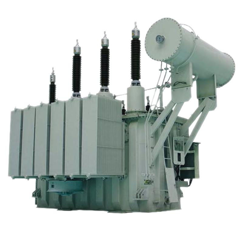



 110kV 115kV Power Transformer