 zishengelectric




Project Partners
Phone/WhatsApp: 8619131285373
Email: info@zishengtransformer.com
Factory Headquarters: No. 118, Jingyi Street, Economic Development Zone.
Search productSearch post
Project Partners
Phone/WhatsApp: 8619131285373
Email: info@zishengtransformer.com
Factory Headquarters: No. 118, Jingyi Street, Economic Development Zone.
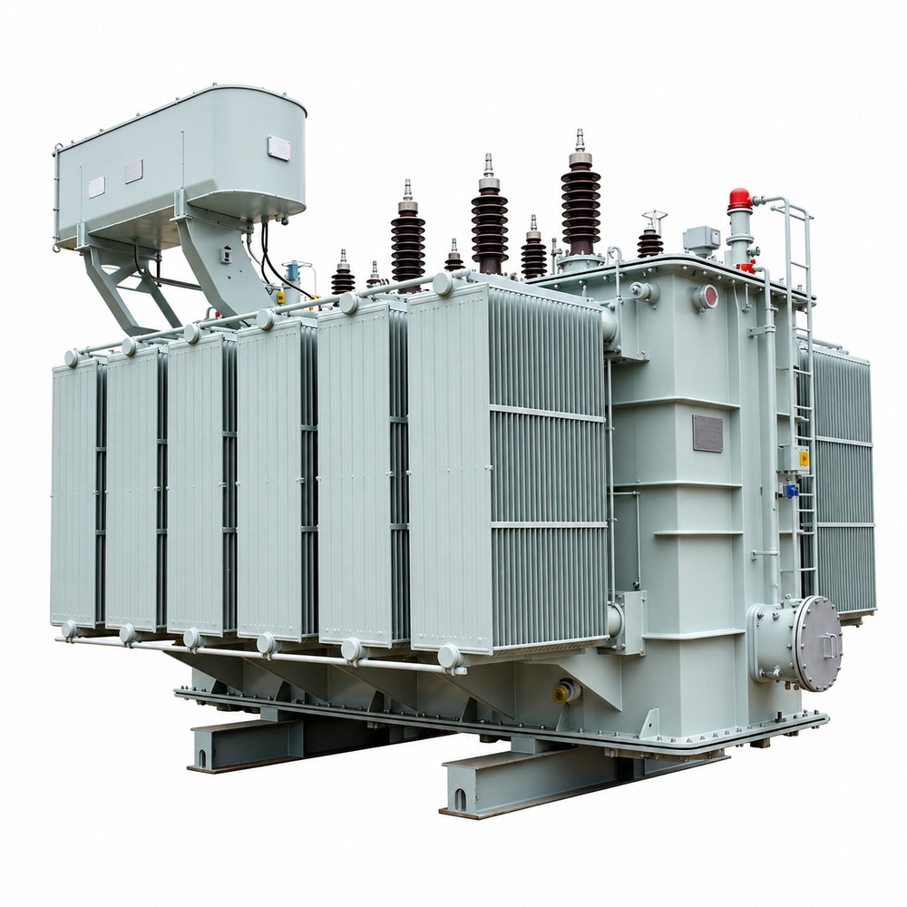
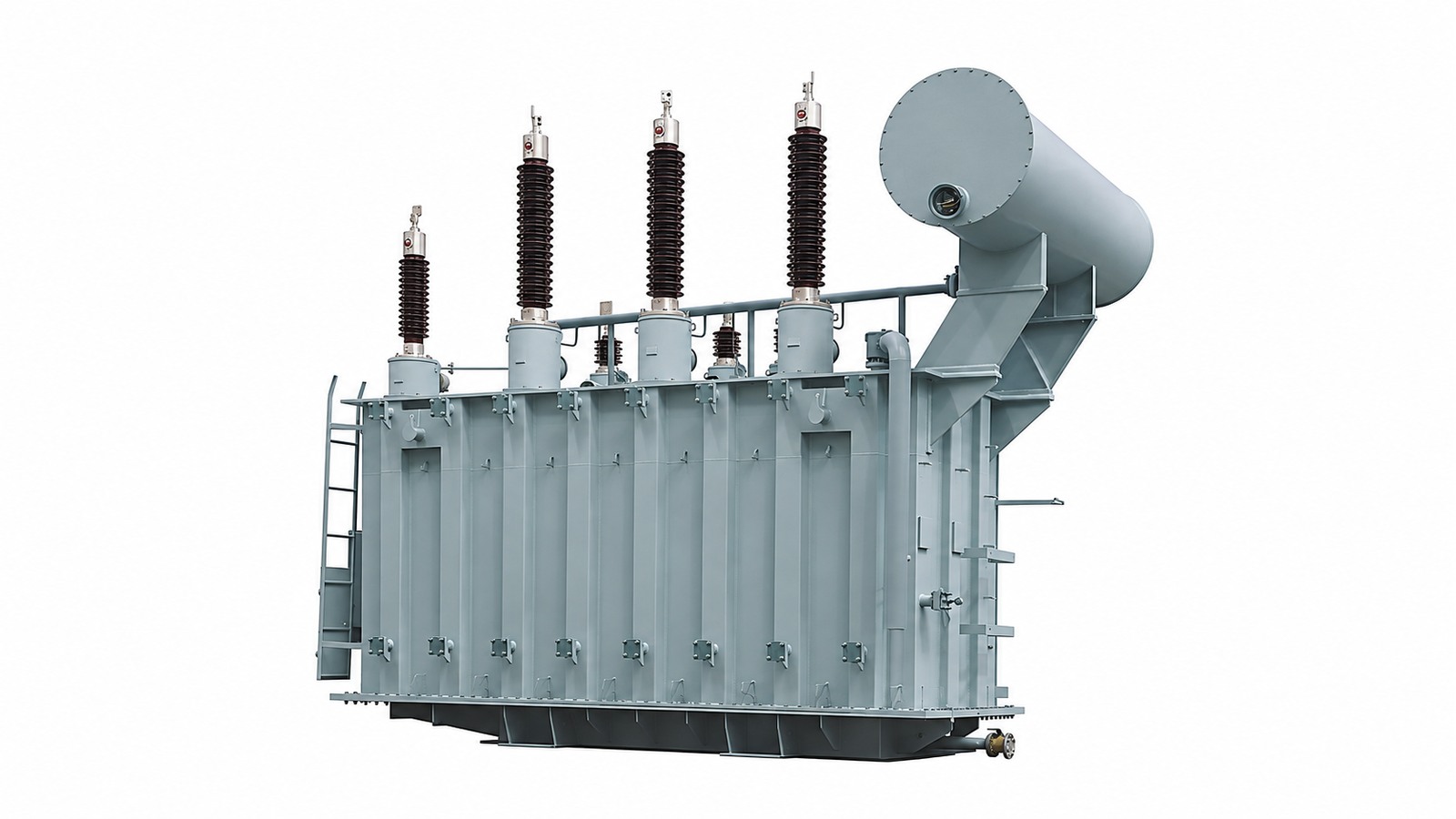
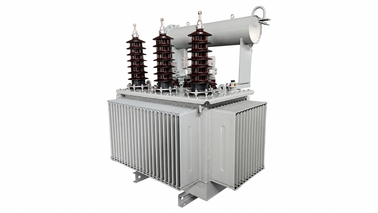
ZISHENG 35kV–46kV Power Transformers are designed for reliable voltage transformation in power transmission, distribution, industrial, mining, renewable energy, and utility applications. The transformers can be engineered according to project requirements, including capacity, voltage level, cooling method, insulation level, winding material, tap-changing system, and protection configuration.
The 35kV–46kV Power Transformer uses optimized core and winding designs to reduce no-load and load losses while maintaining stable operation under demanding electrical conditions. High-quality insulating materials and a robust tank structure provide reliable insulation and mechanical protection.
The transformer can be customized for different grid voltage levels, power capacities, environmental conditions, installation methods, and project standards. This makes it suitable for medium- and high-voltage substations, industrial power systems, renewable energy projects, and utility distribution networks.
ZISHENG applies process control from raw-material selection and component manufacturing through assembly and final testing. Each transformer is subject to performance and electrical tests before shipment to ensure compliance with the agreed technical specifications.
All technical parameters can be customized according to the project requirements, including:
The technical data above is for reference only. ZISHENG provides project-specific transformer designs based on the customer's grid conditions, installation environment, operating requirements, and applicable standards.
Select the final equipment from an approved data sheet and accessory schedule. An OLTC, nitrogen blanket, cooling fans, additional monitoring or other listed configuration is included only when specified in the order. The nominal voltage does not make every capacity, secondary voltage and accessory combination interchangeable.
Use the following existing technical data as catalogue references pending confirmation of the offered unit. The published overview range is 300–100,000 kVA, while the main specification table below states 1,000–63,000 kVA; the custom section refers to 1 MVA–63 MVA+. These ranges need engineering reconciliation before a final offer is issued.
| Item | Technical Specification |
|---|---|
| Product Type | Oil-Immersed Power Transformer |
| Rated Capacity | 1,000–63,000 kVA |
| Rated Frequency | 50 / 60 Hz |
| Number of Phases | 3 Phase |
| Installation | Outdoor / Indoor |
| Cooling Method | ONAN / ONAF |
| Insulation Medium | Transformer Oil |
| Core Material | High-permeability Grain-Oriented Silicon Steel |
| Winding Material | Copper / Aluminum |
| HV Rated Voltage | 35 kV / 38.5 kV / 40.5 kV / 46 kV |
| LV Rated Voltage | 0.4 kV / 6.3 kV / 10.5 kV / 11 kV / 13.8 kV |
| Tap Range | ±2 × 2.5% / ±5% / Customized |
| Tap Changer | Off-Circuit Tap Changer / OLTC |
| Vector Group | Dyn11 / YNd11 / Customized |
| Neutral | Neutral Bushing Available |
| Impedance Voltage | Typically 6–12% / Customized |
| No-Load Loss | According to IEC / Project Requirements |
| Load Loss | According to IEC / Project Requirements |
| Temperature Rise | According to IEC 60076 |
| Noise Level | According to IEC / Project Requirements |
| Service Life | ≥30 Years under Normal Operating Conditions |
| Applicable Standard | IEC 60076 / IEEE C57 / ANSI / Customer Specification |
| Item | Specification |
|---|---|
| Rated Voltage | 35 kV / 46 kV |
| Maximum System Voltage | Project Dependent |
| Power Frequency Withstand | According to Insulation Class |
| Lightning Impulse Withstand | According to IEC 60076 / Project Requirements |
| Partial Discharge | According to Applicable Standard |
| Short-Circuit Withstand | According to IEC 60076 |
| Insulation Class | Oil-Immersed |
| Frequency | 50 / 60 Hz |
| Phase Sequence | ABC |
| Polarity | According to Vector Group |
| Voltage Regulation | Project Dependent |
| Efficiency | ≥98% depending on capacity and design |
| Power Factor | Project / Grid Dependent |
High-Voltage Winding
Low-Voltage Winding
| Item | Specification |
|---|---|
| Insulating Oil | Mineral Oil / Natural Ester / Customized |
| Main Insulation | Oil-Paper Insulation System |
| Insulation Structure | High-Voltage / Low-Voltage / Core Insulation |
| Drying Process | Vacuum Drying |
| Oil Treatment | Vacuum Oil Filtration |
| Insulation Level | Project Specific |
| Partial Discharge | Controlled according to applicable standard |
Depending on transformer capacity:
ONAN — Oil Natural Air Natural
ONAF — Oil Natural Air Forced
Optional:
Off-Circuit Tap Changer
Typical configuration:
On-Load Tap Changer — OLTC
Available for applications requiring voltage regulation under load.
Optional features:
Depending on transformer design and capacity:
Optional monitoring and protection systems include:
The adopted standard and approved inspection and test plan determine the required factory test scope. The lists below identify test and inspection topics for review, rather than an identical mandatory package for every transformer.
Routine Electrical Tests and Additional Agreed Checks
Other Tests — Classification Depends on the Adopted Standard
According to project requirements:
Primary Standard
Depending on the target market, the transformer can also be designed according to:
35kV / 46kV power transformers are suitable for:
The original introduction lists a basic impulse insulation level (BIL) of 200–650 kV and a typical impedance of 8–12%. These published references require engineering confirmation for the actual winding voltage, highest voltage for equipment, insulation coordination and rating; they are not universal guaranteed values for all 35 kV / 46 kV designs.
Other existing configuration references include secondary voltages of 6.6 kV, 11 kV, 13.8 kV and 33 kV; 13.8 kV / 480 V and 35 kV / 11 kV examples; off-circuit taps of ±2 × 2.5% or ±5%; and ANSI 61 gray. Confirm the applicable configuration, rather than combining every listed option into one unit.
Existing references to efficiency ≥98% and service life ≥30 years require a defined rating, loading point, power factor, operating conditions and contractual guarantee basis. They are not unconditional guarantees. The accessory list is a selection schedule. The applicable standard and order determine whether a particular impulse, partial-discharge or other test is routine, type or special; do not apply one classification to every unit.
Send the single-line diagram, load schedule and site design basis with the enquiry. The product name alone does not establish capacity, insulation level or compatibility with an existing parallel transformer.
| Purchaser input | Engineering decision |
|---|---|
| Rated MVA and load profile | Continuous loading, motor starting, cyclic peaks, harmonic losses and future expansion; state ratings separately for each cooling stage. |
| HV / LV voltage and frequency | Nominal voltages, highest voltage for equipment, phase number, system grounding and operating range. |
| Vector group and impedance | Neutral availability, phase displacement, fault duty, protection coordination and any parallel-operation limits. |
| Tap-changing requirements | Off-circuit or on-load duty, regulation range, number of positions, local/remote control and auxiliary supply. |
| Site conditions | Ambient temperature, altitude, pollution, corrosion, seismic requirements, sound limits and indoor/outdoor installation. |
| Civil and electrical interfaces | Foundation loads, rail spacing, oil containment, fire separation, cable approach and maintenance access. |
| Delivery and documents | Transport envelope, lifting access, Incoterm, required inspection points, test reports, approved drawings and spare parts. |
Select an off-circuit tap changer only where adjustment can be made with the transformer isolated, de-energized and safely earthed. Specify an on-load tap changer (OLTC) when regulation under load is required; the OLTC, drive, controller and protection interfaces must be defined together.
Our 35kV / 46kV Power Transformers can be engineered and manufactured according to specific grid conditions, project requirements and applicable international standards.
| Customization Item | Available Options |
|---|---|
| Rated Capacity | 1 MVA – 63 MVA+ |
| High Voltage | 35 kV / 38.5 kV / 40.5 kV / 46 kV |
| Low Voltage | 0.4 kV / 6.3 kV / 10.5 kV / 11 kV / 13.8 kV / Customized |
| Frequency | 50 Hz / 60 Hz |
| Phase | Three Phase |
| Voltage Ratio | Customized according to project requirements |
| Impedance Voltage | Customized |
| No-Load Loss | Optimized according to efficiency requirements |
| Load Loss | Optimized according to project requirements |
| Insulation Level | Customized according to system voltage and applicable standards |
| Lightning Impulse Level | Customized |
| Short-Circuit Withstand | Designed according to IEC / IEEE requirements |
Off-Circuit Tap Changer
On-Load Tap Changer — OLTC
Customers can select the cooling configuration according to transformer capacity and operating conditions:
| Item | Customization |
|---|---|
| Transformer Oil | Mineral Oil / Natural Ester / Customized |
| Insulation System | Oil-Paper Insulation |
| Insulation Level | Project Specific |
| Insulation Coordination | Customized |
| Partial Discharge Requirement | Project Specific |
| Vacuum Drying | Available |
| Oil Treatment | Vacuum Filtration / Degassing |
| Sealing System | Conventional / Fully Sealed |
The transformer tank can be customized according to transportation, installation and environmental requirements.
Available configurations include:
Optional protection and monitoring systems:
The transformer can be engineered for different operating environments:
Hot & Humid Areas
Desert Areas
Coastal / Marine Areas
High-Altitude Areas
Cold Climate
Optional surface-treatment systems:
The transformer can be manufactured according to:
Customized documentation can include:
For EPC and utility projects, we can customize the transformer based on:
Grid Requirements → Electrical Parameters → Insulation Level → Cooling → Protection → Environmental Conditions → Applicable Standards → Transportation → Installation
Engineered to Your Project. Manufactured to Your Specification.
The approved offer should identify the selected winding material, cooling ratings, tap changer, insulating fluid, termination arrangement, alarm/trip contacts and auxiliary supply. Resolve departures from the purchaser specification before releasing drawings for manufacture.
Plan shipment from the approved transport drawing, shipping mass and route limits. A complete transformer in this voltage class may require a suitable flatbed, low-bed or other engineered transport arrangement; neither a small timber pallet nor a standard container is a universal solution.
The manufacturer determines whether the main tank travels assembled, partly dismantled, oil-filled or under an approved dry-gas preservation procedure. Protect sealed openings and record the transport oil level or gas condition. Remove bushings, radiators, conservator and other accessories only where required by the approved shipping design and reassembly instructions.
Pack detached accessories in numbered, suitably braced wooden crates or other specified protective packages. Protect porcelain, instrument faces, machined flanges, gasket surfaces and control equipment against impact and moisture. Use treated and marked solid-wood packaging where the destination requires it. Match every package to the packing list and assembly drawings.
Use only designated lifting and jacking points and the approved rigging plan. Tank lifting points, active-part lifting points and accessory lifting points are not interchangeable. Confirm crane capacity at the actual operating radius, sling geometry, ground bearing capacity and the unloading route. Never attach restraints to bushings, radiators or fragile pipework.
At arrival, photograph the shipment before unloading; compare package numbers, seal condition, visible damage, oil leakage and the specified oil level or gas condition with dispatch records. Review any fitted transport recorder and log missing parts or abnormal indications. Quarantine damaged equipment for technical review before assembly or energization. Follow the approved oil handling, reassembly and site testing procedure.
The inspection and test plan should identify material records, winding and insulation checks, core-and-coil assembly, lead connections, active-part drying, tank cleanliness, oil processing, leak checks and final accessory inspection. Record applicable inspection points against the order and transformer serial number.
Agree the inspection and test plan before manufacture, including hold/witness points, notice periods, the adopted standard and acceptance criteria. Customer or independent inspection attendance covers the agreed scope and does not establish an unqualified certification claim.
Trace material and process records to the order and the finished transformer serial number. The release dossier should identify approved drawings, the final data sheet, routine test results, specified additional evidence, accessory checks, deviations and their closure.
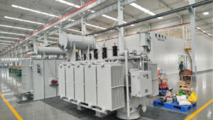
Routine electrical tests verify the completed transformer against the governing standard and approved data sheet. The precise test list, methods, tolerances and report format must be agreed before manufacture. Process inspections, routine tests and additional design verification serve different purposes.
| Verification group | Purpose and scope |
|---|---|
| Manufacturing and final inspection | Check workmanship, identification, dimensions, oil system, coatings, accessories and wiring against approved drawings and procedures. |
| Routine electrical tests | Typically include winding resistance, voltage ratio and phase displacement, no-load loss and current, load loss and impedance, plus applicable routine dielectric tests. The adopted standard determines the required list and acceptance criteria. |
| Other specified tests | Temperature-rise verification, lightning impulse, partial discharge, sound, short-circuit withstand evidence and frequency-response measurements depend on the applicable standard, rating, design and contract. Classification as routine, type or special is not identical for every order. |
| Witness FAT | A purchaser or appointed inspector witnesses agreed hold points, reviews results and closes deviations. FAT is an acceptance arrangement, not a separate universal test standard. |
Request a serial-number-linked routine test report, approved data sheet, final outline and terminal drawings, wiring diagrams, accessory settings, applicable oil records, packing list and installation/operation manual. Identify additional test reports or design evidence specifically required by the contract. Record calibration references, test connections, tap positions and relevant temperatures so results remain traceable.
Use the contractually specified editions of the IEC 60076 series or applicable IEEE C57 standards. A technical standard defines requirements and test methods; mentioning it does not establish independent product certification.
For site commissioning interfaces, use the transformer site acceptance and pre-energization checklist. Site checks address transport, reassembly, connections and protection proving in addition to the factory baseline.
Step down the incoming network to a defined medium-voltage bus for utility feeders, water supply, transport infrastructure or regional distribution. Select voltage ratio, neutral arrangement and fault duty from the utility connection requirements; use downstream transformers where low-voltage station services are needed.
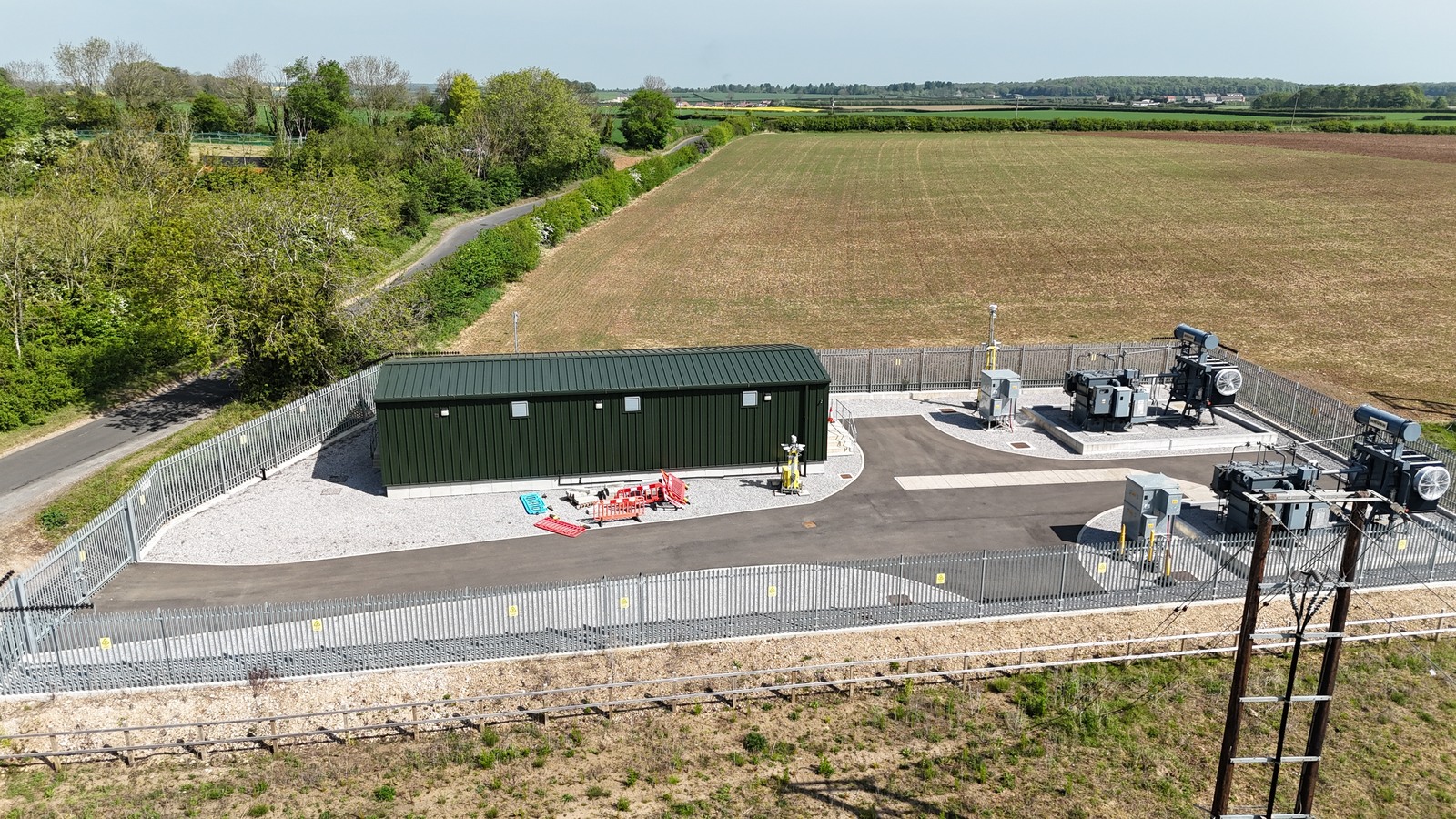
Supply a defined production area, mine surface distribution or process installation. Motor starting, drive harmonics, dusty or corrosive surroundings and maintenance access can affect the winding, cooling, enclosure and accessory specification. Verify suitability for the actual load and environment before ordering.
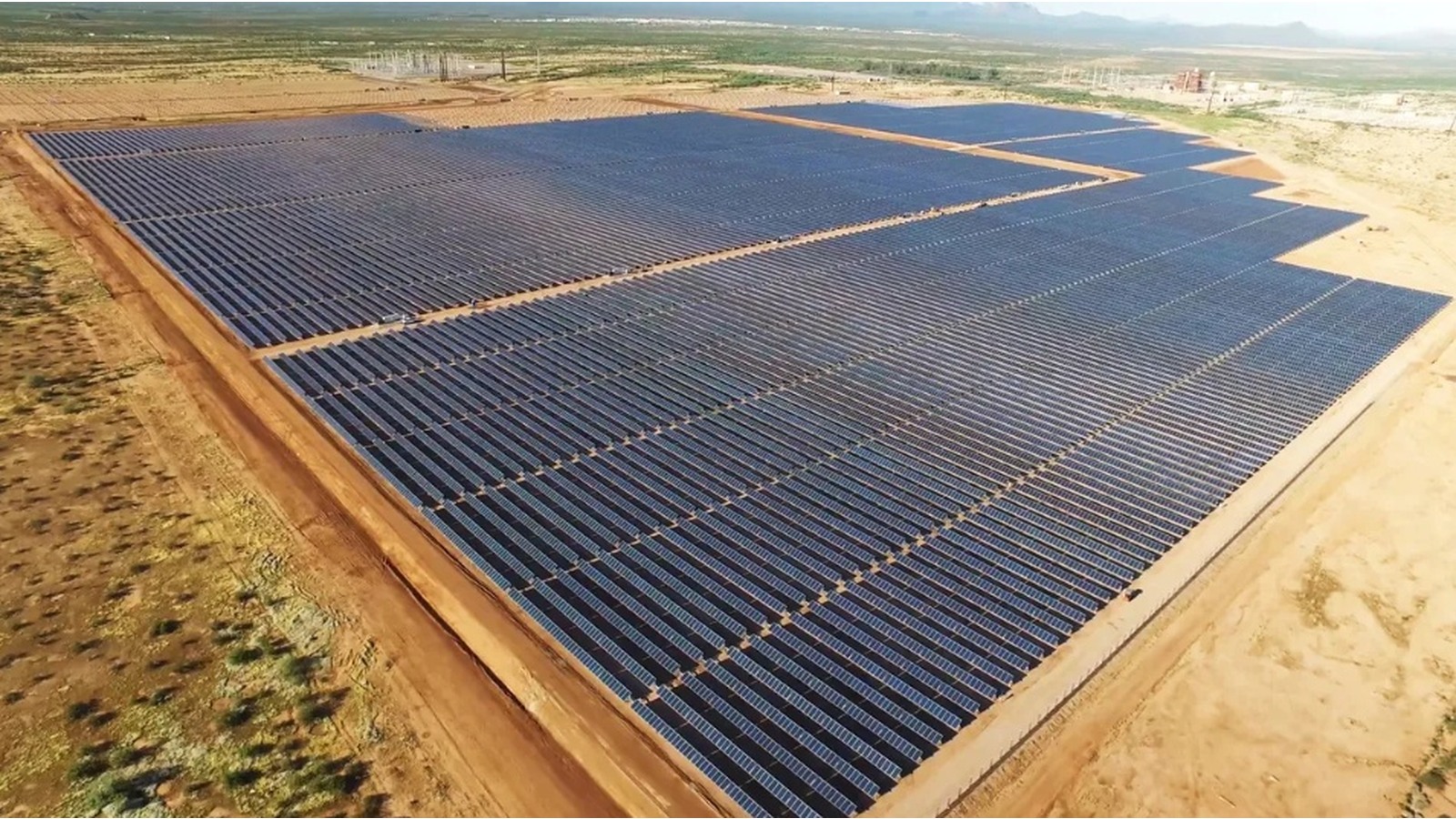
Connect a defined generation block or collection system where the required transformer voltages fall within the confirmed design. State power-flow direction, inverter harmonics, earthing, reactive-power duty, switching conditions and grid-code requirements.
A utility intake supplying a pumping network requires a three-phase 35 kV / 10 kV transformer to serve medium-voltage motor feeders and downstream auxiliary transformers. The load schedule separates running pumps, standby pumps, starting sequences and station services. Standby motor nameplates are not simply added to the simultaneous operating load.
| Engineering item | Case requirement |
|---|---|
| Voltage and duty | 35 kV / 10 kV, three-phase; frequency and utility insulation requirements stated in the project data sheet. |
| Capacity selection | Use coincident running demand, power factor, the largest permitted motor start and the agreed contingency. Confirm MVA and cooling stages after the load study. |
| Site constraint | Arrange radiator access, cable entry, oil containment and lifting space within the substation compound. Coordinate the transformer foundation and underground services before delivery. |
| Configuration | Select ONAN or ONAN/ONAF duty, approved vector group, neutral treatment and tap-changing method to match feeder regulation and protection. |
| Engineering check | Assess voltage dip during pump starting and the allowable short-circuit level at the 10 kV bus. Confirm bus-section interlocks and any parallel-operation requirements. |
| Acceptance | Review the approved data sheet and serial-number-linked test report; verify phase identification, winding connections, ratio/tap position, protection trips and arrival condition before energization. |
The procurement package should include the utility voltage envelope, pump starting method and sequence, protection study, transformer outline, cable interface drawing and witness inspection schedule. This gives the purchaser a common basis for comparing offers and resolving the motor-starting and civil interfaces.
A process-plant intake uses a three-phase 46 kV / 13.8 kV transformer to supply a defined production area through a medium-voltage distribution board. Large motors, drives and auxiliary transformers create different loading conditions during start-up, normal production and a planned restart. The transformer rating is assigned to the connected process area rather than inferred from the size of the entire facility.
| Engineering item | Case requirement |
|---|---|
| Voltage and load | 46 kV / 13.8 kV, three-phase; assess continuous motor demand, variable-speed drives and auxiliary loads together. |
| Capacity and thermal basis | Confirm diversified kVA, harmonic spectrum, ambient conditions and each cooling-stage rating. Apply any expansion allowance transparently in the approved load schedule. |
| Installation constraint | Coordinate transformer position, cable bend radius, fire separation, oil drainage and replacement access around operating plant equipment. |
| Regulation and protection | Assess whether off-circuit taps are sufficient or an OLTC is required. Coordinate differential protection, neutral grounding, CT interfaces and feeder relay settings. |
| Key engineering issue | Review starting voltage dip, fault current, harmonic heating and switching sequences. Parallel operation requires compatible ratio, tap position, phase displacement and impedance characteristics. |
| Acceptance and handover | Agree FAT witness points, wiring checks, final drawings, oil records, transport inspection and site protection proving before release for energization. |
For a brownfield installation, the equipment order should state outage windows, temporary supply responsibilities and the permitted assembly area. Shipping dimensions and lifting loads need to be checked against the actual access road, crane position and foundation, rather than left until dispatch.
It connects a 35 kV or 46 kV network to the project distribution voltage for utility, industrial, infrastructure or generation service. The ordered unit has a defined voltage ratio, MVA rating and phase connection; it does not automatically switch between both primary voltages.
Existing published examples include 35 kV / 10 kV and 46 kV / 13.8 kV. The page also lists 35 kV / 0.4 kV and 13.8 kV / 480 V configurations for separate engineering review; these do not establish a universal combination at every capacity. Confirm the actual ratio, insulation level, tap range and terminal current in the approved offer. A dual-voltage winding requires a purpose-designed connection arrangement.
Use coincident demand, load power factor, motor starting, harmonic content, ambient conditions, contingency and future load. Compare bidders at the same cooling-stage rating and loss-evaluation basis. Confirm the applicable capacity range with engineering before purchase.
ONAN uses natural oil and air circulation. ONAF adds forced air from fans. The nameplate must state the approved MVA for each stage. ODAF or other forced-oil cooling is a separately confirmed design option.
Copper or aluminum windings and mineral oil or a specified ester fluid may be considered. FR3 is a branded natural ester. Material, fluid, temperature-rise basis, seal compatibility and the required test evidence must be confirmed for the ordered design.
No single accessory list applies to every order. Specify off-circuit or on-load tap changing in the contract. A Buchholz relay requires a suitable conservator pipe arrangement. Online monitoring, current transformers, cooling controls and remote contacts follow the approved accessory schedule.
Agree routine tests under the adopted standard and the order-specific inspection and test plan. Additional dielectric, thermal, sound or mechanical verification depends on the standard, rating, design and contract. A witness FAT can be arranged around agreed hold points. Obtain serial-number-linked reports and final drawings; no test result or pass rate is stated on this page.
Use the approved transport drawing, packing list, preservation plan and lifting instructions. The main tank may travel assembled or partly dismantled as specified; loose accessories require separate protection. Record shipment condition, leakage, missing parts and any transport-recorder indications before unloading and assembly.
Specify the applicable parts and editions of IEC 60076 or IEEE C57, together with utility and project requirements. Identify the guaranteed values, tolerances, test classification and document requirements. A standards reference is not a product certification.
The existing page references 25–30 years or more, but this is not a guaranteed life or warranty. Insulation temperature, moisture, oxygen, loading, through-fault exposure and maintenance affect ageing. Confirm the contractual design basis and follow the operation, inspection and oil-monitoring instructions.
The existing catalogue lists 1.6, 2.5, 5, 6.3, 10, 12.5, 16, 20, 25, 31.5, 40, 50 and 63 MVA as common references. Availability and the applicable overall range need confirmation against the chosen voltage ratio and design. Do not treat the list as a stocked inventory.
Supply both units’ nameplate and test data. Compare ratio and tap positions, phase sequence, vector group, impedance and impedance angle, ratings, neutral arrangements and the intended load-sharing scheme. A matching nominal voltage alone is insufficient.
Provide the single-line diagram, load and motor-starting data, utility requirements, site design basis, transport limits, technical specification, document schedule and inspection requirements. Define the approval responsibilities for civil, cable, protection and control interfaces.
For a defined 35 kV substation rating, review the 31500kVA 35kV oil-immersed copper transformer and compare its confirmed data sheet with the project requirements.
For delivery and commissioning coordination, read the transformer site acceptance test checklist for EPC projects.
35kV 46kV Power Transformer