 zishengelectric



news
News Center
Providing high-quality power to the world
Search productSearch post
news
Providing high-quality power to the world
Substation HMI mimic acceptance checks whether the operator’s graphical view represents the installed equipment, its actual indications and the quality of the underlying information. A neat single-line screen can still contain a wrong bay label, a reversed status or a value that looks current after communications have failed. Those errors need to be found before the screen becomes part of routine operation.
For EPC handover, the useful outcome is a traceable set of display checks tied to the approved drawings and signal list. This guide focuses on the mimic and its information behavior. It does not provide switching instructions or replace separate protection, interlocking and command-path acceptance.
Collect the approved single-line diagram, equipment-tag register, signal list, display conventions and HMI screen schedule. Identify the revisions implemented by the integrator. A screenshot cannot be accepted against an informal drawing that differs from the installed station. The first check is whether the display, design documents and physical equipment describe the same arrangement.
Define the screens included in the package: station overview, bay details, transformer overview, auxiliary systems and any related alarm or measurement views. Record navigation between them. The owner should be able to move from a general indication to the correct equipment detail without relying on an integrator’s explanation of hidden naming conventions.
SEL’s SCADA and HMI service description identifies communication status, power-system data and alarm management as distinct HMI functions. That distinction helps frame acceptance: a correct diagram is only one part of the operator interface, and each associated information function needs a defined scope.
An accepted mimic is not permission to energize equipment or operate a breaker. The project must retain its approved commissioning and operating controls. During display verification, use authorized simulation or test methods and make the test boundary explicit. Do not click a live command merely to see whether a symbol changes.
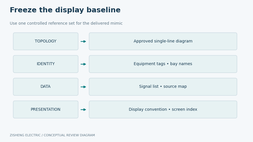
Compare the screen with the approved electrical arrangement. Check bus sections, transformer connections, feeder names and equipment identifiers. Verify that the arrangement is understandable at the normal workstation scale. A correct signal attached to the wrong bay symbol can be more misleading than a visibly missing signal.
Use physical equipment tags as the common reference. Where the HMI uses a short label, document how it relates to the full asset identifier. Confirm that duplicated names are resolved across voltage levels and station areas. Operators should not need to infer which transformer is meant from the position of a small icon.
Review screen variants and operating configurations included in the scope. A display copied from another project may retain an unused bus connection, spare feeder label or obsolete device. Remove or clearly identify items according to the approved design. An apparently harmless leftover symbol can mislead later troubleshooting.
Create a display-point map connecting each dynamic object to its source signal, address or tag, displayed text, symbol behavior and applicable quality information. The technical implementation may vary by system, but the acceptance record should expose the relationship clearly enough for a reviewer to trace it.
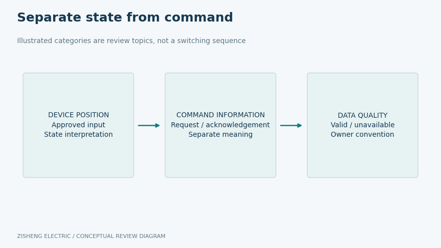
For switching-device indications, include the states required by the approved design. These may involve open, closed, intermediate, discrepant or invalid conditions, depending on the device and signal arrangement. Do not invent a universal truth table. Obtain the approved interpretation of the actual inputs and verify that the HMI follows it.
Color alone should not carry the entire meaning. Apply the owner’s approved combination of labels, symbols, legends and other cues so that different conditions remain distinguishable. Test the result at the actual display size, including common navigation views. A legend hidden on a separate engineering screen may not help an operator interpret an unexpected indication.
A command request, a command acknowledgement and a device-position indication are different events. If the HMI displays them, document which information drives each part of the screen. A successful request should not be presented as proof that the physical device reached the intended position. Command-path verification remains a separate, controlled activity.
| Display claim | Verification evidence | Typical discrepancy |
|---|---|---|
| Correct equipment identity | Screen object matched to approved tag and drawing | Copied label points to another bay |
| Correct state indication | Authorized source stimulus and observed symbol state | Open and closed interpretation reversed |
| Trustworthy data quality | Approved invalid or stale-data case and visible response | Old value remains apparently healthy |
| Correct measurements | Source quantity, units, scaling and sign checked | Wrong multiplier or power-flow convention |
| Usable navigation | Overview, detail and alarm destinations checked | Link opens a similar but incorrect bay |
| Controlled final version | Accepted screen build and configuration index | Site runs a different revision from the test record |
Record the actual result for each checked object or agreed group. If a representative sample is accepted, explain why it represents the remaining objects and identify the untested coverage. Copying a successful result across all bays can conceal a single mapping error introduced during configuration.
Check the units, scaling, decimal presentation and sign convention of each relevant measurement. The source and screen should agree about whether a quantity is phase-related, line-related, total, instantaneous or accumulated. A plausible number is weak evidence when its meaning is unclear.
Power-flow direction deserves particular attention at transformer and bus interfaces. Use the project’s agreed reference direction, and make labels consistent between the overview, detailed screen and exported data. Review how negative values are displayed where they are valid. Do not force an expected positive value by changing a sign without engineering approval.
For transformer accessories, verify tap position, temperature names and any calculated or selected values in the agreed scope. Distinguish a direct measurement from a calculated value or a maximum selected from several channels. The label should tell the operator what is being displayed without promising information that the source does not provide.
The acceptance plan should define the required display behavior when updates stop or data become invalid. Numerical response criteria must come from the approved system requirements. A generic expectation such as fast enough is difficult to test, while an arbitrary delay copied from another project may be inappropriate for the installed architecture.
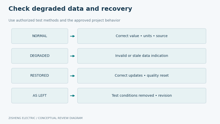
Normal operation is only one display condition. Agree controlled cases for unavailable source data, a communication interruption or another relevant quality change. Observe the affected object and any operator notification. The display should behave according to the approved design and should not silently present old information as a fresh, valid state.
Keep the test boundary clear. Simulating a quality flag at the HMI input proves that display response; it does not demonstrate the whole path from a field device through every gateway. If the project requires end-to-end verification, the test method must cover that wider path under its authorized procedure.
Also verify restoration. Record whether the correct source values return, the quality indication clears appropriately and associated notifications behave as specified. An integrator’s temporary test value must not remain active after the session. Preserve the final accepted configuration and the record confirming removal of test conditions.
Walk through common information tasks with the owner’s operations representative: identify a transformer, open its detail view, find the associated alarm and return to the station overview. This is a usability check, not an operating drill involving live commands. Record confusing labels or navigation destinations while they are still easy to correct.
Check whether alarms and symbols use consistent equipment names. Where a detail window shows information from several devices, identify the source of each group. Avoid screens that imply a single healthy state when one contributing source is unavailable. Any summary status needs an approved definition and a traceable relationship to its inputs.
SEL’s Diagram Builder overview describes configurable power-system objects and alarm-screen tools. Such software capabilities do not guarantee the correctness of a particular project screen. The integrator still needs to demonstrate the chosen object behavior, mapping and presentation in the delivered configuration.
Give each discrepancy a screen reference, equipment tag, expected behavior, actual behavior and supporting evidence. This makes it possible to distinguish a display-label correction from a source-mapping or logic change. Different changes can affect different parts of the system and need different review and retest scopes.
When a shared template is corrected, identify every screen that uses it. A fix for one bay may alter several others. Conversely, a local correction may leave the same defect elsewhere. The integrator should state the change scope, and the acceptance authority should agree what must be verified again before closure.
Freeze the final screen build, signal configuration and relevant software versions in the handover index. Retain readable exports or screenshots where useful, together with the controlled backup location. Do not place credentials in ordinary test records. The owner’s access process should manage secrets separately from the engineering evidence.
Before closing the review, choose a case that is easy to misinterpret: two similarly named bays, a negative power value, or an unavailable source with a retained last value. The case should come from the actual design and be applied through an authorized test method. Ask the operations representative to explain what the screen means without prompting from the integrator.
If the explanation differs from the approved meaning, investigate the label, legend, navigation and data-quality presentation. The problem may be interpretation rather than a faulty source signal. Record the agreed correction and verify it at the workstation scale used in service. A display that looks clear on an engineering laptop may be less clear on the installed screen.
Retain this check as part of the acceptance record rather than treating it as informal training. It gives the owner evidence that the delivered presentation supports the intended task, while leaving operational decisions within the approved operating procedures.
The transformer SCADA point-to-point test guide addresses source-to-destination signal identity. Mimic acceptance adds the operator-facing interpretation of those signals. Keep the records linked so that the reviewer can distinguish a correctly delivered point from a correctly presented meaning.
The custom engineering interface review can coordinate transformer accessory information with the control-system package. Equipment discussions may reference the 110 kV–115 kV power transformer and 10 kV distribution transformer. HMI functions belong to the agreed project scope and are not automatic features of every transformer offer.
Provide the accepted screen index, display conventions, source-point map, checked-state records, measurement definitions, discrepancy closures and final configuration references. Include the limitations of any representative testing and the remaining actions accepted by the owner. Training should use the delivered screens and actual equipment names.
Send the single-line diagram, equipment tags, signal list, HMI screen schedule, owner display conventions and commissioning boundaries. Identify the transformer accessory data and control-system parties involved. Substation HMI mimic acceptance is complete when the operator can identify the correct equipment, understand the displayed state and recognize untrustworthy information. Zisheng Electric can review the transformer-side signal scope as part of the agreed EPC package.

Build a transformer SFRA baseline package for EPC handover: align test configurations, preserve raw files and resolve comparison gaps before release.
View details
Plan a transformer turns-ratio field test with a tap-by-tap matrix, verified nameplate basis, phase connections, safety boundary and a clear disposition path for unexpected readings.
View details
A commissioning-focused guide to transformer CT secondary circuit handover: core identity, terminal mapping, shorting facilities, polarity records, test boundaries and controlled release to protection systems.
View details
Plan substation special tools handover: verify equipment compatibility, torque adapters, tool records, storage and owner acceptance before EPC demobilization.
View details