 zishengelectric



news
News Center
Providing high-quality power to the world
Search productSearch post
news
Providing high-quality power to the world
Zisheng Electric works with EPC teams that have to make transformer and substation equipment fit the same electrical and physical design. A substation surge arrester interface often looks like a small accessory on a general arrangement drawing. In service, its selection, location and connection path affect the protection seen at a transformer terminal. The useful question is not simply whether an arrester appears on the bill of materials. It is whether its duty, insulation coordination, physical route and handover evidence have been agreed by the parties who design, supply and install the bay.
This guide sets out an EPC review sequence for gapless metal-oxide arresters on AC systems above 1 kV. It avoids universal voltage ratings or lead-length rules: those values belong to the actual system study, manufacturer data and owner specification. The workflow is relevant to transformer line terminals, cable transitions, GIS-to-transformer connections and packaged substation boundaries.
Start with the single-line diagram and the equipment arrangement. Identify every protected terminal and the surge paths reaching it: overhead line entry, cable transition, switchgear bus, transformer HV or MV bushing, and any neutral point requiring its own study. The line-side arrester shown on one drawing may protect a different asset than the transformer-side arrester on another. Assign an owner to each device, bracket, conductor, counter, earth link and associated drawing. Without that scope matrix, the electrical design can be complete on paper while the site team still lacks a support or a route to the earth grid.
Ask who approves the insulation-coordination study, who supplies the selected arrester data, and who verifies the as-installed lead geometry. Record whether the transformer supplier provides terminals or brackets, whether the switchgear contractor supplies the conductor, and whether the civil package reserves space and access. The transformer–GIS interface review illustrates why a compliant transformer and a compliant switchgear package can still leave a gap at their connection. Apply the same discipline to arrester interfaces.
A technical schedule should identify the system highest voltage, operating and fault-related temporary overvoltages, earthing method, prospective energy stresses, pollution environment and applicable insulation withstand levels. A layout schedule should identify the installation point, mounting orientation, clearances, terminal type, earth route, mechanical support and access for inspection. Both schedules must refer to the same tagged device. A catalogue family alone cannot close a project-specific duty review.
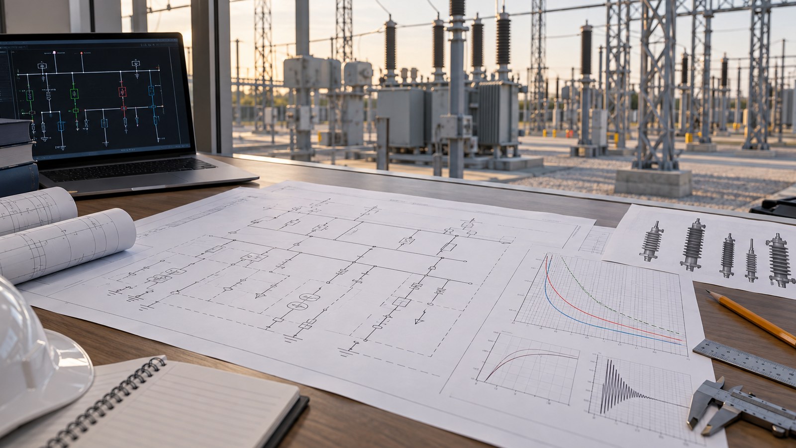
IEC 60099-4:2014 covers nonlinear metal-oxide resistor surge arresters without gaps designed to limit surges on AC power circuits above 1 kV. IEC 60099-5:2013 provides selection and application guidance, and IEC 60071-2:2023 deals with insulation-coordination application guidelines for three-phase AC systems. These documents support a disciplined study, but the EPC team still has to provide the network and equipment inputs. The edition and any owner amendments should be fixed in the procurement specification.
Compare the insulation withstand of the protected equipment with the arrester’s relevant protective characteristics under the surges considered in the study. Review power-frequency temporary overvoltage and its duration against the device’s capability, rather than choosing a lower rated voltage solely to obtain a lower residual voltage. Include switching duty, line or cable configuration and credible fault or reclosing cases where the study calls for them. The arrangement at a cable end may not be interchangeable with the arrangement at a transformer bushing: travelling waves, connection lengths and the distance between protection and equipment affect the voltage actually experienced at the terminal.
Do not copy a rating from a previous project based on nominal system voltage alone. Earthing practice and temporary overvoltage can change the duty materially. Conversely, a high arrester rating selected for comfort may reduce the protective margin. The electrical engineer should issue a traceable selection note with assumptions, manufacturer curves and the protected equipment withstand values. The transformer earthing interface guide
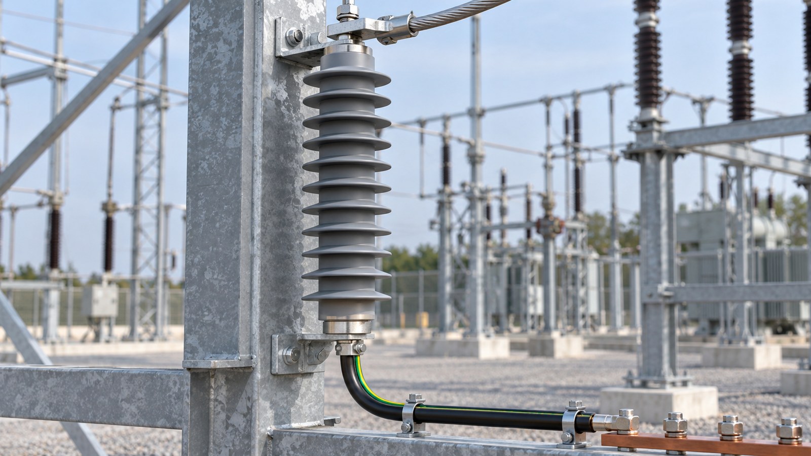
Show each phase device on a plan and elevation, with its phase terminal, earth terminal and the nearest protected equipment terminal. The protective performance at the asset includes the connection path, not only the value printed in an arrester catalogue. A long, looped or indirect connection adds inductive voltage during a fast surge. The study and supplier’s installation guidance should therefore inform placement and lead routing. Keep routes short and direct where the design permits, while respecting clearances, mechanical loads and maintainability. Do not impose a universal maximum distance without a project calculation.
Confirm whether the arrester is on a dedicated support, a transformer-mounted bracket or a bus structure. Check that the transformer terminal is designed for its conductor and mechanical forces; do not let a site installer improvise a cantilever load on a bushing. Allow for thermal movement, vibration, wind and conductor motion according to the project design. If a cable termination or GIS interface changes during detailed engineering, revisit the arrester location and leads. A drawing revision can quietly make the originally selected protection layout ineffective or impossible to install.
Make the earthing route explicit. The arrester ground lead, leakage-current monitor or discharge counter, isolation link and local earth-grid connection must form one reviewed arrangement. A monitor inserted in the lead must be compatible with the intended installation and accessible after energization. Ground-path continuity and bonding responsibility belong in the interface matrix. Separate protective-earthing checks from any diagnostic measurement that calls for an isolation link; the operating configuration must be restored and documented after testing.
| Decision item | Minimum project input | Release evidence and owner | Hold if unresolved |
|---|---|---|---|
| Electrical selection | System voltage, earthing, TOV, surge study, equipment withstand | Approved insulation-coordination note and arrester datasheet; system designer | Rating or protective margin relies on nominal voltage alone |
| Location | Single-line, plan, elevation, cable/GIS termination geometry | Tagged GA and lead-route drawing; electrical and mechanical leads | Device position and protected terminal do not match |
| Connections | Terminal details, conductor route, support loads and clearances | Approved interface drawing and supplier connection limits; package vendors | Site fabrication is needed to make the connection fit |
| Earthing and monitoring | Earth-grid detail, monitor/counter arrangement, test-link practice | Bonding drawing and inspection record; EPC installation lead | Return path or operating link state is ambiguous |
| Handover | Serial data, factory documents, installation instructions, inspection scope | As-built record, visual and continuity checks, open-item closure; commissioning lead | Acceptance is based only on a purchase order |
The table is a decision register, not a generic pass/fail standard. For each hold item, identify who can supply the missing evidence and whether the correction changes the electrical study, the drawing or both. Close the interface before cable dressing and bus installation make access difficult. For a compact package, confirm what is factory-installed and what must be completed on site; the boundary can differ from an open-air bay.
The arrester housing, creepage design, seals, terminals and support must suit the actual installation. Site inputs include pollution severity, salt exposure, dust, rain, humidity, ultraviolet exposure, altitude and ambient temperature. The responsible engineer should translate these into a project specification and verify the proposed manufacturer’s data. Avoid assuming that a product sold for outdoor use is automatically suitable for every coastal or industrial location. Confirm required clearances and the owner’s maintenance practices, including safe reach to counters and visual inspection points.
Shipping and storage deserve a line in the package plan. Arresters, monitors and fragile accessories may arrive separately from a transformer or prefabricated substation. Keep each item tagged to its bay and phase, preserve packaging according to supplier instructions, inspect for damage at receipt, and protect terminals from contamination until installation. A missing monitor or mounting adapter discovered at commissioning can delay an otherwise complete bay. Include spare-unit strategy, identification, compatible accessories and replacement procedure in the handover scope if the owner requires them.
Procurement comparisons should normalize the full installed interface, not just the arrester body price. Ask bidders for declared electrical characteristics, dimensional drawings, terminal arrangement, support loads, application limitations, routine/test documentation, installation instructions and accessory list. Specify what is included in the transformer package and what falls under the EPC contractor. Zisheng Electric’s substation auxiliary power interface discussion

At receipt and before installation, compare the nameplate and supplied documents with the approved schedule. Inspect the housing, terminals, seals, mounting parts and accessories for visible damage; record serial or batch identification where provided. After mounting, verify orientation, phase identity, clearances, conductor connections, earthing route, monitor/counter configuration and torque records in accordance with the approved method. Photograph the as-installed paths in a way that identifies the bay and device. Those records are far more useful than an unlabelled close-up when a later change is investigated.
Commissioning checks should be agreed with the manufacturer and project procedure. Do not apply a transformer or switchgear dielectric test across a connected arrester simply because the adjacent equipment has such a test; isolation and restoration requirements vary by test and device. Likewise, a leakage-current reading without operating voltage, temperature and the manufacturer’s method can be misleading. Document the test boundaries, temporary disconnects, restoration checks and witnesses. The EPC team should distinguish factory conformity evidence from site installation evidence and from the insulation-coordination design approval. None substitutes for the others.
At handover, provide the approved single-line and GA, selected arrester datasheet, study reference, inspection and test forms, terminal and grounding records, as-built photographs, open-punch closure, accessory instructions and maintenance/spares information. If the device is part of a transformer supply, align these with the transformer’s own manuals and terminal drawings. The high-voltage switchgear commissioning guide
A revised transformer bushing height, cable sealing end, GIS termination, support steel or earthing-grid detail should trigger an arrester-interface review. Mark the drawing revision and recheck the protection study assumptions if the electrical route or protected distance changes. A change notice should state whether the selected device remains valid, whether mechanical clearance is preserved and whether a new installation or test method is needed. The review can be short when the geometry is unchanged; it cannot be skipped because the component is inexpensive.
The same rule applies to late substitutions. A substitute arrester with a similar rated voltage may have different protective levels, TOV capability, dimensions, terminals or accessory compatibility. Obtain a side-by-side deviation record and the study owner’s disposition before approval. Prevent a purchasing equivalence from becoming an uncontrolled engineering change at site. Record spare compatibility by exact approved configuration rather than a broad catalogue description.
Zisheng Electric can review the transformer and substation equipment boundaries that determine where protection devices and their connections fit. Relevant product starting points include our 110 kV/115 kV power transformer and prefabricated substation ranges; final ratings and layouts always depend on the project’s engineering inputs. Send drawings, equipment datasheets, load lists, technical specifications, the single-line diagram, grid parameters, environmental conditions and installation-site conditions. Add the insulation-coordination study or its required inputs, transformer terminal drawings, bay GA, earth-grid details and owner utility requirements where available. Our engineering team will review the requirements and respond to project inquiries within 24 hours.
Technical references: IEC 60099-4:2014, IEC 60099-5:2013, and IEC 60071-2:2023. Confirm the contractually specified editions and access the full standards for detailed design.
Coordinate transformer condition monitoring for EPC projects: sensors, SCADA points, alarm ownership, communications, FAT, commissioning and data handover.
View details
Coordinate transformer fire protection for EPC projects: separation, oil containment, drainage, detection, suppression, control logic, FAT and site testing.
View details
Coordinate transformer protection interfaces for EPC projects, including CT inputs, mechanical trips, alarms, relay logic, SCADA, FAT and handover.
View details
In EPC projects, a transformer room must be designed as an operating space, not just a rectangle around the tank. Zisheng Electric engineers explain essential layout considerations including safety clearances, ventilation, lifting routes, and main...
View details