 zishengelectric



news
News Center
Providing high-quality power to the world
Search productSearch post
news
Providing high-quality power to the world
Substation time synchronization acceptance should demonstrate that the required devices use a trustworthy time reference and that the operator can recognize a loss of that trust. A clock showing the correct minute in the control room is not enough. Event records from protection relays, gateways and monitoring systems need an agreed time basis before they can support reliable investigation.
For EPC teams, this is an interface task involving the clock supplier, communications integrator, protection engineer, commissioning team and owner. The timing architecture may use several distribution methods and devices with different accuracy requirements. This guide defines the records and decisions needed to accept that architecture without assuming that every substation requires the same protocol or performance.
Start with an endpoint register. Identify each device that receives time, the function using it, the approved accuracy requirement, the distribution method and the evidence needed for acceptance. Separate ordinary supervisory event records from applications that depend on more demanding synchronization. The required performance comes from the system design and equipment application, not from a generic statement that the station is digital.
Mark the boundary of each test. A successful output check at a clock does not prove the time received by a relay at the end of the installed path. A workstation display can confirm presentation but may not reveal the accuracy or quality status used inside the source device. The test index should connect these distinct observations to the function being accepted.
Define whether records use UTC or local time, where any conversion occurs, and how daylight-saving settings are handled if applicable. Record the configuration of the clock, receiving devices, gateway, historian and workstation. Two correctly synchronized devices can appear to disagree when their exported records use different presentation conventions. Resolve that difference before treating it as a clock-performance defect.
Also distinguish a timestamp created at the source device from one added when a gateway receives a message. Network transfer and processing can separate those moments. The owner needs to know what a timestamp means before comparing it with another event. Display resolution, timestamp resolution and demonstrated synchronization accuracy should be recorded as separate concepts.
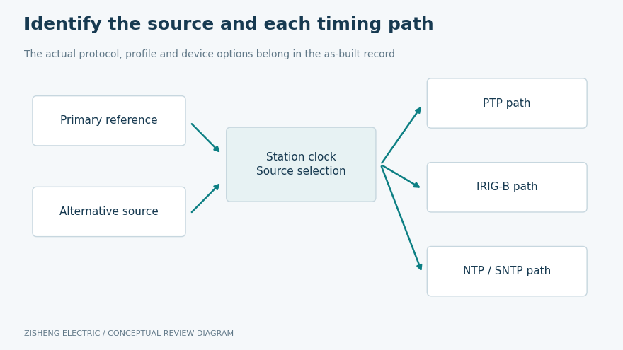
The as-built drawing should identify primary and alternative time sources, distribution equipment, relevant network paths and receiving endpoints. For satellite-referenced clocks, include the installed antenna and cable arrangement in the applicable inspection scope. For network-distributed timing, identify the relevant profile, domain and equipment functions as required by the approved design.
Manufacturer documentation shows why a protocol name alone is insufficient. The SEL-3400 description, for example, identifies demodulated IRIG-B distribution, dual inputs and cable-delay compensation as specific implementation features. Those capabilities are product-specific; they must not be assumed for every device labelled IRIG-B.
Similarly, SEL’s network-distributed timing overview describes an architecture using several time sources, status monitoring and different input and output profiles. It illustrates the need to document the whole source-selection arrangement. It does not establish the capabilities, redundancy or holdover performance of an unrelated EPC package.
Two clocks do not necessarily provide two independent timing chains. Review shared auxiliary supplies, antenna arrangements, network devices and configuration dependencies against the approved redundancy philosophy. The objective is to identify what a planned test actually challenges. A source change that leaves all shared infrastructure untouched proves only the defined changeover case.
Collect the approved architecture, endpoint register, clock and device manuals, network configuration references, alarm list and commissioning procedure. Record the versions actually installed. Where firmware affects timing behavior or supported profiles, preserve that information with the configuration baseline. A later update may change the basis of an earlier successful test.
For each performance claim, specify the measurement method, reference instrument, measurement point, required duration and acceptance criterion. A displayed lock indication is useful status evidence, but it is not by itself a measurement of endpoint time error. If the contract requires numerical timing performance, the test method must be capable of demonstrating it with suitable uncertainty and traceability.
Allocate responsibilities in advance. The clock supplier can explain its device behavior, the integrator can identify the implemented distribution path, and the protection engineer can define application requirements. The commissioning authority approves the test boundary and work conditions. The owner accepts the resulting operational limitations and final records through the project’s established process.
| Acceptance claim | Evidence to capture | Common gap to resolve |
|---|---|---|
| Correct source selection | Source identity, selection state and configuration reference | A correct display without proof of the active source |
| Endpoint synchronization | Receiving-device status and the agreed timing measurement | Checking only the clock output |
| Consistent event time | Common test-event reference and exported source records | Comparing source timestamps with gateway receipt times |
| Loss-of-sync visibility | Defined failure stimulus, quality indication and operator alarm | A local alarm that never reaches the required destination |
| Alternative-source behavior | Approved source-change case, endpoint response and recovery | Assuming redundancy from equipment quantity |
| As-left condition | Restored sources, accepted settings, backups and open items | Handing over the temporary test configuration |
The matrix should reference project criteria rather than insert a universal microsecond value. Different applications and receiving devices have different requirements. Where a particular endpoint cannot meet its specified requirement, record the engineering disposition. Do not lower the requirement informally because a screen appears to show plausible timestamps.
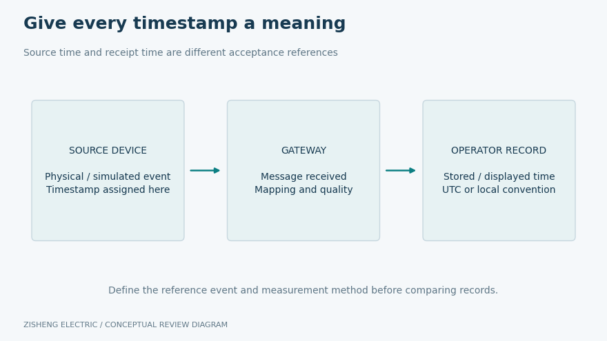
The accepted procedure should establish how a common event or suitable test reference is observed at the devices being compared. Identify the stimulus boundary, source record and receiving record. Preserve the original exports where practical, together with the configuration and time convention needed to interpret them. A cropped screenshot of two nearly matching times rarely provides enough context.
Account for the meaning of the recorded event. Input filtering, application processing and timestamp assignment can affect what two devices report even when their clocks are synchronized. The acceptance method should distinguish those effects from actual timing error. The integrator and device suppliers should explain relevant behavior instead of forcing all differences into a single pass-or-fail clock comparison.
Repeat the agreed observations for the operating states included in the scope. If only one endpoint or path is tested, identify the limits of that evidence. A representative test may be appropriate where the project explicitly accepts it, but the record should explain the selection and remaining coverage. Do not copy one successful device result onto untested units.
The transformer SCADA point-to-point test guide addresses signal identity and the meaning of source and receiving records. Timing acceptance adds a more specific question: can those records be compared on the required common time basis? Keep both acceptance boundaries visible so that correct mapping is not mistaken for proven synchronization performance.
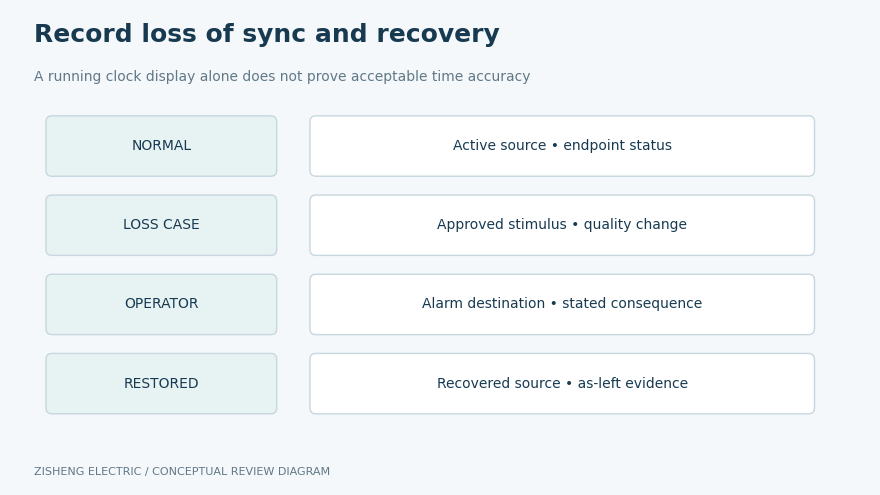
Agree the failure cases before testing. Depending on the architecture, they may concern loss of the selected reference, a distribution-path failure or an approved source change. Use only the authorized commissioning procedure, with the necessary operating restrictions and restoration plan. Unplanned disconnection of a running station network is not an appropriate substitute for a controlled test.
Observe the behavior at the affected endpoint as well as the clock. Record changes in synchronization status, time-quality information and the operator alarm. Where the design specifies holdover behavior, obtain the manufacturer’s conditions and use the agreed verification method. A clock continuing to advance after reference loss does not demonstrate that it remains within the application’s timing requirement.
Check how the system returns to its accepted state. The record should show the recovered source, endpoint status, alarm reset behavior and any restrictions that remain. Some questions require device-specific explanations, including how an adjustment is applied or how historical records identify degraded time quality. Preserve those explanations with the applicable model and firmware reference.
Timing tests may reveal an incorrect time zone, an incompatible profile, a missing alarm mapping or an endpoint attached to the wrong source. Record the discrepancy and the affected configuration. After correction, determine which results need to be repeated. A change that fixes one endpoint can affect other devices sharing the same template or distribution equipment.
Maintain a revision trail from the approved design to the final implementation. The handover package should identify accepted configuration files and the controlled location of backups. Avoid including passwords or other secrets in ordinary test reports; the owner’s approved access process should handle those separately. The engineering record needs enough information to restore the configuration without exposing unnecessary access details.
Close each discrepancy with actual evidence and a named acceptance authority. If the project permits a conditional release, state its scope, operating consequence, owner and completion requirement. A high overall completion percentage should not hide an unresolved timing function that is essential to a particular protection or monitoring application.
The final dossier should include the endpoint register, as-built timing architecture, configuration index, approved criteria, test methods, instrument references, raw results, event exports and discrepancy closures. Identify the time convention used by each exported file. Link the as-left state to the physical equipment tags so that the operator can locate the correct device and record.
Operations staff should know where synchronization alarms appear, what those alarms mean for event interpretation and which support contact owns the affected subsystem. Training should follow the actual installed arrangement. A generic clock manual cannot explain every site-specific gateway mapping, source priority or agreed restriction.
The wider custom engineering interface review can connect the timing scope with the transformer, protection and control packages. For equipment discussions, the 110 kV–115 kV power transformer and 10 kV distribution transformer pages provide starting points. Time-distribution requirements belong to the agreed station system and accessory scope; they are not implied features of every transformer.
No. It can support an observation of display or source status, but acceptance must address the required endpoints, performance claims and failure behavior. The evidence should match the claim. If only a limited inspection was performed, describe it as that inspection and retain the remaining test actions in the handover register.
Send the single-line diagram, station communications architecture, endpoint list, timing requirements, proposed clock models, protocol or profile details, alarm list and commissioning boundaries. Add transformer accessory schedules, auxiliary-supply arrangements, environmental conditions and installation constraints where they affect the interface. Identify the package owners who must approve the final arrangement.
Substation time synchronization acceptance is complete when the owner can trace the reference to the required endpoints, interpret the event records and recognize degraded timing conditions. Zisheng Electric can review transformer accessory and signal interfaces within the agreed supply package. Include the timing boundary in your inquiry so that procurement, integration and handover records remain consistent.

Review substation bolted connection records: verify torque instructions, tool traceability, witness marks and reassembly evidence before EPC handover.
View details
Reconcile substation asset tags with approved equipment schedules, nameplates, drawings, FAT records and commissioning evidence. Use discrepancy classes, owner-controlled data rules and traceable closeout actions to build a usable EPC handover reg...
View details
A commissioning-focused guide to transformer CT secondary circuit handover: core identity, terminal mapping, shorting facilities, polarity records, test boundaries and controlled release to protection systems.
View details
Substation fiber optic acceptance for EPC teams: route records, optical link tests, redundancy, SCADA points and a usable handover dossier.
View details