 zishengelectric



news
News Center
Providing high-quality power to the world
Search productSearch post
news
Providing high-quality power to the world
Trip circuit supervision acceptance should prove that the installed substation can identify the failures its approved monitoring scheme is designed to detect, present the correct alarm, and return to its normal configuration after testing. A healthy indicator alone does not demonstrate that a breaker can trip, that every part of the circuit is monitored, or that the operator receives an actionable warning.
For EPC handover, the main challenge is the boundary between the protection relay, DC distribution, intermediate devices, switchgear wiring and control-room system. This article sets out an evidence framework for that boundary. It is not an instruction to disconnect live protection wiring. All testing must follow the approved equipment-specific method, isolation arrangements, switching authorization and manufacturer documentation.
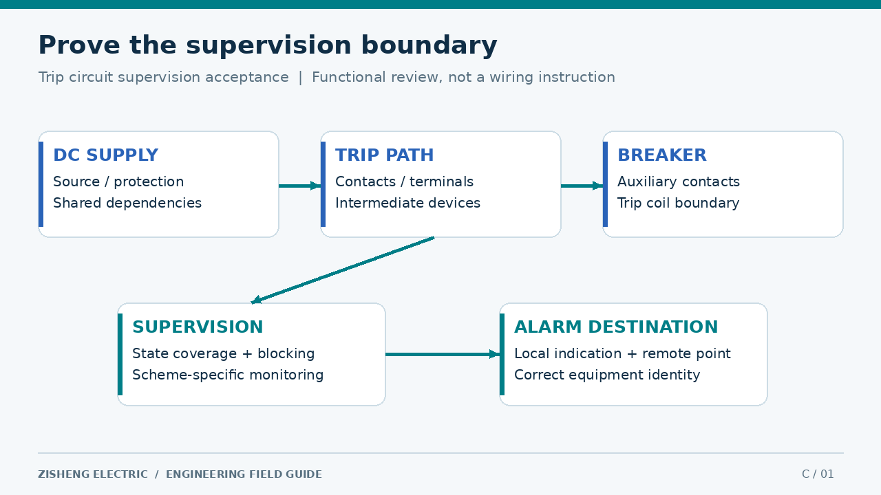
Begin with the approved schematic and identify the DC source, protective devices, trip contacts, any interposing relays, breaker auxiliary contacts, terminal links and trip coil. Mark the points through which the monitoring function assesses circuit condition. Then identify what lies outside that path. A supervision function associated with one relay output should not be described as monitoring every trip path in the bay without evidence.
Manufacturer implementations differ. ABB’s static TCS relay overview describes an arrangement intended to supervise specified failures independently of breaker position. By contrast, the REF615 application example describes blocking associated with master-trip signals and the breaker-open signal. These examples show why the actual scheme and configuration must determine the acceptance cases.
For each supervision channel, write a short statement identifying the circuit monitored, operating states covered, blocking conditions and alarm destination. Attach the controlling schematic and setting revision. If the design supervises only a defined state, record that limitation explicitly. A precise statement of coverage is more useful to operations than a general claim that the complete trip system has been checked.
A supervision alarm test establishes behavior of the monitoring arrangement under a defined condition. A protection trip test establishes operation of a specified protection-to-breaker path under its own test procedure. Breaker mechanical or timing tests establish other aspects of equipment performance. These results may support the same handover dossier, but none should be substituted for the others.
Keep distinct test identifiers and cross-reference their common equipment tags. If an alarm appears correctly while the trip path has not yet been tested, the report should say exactly that. Similarly, successful breaker operation does not prove that a broken wire or supply-loss condition will be annunciated. The commissioning manager should review completeness across these scopes before recommending release.
The wider high-voltage switchgear commissioning framework provides the surrounding installation and functional context. The present acceptance review focuses on the monitoring evidence, its blind spots and its final restoration record.
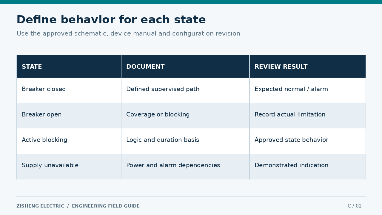
Define expected behavior for every relevant breaker and scheme state before testing begins. At minimum, review the intended open and closed conditions, active blocking conditions, available and unavailable auxiliary supply, and the normal versus test configuration. Not every design supports identical supervision in each state. The matrix must describe the installed arrangement rather than impose behavior copied from another relay family.
Include channel identity where a breaker has more than one trip coil or where protection groups use separate circuits. Identify whether an alarm is individual or grouped and what information the operator receives. Two labels on a screen are not evidence of independent DC sources or independent circuits; independence must be established from the design and installation records.
Specify the expected local indication, remote text, assertion and clearance behavior, applicable delay, timestamp source and operator acknowledgment rules. Use approved project settings and manufacturer limits for numerical criteria. Avoid an arbitrary universal alarm delay. A delay that prevents unwanted indications during normal operation still needs to meet the project’s monitoring requirements and be supported by the selected equipment.
Trace the supply feeding the monitored trip circuit and the supply feeding the monitoring device, alarm relay, communications equipment and display. A loss of one source may affect several parts of the chain. Ask how the operator learns of that loss if the local device or communications path becomes unavailable at the same time. The answer must follow the installed architecture and its defined failure indications.
Coordinate this review with the substation DC battery commissioning evidence. Battery capacity, charger performance, outgoing DC feeder protection and voltage at the critical load are related matters with separate evidence. A satisfactory supervision indication cannot replace verification of the DC system’s ability to supply the required operating duty.
Document any shared source, shared fuse, shared terminal or shared communications dependency that matters to the acceptance claim. The objective is not to redesign the system during a test. It is to confirm the approved arrangement, identify discrepancies and refer design concerns to the responsible engineer. Unresolved dependencies should remain visible in the handover limitations.
The approved method should define the equipment identity, drawing revision, starting state, permitted simulation points, isolation boundary, expected results, personnel responsibilities and abort conditions. Specify how accidental operation is prevented within that method. Test activities that affect protection require coordination with the authorized operating organization; an EPC worksheet does not itself authorize switching or removal of a protection function.
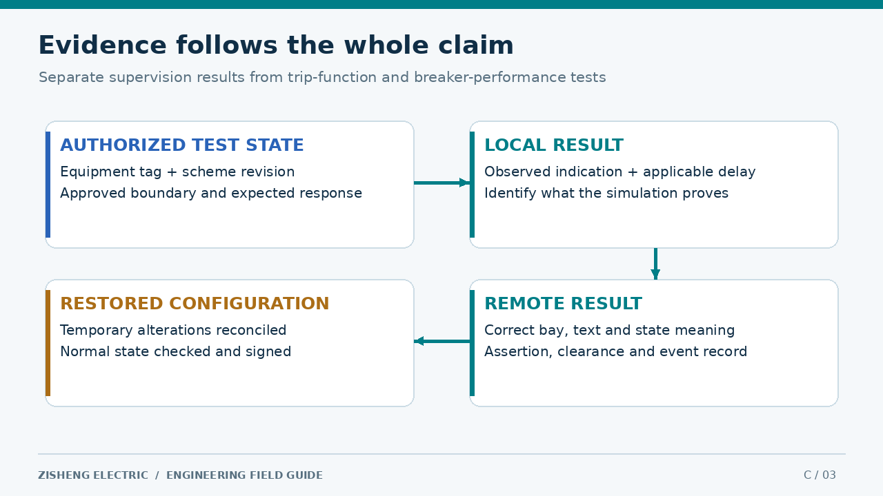
Where simulation is used, state what it proves and what remains untested. For example, a simulated input can demonstrate alarm logic and display mapping while leaving part of the field circuit unverified. The report should identify the injection or simulation boundary and cross-reference the separate field evidence. This prevents a convenient test point from being mistaken for full end-to-end coverage.
Maintain a controlled register for temporary links, isolation points, test plugs, forced signals and setting changes introduced under the approved procedure. Assign one restoration check to each item. Temporary conditions should not disappear into handwritten notes without an owner. Before the bay is released, the final circuit and software state must be reconciled against the approved operating configuration.
| Review case | Required evidence | Acceptable conclusion | Action if unresolved |
|---|---|---|---|
| Healthy circuit in a supervised state | State, configuration and normal indication | Normal behavior matches the approved scheme | Investigate unexplained alarm or blocking |
| Approved simulated failure | Defined boundary, expected delay and observed alarm | The specified monitoring path responds | Keep the affected acceptance item open |
| Breaker state with intentional blocking | Logic revision and blocking indication or evidence | Documented coverage limitation is understood | Resolve mismatch with the design authority |
| Auxiliary supply unavailable | Dependency review and approved test results | The stated source-loss behavior is demonstrated | Investigate silent or ambiguous failure indication |
| Remote alarm differs from local result | Point identity, mapping, timestamps and event record | Only the verified part of the chain is complete | Correct mapping and repeat affected tests |
| Test complete but temporary changes remain | Alteration register and restoration checks | No release until required restoration is verified | Hold the relevant handover gate open |
Record the originating equipment tag, supervision channel, terminal or logical point reference, gateway mapping and displayed alarm text. Confirm that the message identifies the correct bay and circuit. A generic group alarm may be acceptable under the approved design, but the operating procedure must explain how the underlying condition is located. Avoid describing a group indication as a detailed diagnosis.
Retain evidence of assertion, acknowledgment where applicable and return to normal. Check the meaning of both normal and abnormal states; reversed text can make a successful electrical test misleading to the control-room operator. Where communications quality becomes invalid, the display should behave according to the accepted system design. A stale healthy value must not be accepted simply because its color remains normal.
Event timestamps should be interpreted using the project’s clock architecture and acceptance criteria. Distinguish the time the device detects a condition from the time a gateway or workstation records it. Screenshots are useful supporting evidence, but the record should also identify the test case, settings revision and observed sequence. This allows later reviewers to understand what the image actually demonstrates.
Classify defects by their effect on the stated acceptance scope. An incorrect alarm tag, an unexpected blocking condition and a missing field connection are different problems requiring different owners. Record the equipment affected, observed behavior, expected behavior, evidence reference and agreed action. Avoid closing several unlike defects under one vague statement that the system was checked again.
After a correction, determine which tests are affected by the change. A display text correction may need a targeted mapping retest; a revised supervision logic or circuit connection may require a wider state review. The responsible engineer should define that scope. Preserve the failed result, the correction reference and the successful retest rather than replacing the history with an undated clean sheet.
Consider a hypothetical bay in which the local supervision indication behaves as expected in the tested closed state, but the control-room message identifies the adjacent bay. During the document review, the team also discovers that the open-state behavior was copied from a different project. This is an illustrative scenario, not a claim about a delivered Zisheng installation.
The team keeps two actions separate. The integrator corrects the point identity and repeats the affected end-to-end indication test. The protection engineer checks the installed schematic and settings, then revises the state matrix to reflect the actual supervision and blocking arrangement. Any additional testing follows the newly approved scope. A correctly displayed alarm alone would not have resolved the inaccurate statement of coverage.
The final record includes both original discrepancies, approved corrections, repeated results and confirmation of normal configuration. The owner receives a clear explanation of what is monitored in each state and which separate records prove tripping and breaker operation. That is stronger evidence than an unsigned checklist marked “TCS OK.”
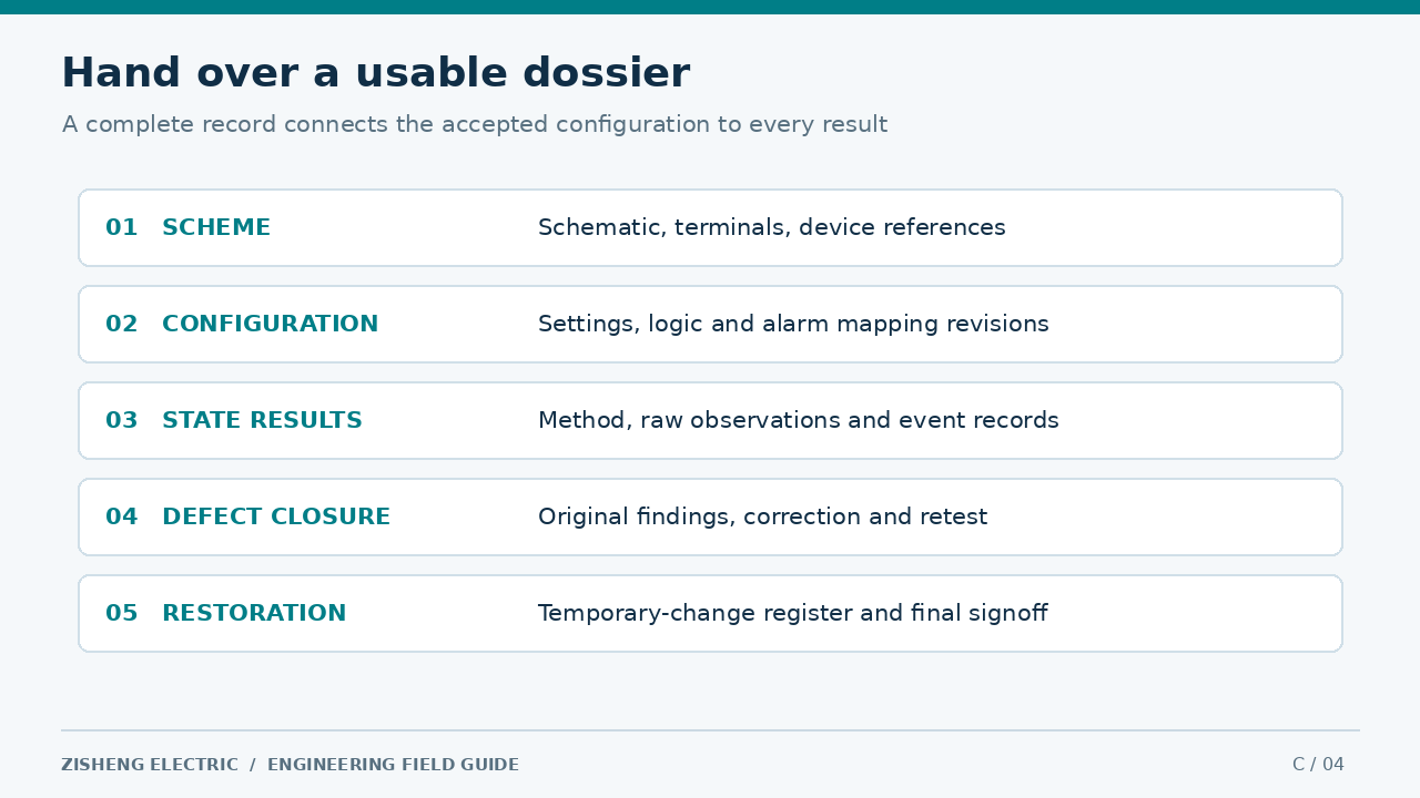
The handover index should include the approved schematic, terminal drawings, device manual references, relevant configuration and settings revisions, state matrix, test method, raw observations, event records, alarm mapping, defect log and restoration signoff. Link each record to the breaker and supervision channel. File names and report identifiers should remain meaningful after the commissioning team leaves the site.
Operations also needs the alarm response procedure and maintenance responsibilities. Identify who assesses a supervision alarm, how the affected protection arrangement is evaluated under the operating rules, and where the current scheme documents are stored. Do not embed an improvised switching sequence in the article or in a generic handover summary. The authorized site procedure controls operational decisions.
Does each channel have a documented boundary? Are open, closed and blocked states described accurately? Is the source-loss behavior understood? Do local and remote indications agree with the approved point list? Are separate trip-function records cross-referenced? Are defects closed with evidence and all temporary changes reconciled? Unanswered questions should identify an owner and an explicit release decision.
For an EPC interface review with Zisheng Electric, provide the single-line diagram, trip schematics, DC distribution arrangement, supervision device details, alarm list and proposed acceptance matrix. These inputs allow the transformer, switchgear and integration teams to define responsibilities and produce a handover package that operators can use.
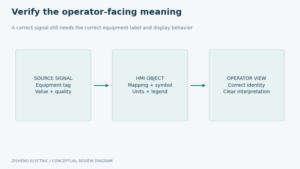
Plan substation HMI mimic acceptance with equipment labels, status interpretation, measurement meaning, data-quality checks and controlled handover records.
View details
Plan substation revenue metering handover with verified CT/VT ratios, register mapping, time conventions and end-to-end data evidence. Define utility acceptance, configuration custody and the records needed for EPC closeout.
View details
Build a substation temporary modification register that connects approved test changes to baseline records, restoration checks and release evidence. Review ownership, shift handover, configuration reconciliation and operator turnover.
View details
A commissioning-focused guide to transformer CT secondary circuit handover: core identity, terminal mapping, shorting facilities, polarity records, test boundaries and controlled release to protection systems.
View details