 zishengelectric





news
News Center
Providing high-quality power to the world
Search productSearch post
news
Providing high-quality power to the world
Zisheng Electric treats a transformer noise control plan for EPC substations as an interface document, not merely a guaranteed sound-level line in the transformer data sheet. The transformer, building, foundation, ventilation system, cable openings, property boundary and operating schedule all influence what people finally hear. A technically acceptable transformer can still create complaints or fail a site requirement when the acoustic basis is unclear or when civil and mechanical interfaces amplify the sound.
This guide explains how EPC teams can turn an acoustic requirement into measurable equipment, layout and acceptance criteria. It is intended for substations serving utilities, industrial plants, renewable-energy facilities and infrastructure projects. Any numerical limit must come from the project specification, applicable local regulation and approved acoustic study; the examples below are planning examples, not universal limits.
Transformer sound is produced mainly by magnetic forces in the core, electromagnetic forces in windings and structural components, and cooling equipment such as fans and oil pumps. The resulting tonal and broadband components can travel through air, foundations, walls, ducts and connected structures. The measured result depends on transformer loading, system voltage, tap position, cooling stage, background sound and the measurement location.
This is why the procurement team should not ask only for “low noise.” It should define where the requirement applies, which operating condition is relevant, which cooling equipment is running, how background sound will be handled, and who owns mitigation outside the transformer boundary. Without these points, suppliers may quote different acoustic bases and the EPC contractor may discover the gap only after installation.
The first step is to separate equipment sound performance from environmental compliance. A transformer manufacturer can state and demonstrate equipment sound characteristics under an agreed method. Compliance at a control-room wall, residential receptor or site boundary also depends on distance, barriers, terrain, buildings, reflections, weather and simultaneous plant sources. The EPC acoustic consultant or responsible designer should therefore convert the site criterion into an equipment sound budget.
For a brownfield project, baseline measurements are especially valuable. Existing generators, cooling towers, traffic, process machinery and neighboring transformers may dominate the background. For a greenfield site, the model should consider future units and credible simultaneous operation rather than one transformer in isolation.
| Input | Information to define | Engineering effect | Risk if omitted |
|---|---|---|---|
| Compliance location | Transformer perimeter, building façade, control room, property boundary or external receptor | Sets propagation distance and acceptance point | An equipment result is mistaken for site compliance |
| Operating case | Energized no-load, specified load, cooling stage, parallel units and auxiliary equipment | Determines the credible source condition | Testing is performed under a quieter, nonrepresentative state |
| Acoustic metric | Required sound quantity, frequency treatment, averaging time and correction method | Makes bids and tests comparable | Different metrics appear similar but cannot be reconciled |
| Site geometry | Distances, elevations, walls, buildings, doors, louvers, ducts and cable penetrations | Controls reflection, screening and leakage | Architectural details defeat the predicted attenuation |
| Structural path | Foundation design, rails, resilient interfaces, busduct and pipe connections | Influences structure-borne vibration | Vibration bypasses airborne-noise measures |
| Background sound | Survey method, operating sources and agreed correction approach | Supports repeatable site measurements | Acceptance result is inconclusive |
| Responsibility boundary | Transformer supplier, enclosure supplier, civil designer, HVAC contractor and commissioning team | Assigns each mitigation and verification action | Critical work remains outside every package |
A useful specification identifies the transformer rating, voltage and frequency basis, flux conditions, tap position, load state and cooling mode associated with the acoustic guarantee. Cooling equipment should be addressed separately because fan noise can change the sound character and may govern the result when forced cooling operates. If the transformer has staged fans, the control philosophy and the acoustic case should agree.
System overvoltage and off-nominal frequency can increase core excitation. Procurement documents should therefore define the permitted voltage and frequency envelope and identify which condition is used for the guaranteed sound assessment. The EPC team should coordinate this with the transformer design review rather than adding an isolated noise note late in manufacturing.
Where the project invokes IEC or another standard, cite the exact applicable edition in the approved specification and define any project-specific additions. Do not assume that a standard reference automatically sets the environmental limit at the site boundary. The transformer test method and the environmental compliance method are different parts of the acceptance chain.
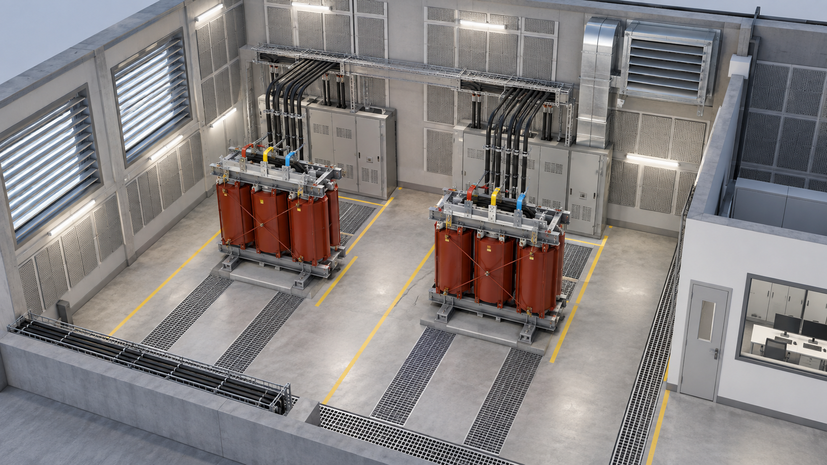
Distance, orientation and barriers should be evaluated before complex equipment modifications. Locate the transformer away from noise-sensitive rooms where the site permits. Avoid directing radiator banks, cooling fans, open doors or ventilation louvers toward occupied areas. A solid barrier can be effective only when its height, length and position interrupt the relevant line of sight and when gaps do not create a direct leakage path.
Indoor substations need particular attention to reverberation. Hard walls, floors and ceilings reflect sound. Acoustic lining may help, but its fire performance, durability, contamination resistance and maintenance access must be reviewed. Louvers and ventilation openings can become dominant escape paths. Silencers may reduce leakage, yet they also add pressure drop. The HVAC designer must confirm airflow and transformer thermal performance after acoustic treatment is included.
For equipment positioning and construction release, coordinate the acoustic plan with the transformer foundation interface review. The approved layout should show transformer centerlines, radiator and fan orientation, wall positions, door swings, maintenance clearances and cable routes. Acoustic measures that block radiator airflow or lifting access create a new operational problem.
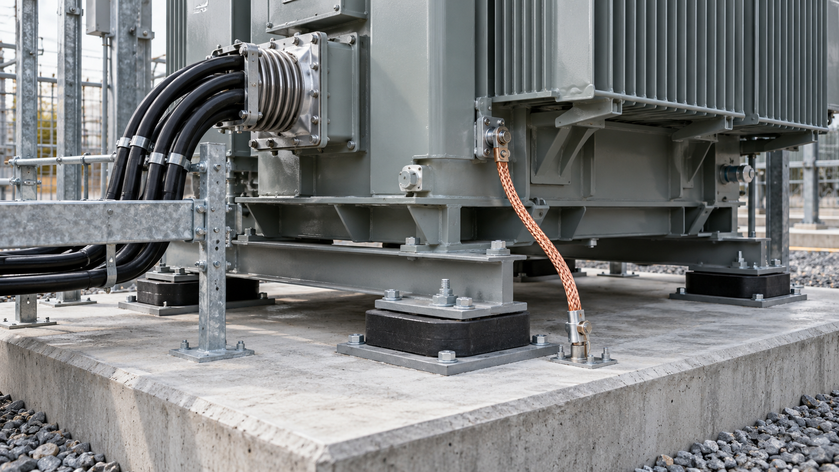
Airborne sound receives most attention, but vibration can enter the foundation and re-radiate through walls or floors. The structural engineer should evaluate equipment mass, center of gravity, support points, stiffness and dynamic behavior. If resilient mounts or isolation pads are proposed, their loading range, environmental resistance, long-term compression, seismic implications and installation tolerances must be reviewed as a complete system.
Rigid connections can bypass isolation. Busducts, cable supports, oil pipes, fire-system piping, earthing conductors and auxiliary conduits should not create unintended vibration bridges. Flexible elements must remain electrically and mechanically suitable; acoustic convenience must never compromise fault-current withstand, earthing continuity, oil integrity or fire safety.
Interface drawings should identify which party supplies each pad, flexible connector, support and embedded item. These details belong in the coordinated design package and the EPC transformer document register, not in an informal site instruction.
During bid evaluation, normalize acoustic submissions. Confirm whether the stated value includes cooling equipment, which measurement surface and method apply, and whether tolerances or uncertainty are addressed. Ask bidders to list any assumptions about enclosure, background conditions or site attenuation. A lower headline number is not necessarily a better proposal if the basis differs.
The technical bid tabulation should also review losses, impedance, temperature rise, dimensions, mass, accessories and cooling controls. Noise mitigation can affect other parameters. A revised core design may change size or cost. Additional fans may affect auxiliary power and control interfaces. An enclosure may change cooling, access and fire strategy. EPC selection should therefore balance the acoustic requirement with the complete electrical and mechanical design.
Hypothetical specification example — values and acceptance limits must be replaced with project-approved data.
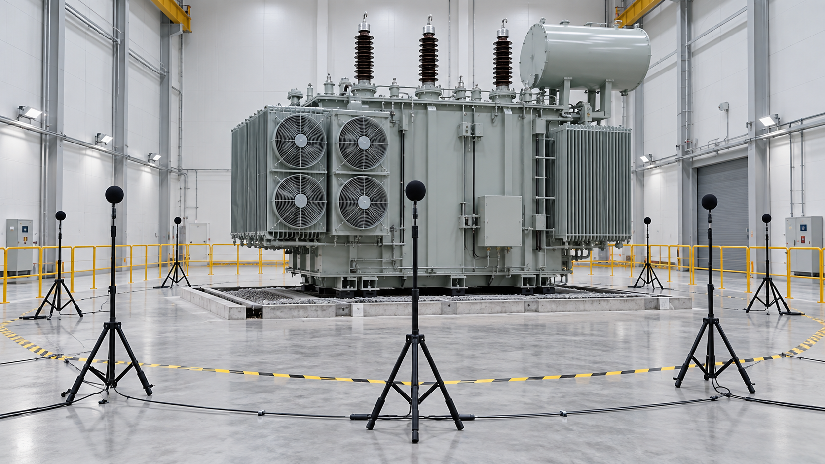
The inspection and test plan should define the acoustic test stage, notice period, document prerequisites, instrumentation records, operating configuration and acceptance authority. Factory conditions may differ from the final site, so the procedure should state how reflective surfaces, background sound and adjacent operating equipment are addressed. The test report should record transformer identification, rating, applied voltage and frequency, tap position, cooling status, measurement positions, background readings and final calculated results.
Acoustic verification should be coordinated with the broader transformer inspection and test plan. If a result is outside the agreed criterion, the parties need a defined path for data review, repeat measurement, corrective action and release. Shipping should not proceed on the assumption that a site barrier will solve an unresolved equipment deviation unless the owner has formally approved that change.
Before site measurements, confirm that assembly is complete, foundations and supports match approved drawings, cooling equipment is operational, doors and louvers are in their normal positions, and nearby temporary machinery is controlled. Record weather and background conditions. The measurement plan should state whether other transformers and plant loads are operating.
If a site result differs from the prediction, diagnose the path before changing equipment. Check supply voltage and frequency, cooling-stage status, loose panels, fan balance, rigid connections, open penetrations, building reflections and unexpected background sources. Compare frequency characteristics where available. Tonal peaks can help distinguish core-related sound, fan components and structural resonances.
The closeout package should include the approved acoustic basis, supplier guarantee, factory report, installed-condition inspection, site readings, deviations, corrective actions and final acceptance. Link any open items to the project punch-list process and energization authority.
The most common risk is an ambiguous requirement copied from another project. The second is a responsibility gap: the transformer supplier assumes the EPC contractor will provide an enclosure, while the EPC contractor assumes the transformer alone will meet a boundary limit. A third risk is late architectural change. Moving a louver, deleting a barrier or adding a rigid busduct support can invalidate the acoustic model.
Control these risks with an approved interface schedule, model inputs frozen at a defined milestone, formal review of changes and evidence-based acceptance. Keep the acoustic requirement traceable from owner specification through supplier data, civil and HVAC drawings, factory testing, installation and final handover.
A successful transformer noise control plan for EPC substations connects the transformer specification with layout, structural design, ventilation, testing and site acceptance. Zisheng Electric can review transformer and substation equipment requirements alongside the relevant interface information for oil-immersed power transformers, dry-type transformers and associated medium-voltage switchgear.
For an engineering review, provide the drawings, transformer data sheet, load list, technical specification, single-line diagram, grid parameters, environmental conditions, acoustic study or limits, building arrangement and installation-site conditions. Relevant equipment options may include a 35kV–46kV power transformer, a dry-type transformer, and 3kV–10kV medium-voltage switchgear. “Our engineering team will review the requirements and respond to project inquiries within 24 hours.”
Build an EPC transformer document register that controls submittals, revisions, approval codes, manufacturing release, FAT records, logistics files and final handover evidence.
View details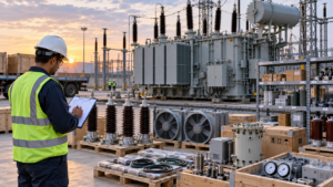
Build an EPC transformer spare parts list with checks for component compatibility, stock scope, preservation, traceability and maintenance handover.
View details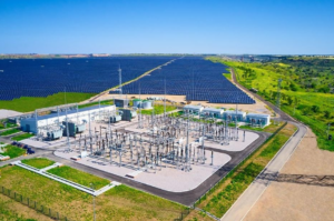
Why Tropical-Ready Design Determines Project Reliability A transformer failure in a Vietnamese coastal industrial park or a Thai solar farm is never just a component issue. Production halts. Revenue slides. The unplanned maintenance costs no proje...
View details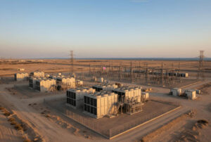
Power infrastructure across Saudi Arabia, the UAE, Qatar, and Oman operates under conditions that would quickly derate or destroy standard electrical equipment. In these environments, transformer failure is rarely a manufacturing defect—it is almo...
View details