 zishengelectric





news
News Center
Providing high-quality power to the world
Search productSearch post
news
Providing high-quality power to the world
At Zisheng Electric, transformer radiator assembly verification starts with a practical question: does the cooling circuit installed at site match the configuration the equipment was designed to use? A radiator can be securely bolted to the tank while its identity, internal condition, isolation state or completion record remains unresolved. Those gaps matter when the erection contractor hands the transformer to the oil-processing or commissioning team.
This engineering briefing is for EPC engineers, installation supervisors and equipment buyers reviewing detachable radiators on oil-immersed transformers. It follows the physical cooling circuit through four acceptance decisions: identify the parts, accept the mechanical interfaces, reconcile the processing configuration and record the final operating arrangement. The approved manufacturer instructions govern the work itself; tightening values, vacuum limits and valve sequences must remain specific to the supplied unit.
First establish which equipment the inspection covers. A detachable radiator bank, a corrugated tank wall and a separate forced-oil cooler are different arrangements. Do not apply the same checklist without checking the drawings. Identify the transformer tag, radiator location, upper and lower connections, supports, vents, drains and any fans or pumps included in that cooling circuit.
The immediate objective is a traceable release to the next activity. Mechanical assembly completion does not establish oil-processing acceptance, prove cooling performance or authorize energization. Each receiving team needs to know what has been checked and what is still outstanding. Otherwise, a signed erection sheet can become an unjustified substitute for several separate acceptance decisions.
Bring together the approved general arrangement, cooling-system drawing, packing list, component identification schedule and installation manual. Add the inspection plan and any accepted design changes. Check that the documents describe the actual shipping arrangement: a drawing showing the finished transformer may not show temporary blanks, transport supports or separately packed connecting pieces.
The official description of IEC 60076-1:2011 identifies transport, liquid preservation and tank vacuum, pressure and leak tests among its technical subjects. That general scope does not supply the site procedure for an individual radiator. The project must identify the applicable contractual references and obtain the component-specific limits from the manufacturer before work begins.
Match each radiator to its intended transformer and installation location before staging it beside the tank. Compare component marks, packing references, flange geometry, connection spacing and support details with the approved documents. Similar appearance is insufficient where two transformers have different cooling arrangements or where a replacement component has a revised design.
Record the condition of the transport protection as part of that check. Missing or disturbed blanking plates create a question about preservation and cleanliness that a paint inspection cannot answer. Document the observation and refer it for disposition. Do not assume a component is internally acceptable because the exterior is dry, or remove protective covers simply to make the receiving inspection look more complete.
Check the supplied gasket sets, fastening hardware, valve accessories and supporting parts against the relevant bill of materials. A missing gasket is not a purchasing detail to resolve with an approximate local substitute. Its material, dimensions and service compatibility belong to the approved joint design. Keep substitutions under the manufacturer’s review and the project’s change-control process.
The broader transformer site assembly supervision plan should assign responsibility for these checks. For the radiator package, add a location-based record so the inspection follows each component through unpacking, installation and release rather than ending at the crate count.
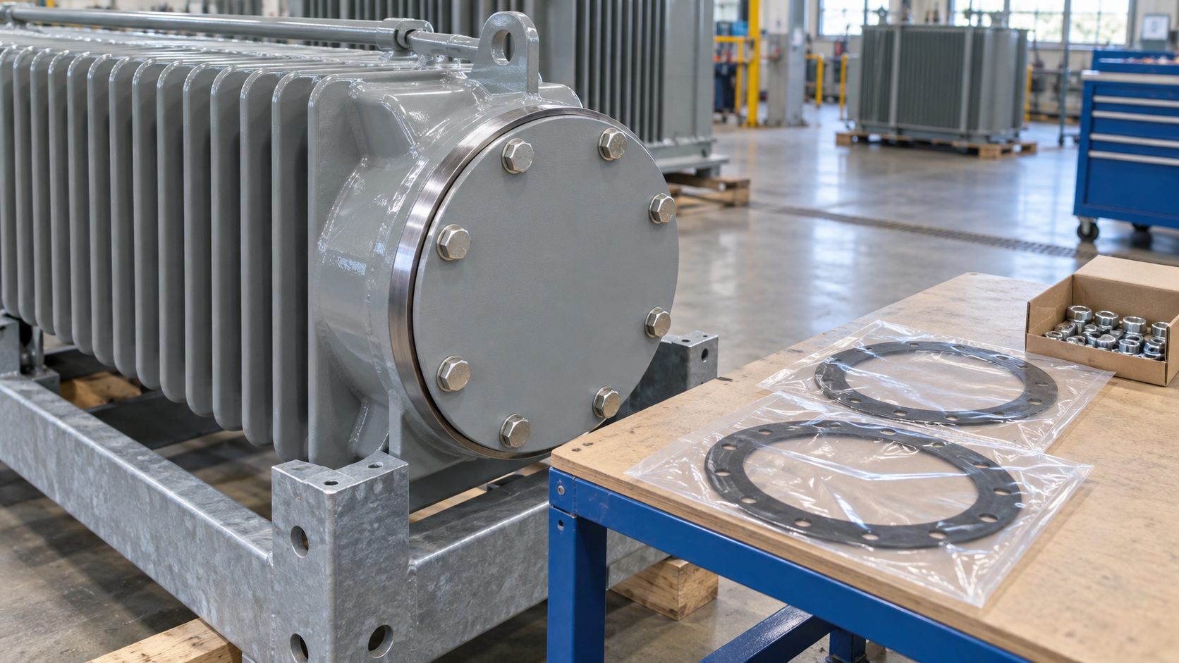
Review alignment while the intended supporting arrangement can still be inspected. A flange joint should not become the means of pulling a misaligned radiator into position. Forced alignment can conceal a dimensional problem and introduce loads that were not part of the intended arrangement. Record the mismatch, protect the equipment and obtain a disposition before the joint is accepted.
The inspection should distinguish temporary handling supports from permanent supports. Confirm which pieces remain, which are removed and when their removal is permitted. Check the supporting surfaces and attachment points against the approved drawing. Do not infer that a visible steel bracket is optional because the radiator appears to remain upright without it.
Identify each specified joint by location and record the approved gasket reference, relevant installation instruction and required fastening evidence. Where torque recording is required, retain the specified value, tool identification and execution record under the project procedure. A paint witness mark can help reveal movement; it cannot establish the original tightening condition on its own.
Photographs are useful when they show orientation, support details and access before adjacent equipment obstructs the view. They should supplement the inspection record, not stand in for it. Record any limitation honestly. An inaccessible lower connection should be addressed in the work sequence rather than accepted on the strength of a distant photograph.
The following table supports engineering disposition. It deliberately contains no universal pressure, torque or time limits. Those values belong in approved project and manufacturer documents. The important distinction is whether an observation can be closed by an identity check, needs a mechanical correction or prevents release to the next activity.
| Finding | Why it affects the decision | Evidence needed | Release action |
|---|---|---|---|
| Component mark does not match its allocated position | Similar radiator banks may have different interfaces or duties. | Approved cooling drawing, packing reference and manufacturer confirmation. | Hold that component’s installation until the allocation is resolved. |
| Flange alignment requires force | The connection may carry unintended stress or hide a dimensional mismatch. | Measured mismatch, support condition and approved corrective disposition. | Refer for correction before accepting the joint. |
| Gasket identification is missing | Appearance does not establish material or fluid compatibility. | Traceable part reference and approved substitution, if any. | Do not close the joint record on an assumed equivalence. |
| Preservation cover was disturbed in storage | Internal cleanliness and moisture exposure may be uncertain. | Storage history, condition report and manufacturer-directed assessment. | Resolve the preservation question before processing release. |
| Valve position record conflicts with the field indication | The processing or operating circuit may differ from the intended state. | Valve identity, approved state schedule and competent verification. | Reconcile the discrepancy under the authorized procedure. |
| A joint is reopened after its leak check | The earlier result no longer demonstrates the rebuilt joint’s condition. | Rework details and the required repeat verification. | Reopen the affected acceptance item and close it with new evidence. |
| Fan frame obstructs a service point | A completed installation may prevent later inspection or maintenance. | Access review and approved arrangement revision. | Resolve access before final mechanical handover. |
Before oil processing begins, define the exact boundary of the procedure. Establish which radiators, connecting pipes and accessories are included, their permitted pressure or vacuum conditions and the required isolation states. A main tank’s capability must not be assumed to apply automatically to every attached component. Resolve an unclear boundary with the manufacturer before connecting processing equipment.
Keep a state schedule for identified valves and temporary blanks. The schedule should distinguish transport, assembly, processing, testing and final service configurations wherever they differ. It should name the person responsible for verifying a change and the document that authorizes it. This is more useful than an instruction to check that all valves are simply “open” or “closed.”
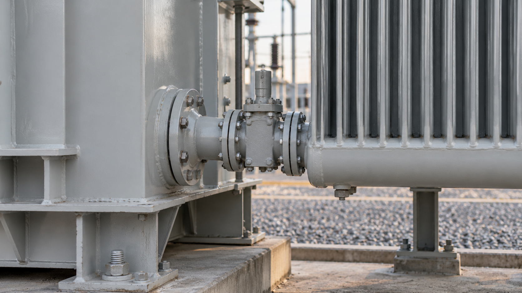
The oil-processing team needs the accepted circuit boundary, outstanding findings and any approved limitations. Its records should reference the same equipment locations used by the erection team. Completion of filling, air removal and related checks must follow the approved method for that arrangement. Do not infer their completion from a tank-level indication alone.
Our transformer oil-filling and handover guide addresses the wider processing activity. Radiator verification supplies a specific input to that activity: evidence that the intended cooling circuit is correctly assembled and that its condition and boundaries are understood.
After the prescribed processing and leakage checks, reconcile the installed arrangement with the final drawing. Record required valve states, closure of vents and drains, removal of temporary items and acceptance of any repaired joints. Apply the approved verification method; neither a photograph of a handle nor a generic checklist tick should override a contradictory field observation.
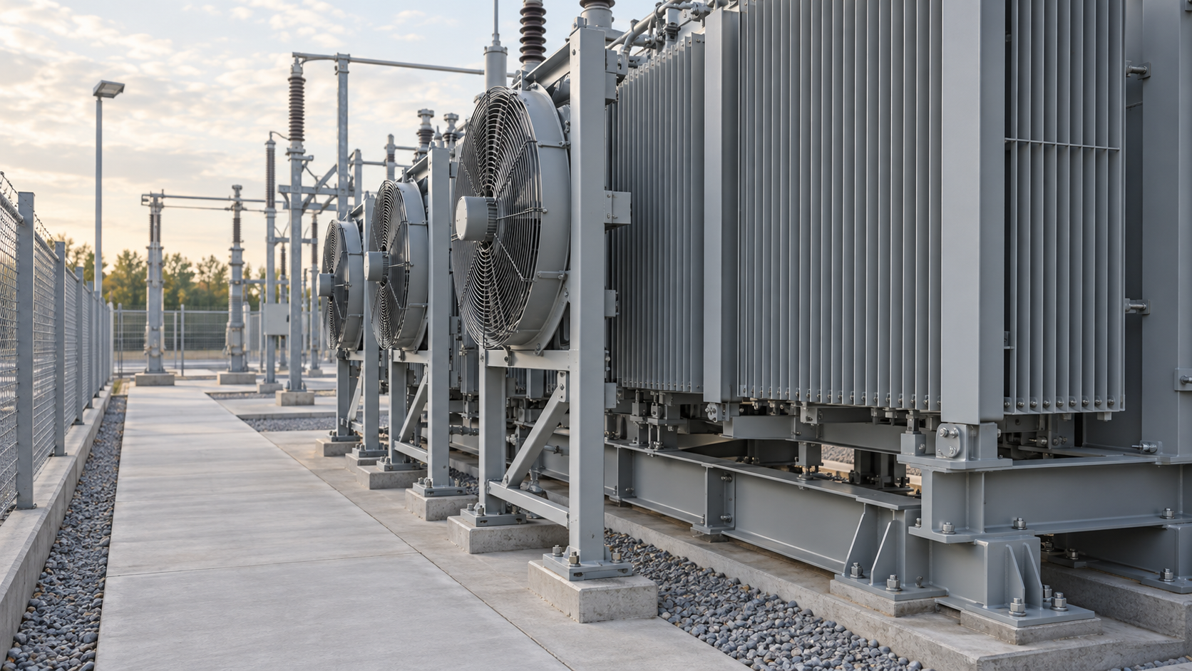
Where fans or pumps are fitted, mechanical completion and functional completion need separate evidence. The mechanical review covers mounting, guards, cable support and service access. The authorized functional procedure checks the intended equipment response and its associated controls. A running fan does not demonstrate that every cooling stage, alarm or remote indication has been verified.
If a leak is repaired or a component is replaced, identify which earlier records are affected. Close the repair with the verification required by the approved method and update the equipment or part reference where necessary. Do not leave the handover team to reconcile a new component with an old inspection sheet that describes a different configuration.
A useful final package contains the radiator allocation record, accepted assembly checks, valve-state schedule, processing references, leakage results, rework closures and the final arrangement drawing. Keep open items explicit, with a responsible person and release consequence. The handover signature should describe the accepted scope rather than imply that the whole transformer is ready for energization.
Ask the receiving engineer to choose one radiator bank and trace it from the packing list to its installed position, its joint records and the final valve-state entry. Then choose a repaired connection and locate the evidence that closed it. If either trail depends on somebody remembering what happened, the package is not yet easy to use.
Consider a hypothetical delivery containing two visually similar radiator sets. One bank is initially staged beside the wrong transformer, then returned to its correct position before installation. The physical outcome may be acceptable, but the allocation sheet and photographs still need correction. A later reviewer should be able to distinguish a corrected staging error from an unapproved component exchange without reconstructing the day from informal messages.
Zisheng Electric’s 220kV/230kV power transformer offering includes project-specific cooling and shipping arrangements. For distribution applications, the 20 kV-class oil-immersed distribution transformer is another equipment reference. Confirm the actual supplied cooling construction; detachable-radiator inspection requirements should not be copied automatically to an integral cooling-wall design.
For transformer radiator assembly verification and supply-scope review, send your drawings, datasheets, load list, technical specifications, single-line diagram, grid parameters, environmental conditions and installation-site conditions. Include the proposed shipping configuration, erection responsibilities and maintenance-access constraints where available. Our engineering team will review the requirements and respond to project inquiries within 24 hours.
Reliable Transformer Supply for Renewable Energy, Industrial, Utility, and Infrastructure Projects For EPC contractors, the decision of which transformer manufacturer to work with can shape how the entire project unfolds. A transformer is just one...
View details
Power infrastructure across Saudi Arabia, the UAE, Qatar, and Oman operates under conditions that would quickly derate or destroy standard electrical equipment. In these environments, transformer failure is rarely a manufacturing defect—it is almo...
View details
After years of working on-site with EPC projects, I have realized one critical truth: although transformers seem to be standard electrical equipment, every actual project requires customized support. Tiny differences in design parameters, dimensio...
View details
Build a transformer DGA baseline for EPC handover: connect oil history, sample identity, laboratory methods and first-service review responsibilities.
View details