 zishengelectric





news
News Center
Providing high-quality power to the world
Search productSearch post
news
Providing high-quality power to the world
In EPC work, a transformer room can look complete on a drawing and still be impossible to maintain on site. Zisheng Electric engineers review the room as an operating space, not only as a rectangle around the tank. The transformer, switchgear, cables, cooling air, lifting route and safety clearances must work together from energisation through years of maintenance.
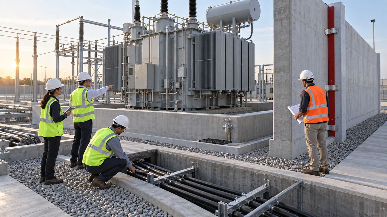
Insufficient clearance can prevent radiator removal, bushing inspection or cable termination work. Poor ventilation raises winding and oil temperatures. A door that is wide enough for installation may still block a future replacement route. These are EPC interface failures: the electrical equipment is correct, but the civil and mechanical conditions do not support it.
The layout should be coordinated with the approved transformer GA drawing, switchgear arrangement, cable schedule, fire strategy and lifting plan. Do not freeze the room using a generic equipment outline when the final transformer weight, radiator projection and terminal orientation are not approved.
Maintain the clearances required by the project specification and utility rules around bushings, cable boxes and exposed connections. The highest system voltage and insulation level govern the design basis. Keep temporary construction access in mind; a clearance occupied by scaffolding is not available during testing.
Air must enter and leave the room without short-circuiting around the transformer. Check louvre position, fan direction, radiator spacing and heat rejection to adjacent rooms. If forced cooling is specified, show fan power, control wiring and a safe maintenance position. A room calculation based on average outdoor temperature can be misleading when solar gain and restricted airflow are present.
Provide a route for oil drainage, accessory replacement and removal of radiators or coolers. Confirm crane beam capacity, door height, turning radius and floor loading. The route should be drawn from the unloading point to the foundation, not described only in a method statement.
Coordinate cable bending radius, gland-plate entry, marshalling box location and control-panel access. The substation cable interface schedule should use the same terminal numbering and orientation as the transformer schematic.
| Layout input | Common failure | EPC check |
|---|---|---|
| Transformer GA and weight | Radiator or lifting route conflicts with walls | Use approved outline, shipping dimensions and lifting points |
| Ventilation calculation | High room temperature and thermal derating | Check heat losses, airflow path, louvres and fan duty |
| Cable schedule | Terminations exceed bend radius or block access | Coordinate gland plate, phase spacing and removable covers |
| Fire and oil containment | Drainage or access conflicts with bund walls | Review the oil containment design with civil drawings |
| Replacement route | Future outage requires demolition | Prove door, turning, lifting and floor-load conditions |
Transformer rooms are part of the source-to-load chain. Incoming switchgear, busduct, LV boards and protection panels need working space and safe isolation. Keep control cables away from high-current routes where practical, and reserve access for testing CT circuits, trip coils and alarm contacts. The EPC project supply scope should identify who provides each interface drawing.
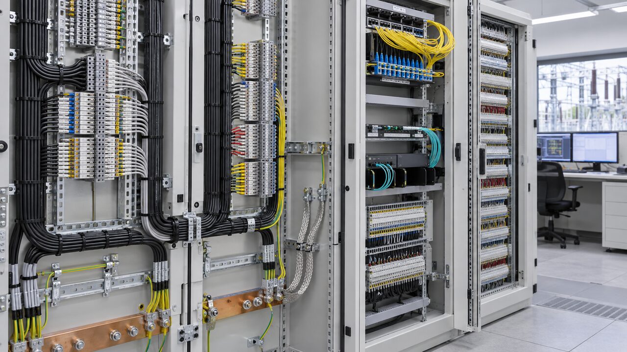
Before civil release, issue a coordinated room drawing showing foundation bolts, cable trenches, doors, ventilation openings, fire barriers, earthing points, lighting and drainage. At site, check foundation level, embedded items and cable-trench cleanliness before delivery. Photograph hidden works for the handover dossier.
During our design reviews, we ask the EPC team to mark the maintenance position of every removable component. This simple exercise often reveals a wall, pipe or tray that was invisible in a top-view layout. It is cheaper to move a tray before concrete than to modify a live substation.
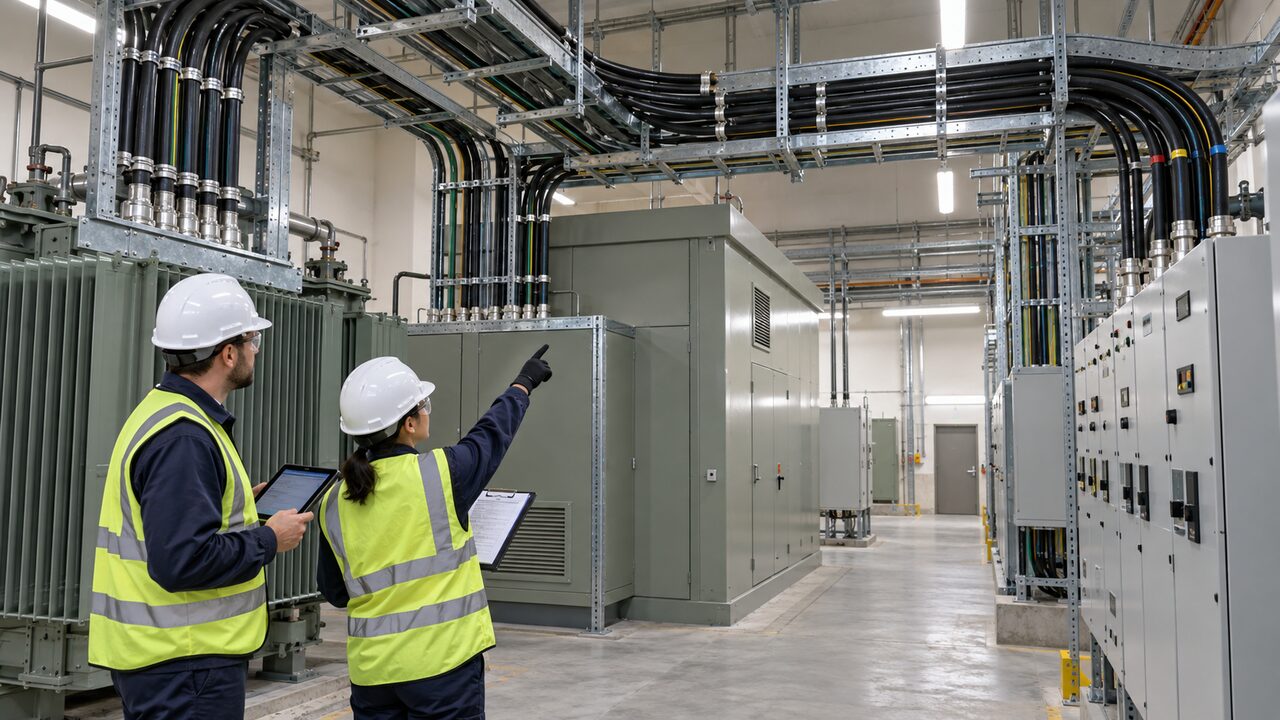
The room layout should be referenced in the inspection and test plan, packing list and installation method statement. Record transformer serial number, final dimensions, shipping weight and accessory list. At handover, include insulation and winding test records, control checks, earthing measurements, oil records where applicable and photographs showing clearances and access.
For transformer room design, send the single-line diagram, GA drawing, load schedule, cable schedule, fire strategy, site dimensions and lifting constraints. Zisheng Electric supplies oil-immersed transformers, dry-type transformers, compact
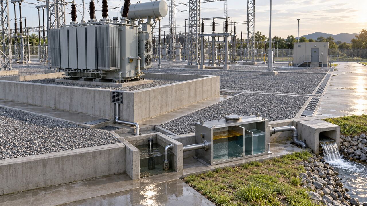
substations and related equipment, with engineering support from design interface through commissioning. Our engineering team will review the requirements and respond to project inquiries within 24 hours.
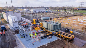
Evaluate transformer suppliers before tendering with an EPC checklist covering design, manufacturing, quality records, testing and site support.
View details
Build an auditable transformer commissioning punch list with risk classes, accountable owners, closure evidence, temporary controls and an EPC energization release gate.
View details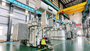
Plan a controlled transformer oil filling procedure for EPC projects, covering vacuum, oil quality, circulation, sampling, leak checks and handover.
View details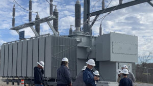
After years of working on-site with EPC projects, I have realized one critical truth: although transformers seem to be standard electrical equipment, every actual project requires customized support. Tiny differences in design parameters, dimensio...
View details