 zishengelectric




Project Partners
Phone/WhatsApp: 8619131285373
Email: info@zishengtransformer.com
Factory Headquarters: No. 118, Jingyi Street, Economic Development Zone.
Search productSearch post
Project Partners
Phone/WhatsApp: 8619131285373
Email: info@zishengtransformer.com
Factory Headquarters: No. 118, Jingyi Street, Economic Development Zone.
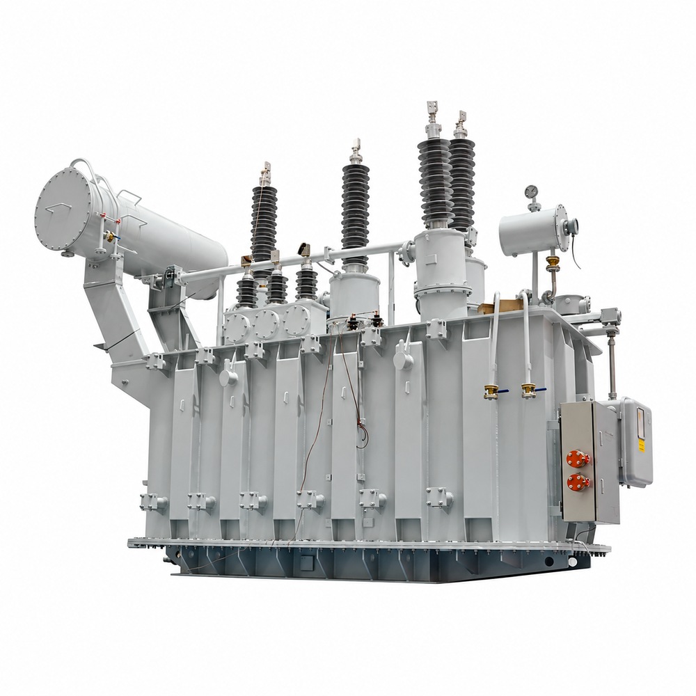
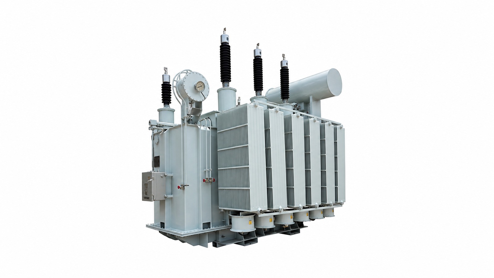
The 66kV / 69kV Power Transformer is a high-voltage transformer designed for power transmission, utility substations, industrial power systems and renewable energy applications. It provides voltage conversion between high-voltage networks and medium-voltage distribution systems.
The transformer combines a silicon steel core, insulated windings and an oil-filled tank. Electrical, thermal and mechanical requirements are coordinated with the project duty and approved technical specification.
The grain-oriented silicon steel core forms the magnetic circuit. Copper or aluminum windings, insulated leads, clamping and bracing are selected for the specified losses, temperature rise and short-circuit duty. Oil-paper insulation provides dielectric separation and transfers heat to the cooling surfaces. Material grades and final construction follow the approved design.
High- and medium-voltage bushings provide the external winding connections. Radiators transfer heat from the oil to ambient air. ONAN means Oil Natural Air Natural; ONAF means Oil Natural Air Forced and uses fans. Agree the rating at each cooling stage and the fan supply and control logic. ONAF does not create an unrestricted overload allowance.
The tank arrangement, conservator, tap changer, oil-level indication, temperature instruments, pressure-relief device and current transformers follow the agreed accessory schedule. A Buchholz relay applies to suitable conservator arrangements. Online monitoring and additional sensors are optional unless included in the order.
A 66kV transformer and a 69kV transformer are separate nominal-voltage options. Tap adjustment alone does not establish interchangeability. Review maximum system voltage, insulation coordination, terminal clearances, grounding and the utility specification before selecting the design.
| RFQ information | Why it matters |
|---|---|
| Rated MVA, load profile and power factor | Define continuous demand, starting duty, overload duration and expansion or contingency requirements. |
| HV/MV voltage, frequency and single-line diagram | Confirm every winding rating, the highest voltage for equipment and the actual step-up or step-down duty. |
| Insulation and grounding | Specify impulse and AC withstand levels, neutral arrangement and site pollution requirements. |
| Fault duty and parallel operation | Provide available fault current, clearing time and existing ratio, vector group, impedance and tap data. |
| Voltage regulation | Select OLTC or off-circuit taps; agree range, step size, drive supply and local/remote control. |
| Site and layout | Provide ambient temperatures, altitude, corrosion exposure, terminal orientation, clearances and foundation limits. |
| Acceptance and delivery | State contractual standards and editions, witness points, document requirements and transport restrictions. |
The intake duty combines continuous factory demand with intermittent motor starting and changing feeder loads. The engineering requirement is to supply the 11kV distribution bus from a 66kV utility connection while keeping voltage regulation, fault duty and future expansion within the approved limits.
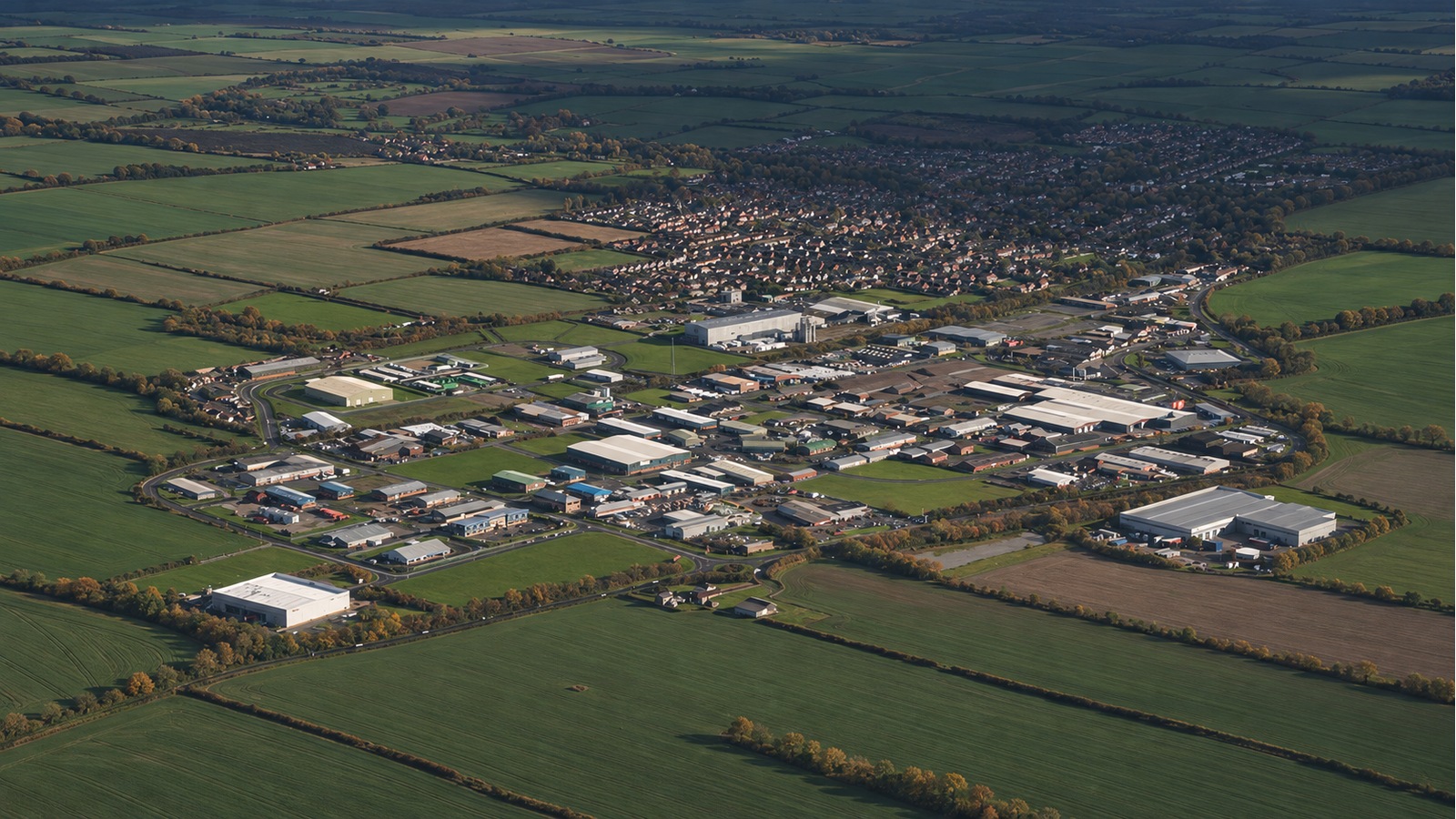
Selection starts with the diversified load schedule rather than adding installed motor nameplates. Convert demand from kW to kVA using the agreed power factor, then assess starting events and the required contingency duty separately. The MVA rating is finalized after the load-flow, motor-starting and short-circuit studies; no fixed capacity is inferred from the voltage ratio.
| Project interface | Engineering and acceptance requirement |
|---|---|
| Voltage conversion | 66/11kV, with frequency, insulation levels and neutral arrangement confirmed by the utility. |
| Load characteristics | Production feeders, pumps, ventilation and other motor loads; assess the largest starting event and nonlinear loads. |
| Configuration | Three-phase oil-immersed design; ONAN/ONAF stage ratings, winding material and OLTC or off-circuit taps to the approved schedule. |
| Site restrictions | Coordinate bushing orientation, cable routes, radiator access, oil containment and the heavy-haul path to the foundation. |
| Key engineering issue | Balance starting voltage drop, impedance, fault current and voltage regulation; check parallel compatibility if an existing unit remains. |
| Acceptance | Approve drawings and the ITP; review serial-number test reports and complete site phasing, earthing and protection checks before energization. |
The procurement package should define transformer supply, utility interfaces, civil works, protection settings and site assembly responsibilities. Any requested outage or staged cutover must be reflected in the installation sequence and acceptance plan.
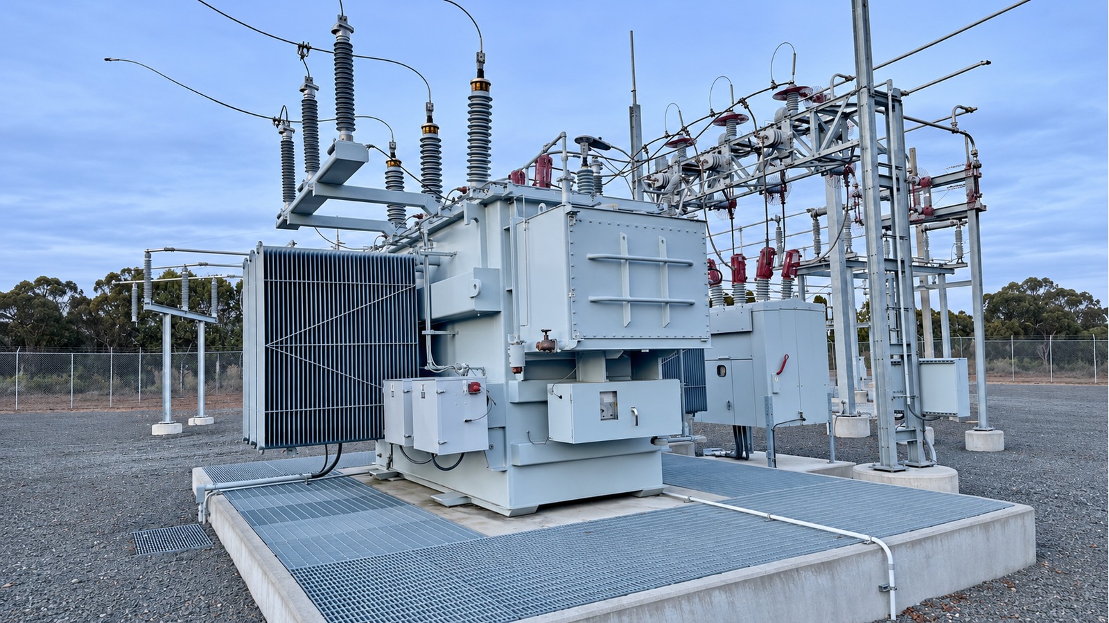
The transformer connects a 13.8kV collector system to a 69kV grid. The duty includes changing generation output and reactive-power requirements at the point of connection. Selection uses the complete operating envelope, including any permitted reverse power, rather than the plant's MW label alone.
| Project interface | Engineering and acceptance requirement |
|---|---|
| Voltage conversion | 69/13.8kV, subject to the grid connection agreement and approved winding arrangement. |
| Load characteristics | Variable export, reactive-power demand and inverter-related harmonics; account for any separately specified storage charging duty. |
| Rating and cooling | Establish MVA from active and reactive duty, site temperature and cooling-stage requirements. Do not equate MW directly with MVA. |
| Voltage control | Coordinate tap range and OLTC control, where specified, with plant voltage regulation and the grid operator. |
| Site restrictions | Review access, terminal clearances, earthing, oil containment and separation from adjacent switchgear. |
| Key engineering issue | Verify harmonic heating, fault duty, grounding and protection for every permitted switching and power-flow state. |
| Acceptance | Close the FAT dossier, tap/ratio schedule, accessory interfaces and site test records; demonstrate plant controls and protection under the approved commissioning plan. |
Confirm which tests belong to the transformer factory scope and which require the assembled plant at site. The transformer report does not by itself establish compliance of the complete generating facility with the grid connection agreement.
Coordinate the package with our transformer site acceptance checklist and OLTC control interface guide.
For a lower-voltage network, compare the 35kV 46kV Power Transformer. Select the voltage class from the utility connection requirements; it is not a substitute for a 66kV or 69kV design.
Listed range and configuration options are subject to the approved project datasheet. They are not one fixed transformer configuration.
| Rated Power | 5,000–400,000 kVA |
| Rated Primary Voltage | 69kV 66kV 63kV or others |
| Secondary Voltage | 33kV
13.8kV 11kV Customized |
| Frequency | 50 / 60 Hz |
| Vector Group | Dyn11, YNd1, Dyn1, YNd11 or others |
| Winding Material | Aluminum/Copper |
| Efficiency | As IEEE, CAS Std or Customized |
| Impedance Voltage | As IEC |
| Altitude | ≤1,000m or Customized |
| Enclosure material | Mild Steel |
| HV Bushing |
| LV Bushing |
| OLTC/NLTC |
| Lifting hook for complete transformer |
| Name plate |
| Oil temperature |
| Winding temperature |
| Radiators |
| Oil level |
| Pressure relief valve |
| CT |
Confirm the meaning of the existing “CAS” reference and the specific efficiency and impedance requirements before contract approval. Standards and editions, guaranteed losses, insulation levels, tap range, dimensions and masses must be stated in the order documents.
The listed bushings, tap changer, lifting provisions, temperature and oil-level devices, radiators, pressure-relief equipment and current transformers are configuration items. Confirm quantities, ratings and supply boundaries; OLTC and off-circuit tapping are alternatives, not an instruction to supply both.
| RFQ information | Why it matters |
|---|---|
| Rated MVA, load profile and power factor | Define continuous demand, starting duty, overload duration and expansion or contingency requirements. |
| HV/MV voltage, frequency and single-line diagram | Confirm every winding rating, the highest voltage for equipment and the actual step-up or step-down duty. |
| Insulation and grounding | Specify impulse and AC withstand levels, neutral arrangement and site pollution requirements. |
| Fault duty and parallel operation | Provide available fault current, clearing time and existing ratio, vector group, impedance and tap data. |
| Voltage regulation | Select OLTC or off-circuit taps; agree range, step size, drive supply and local/remote control. |
| Site and layout | Provide ambient temperatures, altitude, corrosion exposure, terminal orientation, clearances and foundation limits. |
| Acceptance and delivery | State contractual standards and editions, witness points, document requirements and transport restrictions. |
Options require an agreed engineering review. Do not assume that a conservator, OLTC, online monitor, fan stage or a particular CT arrangement is included unless listed in the quotation and purchase specification.
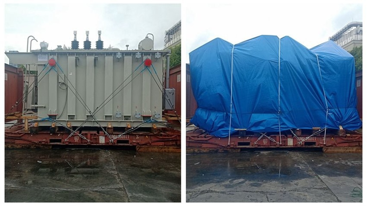
Plan delivery around the approved shipping dimensions, transport mass, centre of gravity, route survey and foundation access. The main tank is secured to a suitable heavy-haul platform or engineered transport base. A complete wooden crate or a standard pallet must not be assumed for the assembled transformer.
Whether bushings, conservator, radiators or cooler banks travel installed or separately depends on route clearance and the approved transport design. Protect machined flanges and openings, cap disconnected pipes and preserve the tank using the specified oil or dry-gas shipping condition. Crates or purpose-designed supports protect detached accessories; identify each package against the packing list.
Use only designated lifting, jacking, skidding and tie-down points. The lifting plan must account for the actual transport condition and attached equipment. Do not lift by bushings, conservator supports or radiator headers unless an approved drawing specifically permits it.
At arrival, compare serial numbers and packages with the dispatch records. Inspect restraints, covers, impact indicators where fitted, oil leaks, pressure or preservation status, bushings, flange seals and loose accessories. Photograph damage, record discrepancies and obtain an engineering disposition before assembly or energization. Site assembly, oil processing, electrical checks and protection commissioning follow the manufacturer-approved instructions and site acceptance plan.
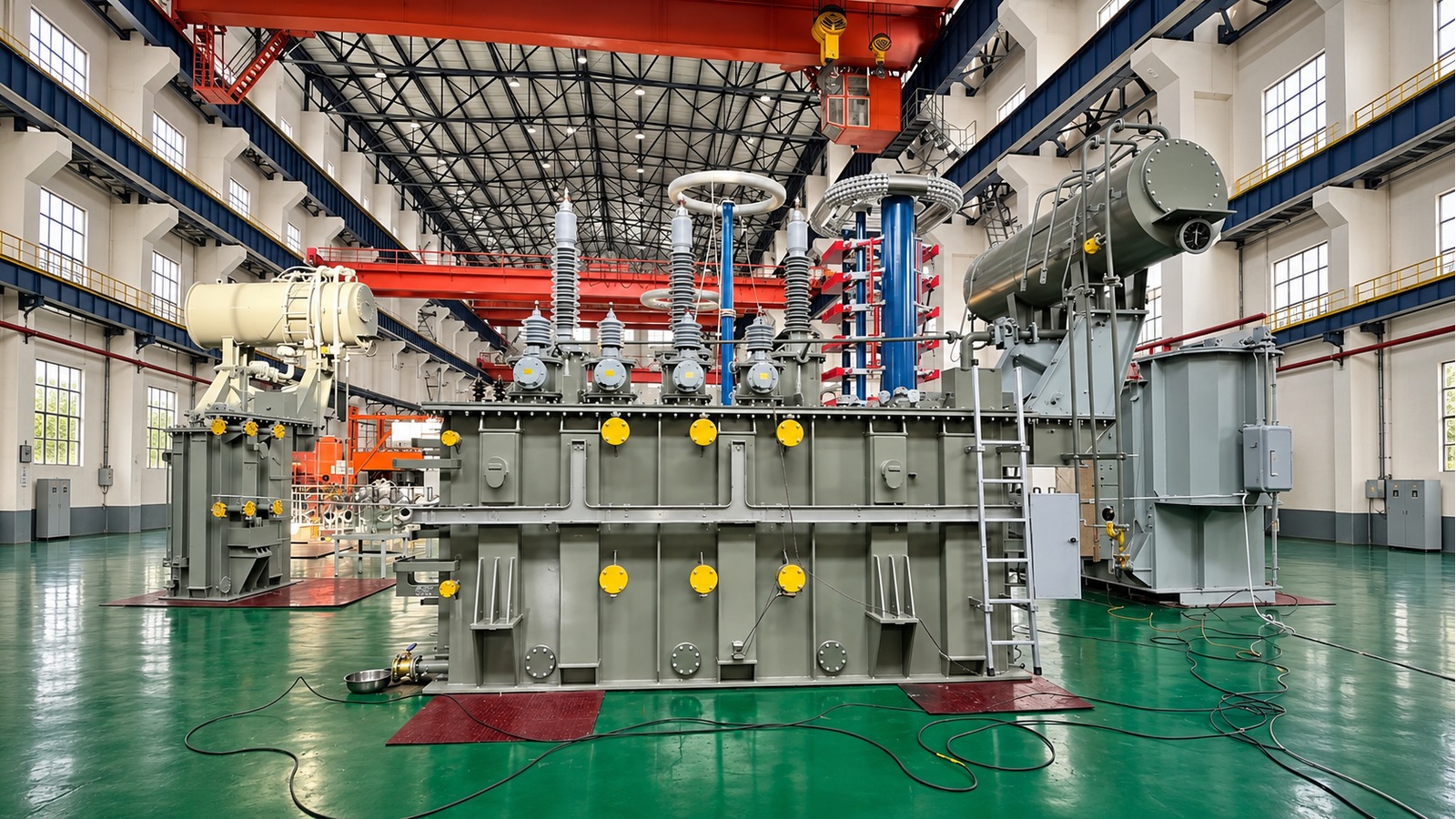
Core cutting and stacking, winding manufacture, insulation assembly, drying and oil treatment affect magnetic, dielectric and mechanical performance. Review material records, winding dimensions, insulation build, lead support and assembly cleanliness against the approved manufacturing plan.
Keep drawing revisions, component identification and inspection records linked to the transformer serial number. Drying method, oil filling procedure and any site oil-treatment requirements must follow the approved design and work instructions.
Agree the standard family, applicable parts and editions in the purchase specification. IEC 60076-1 — Power transformers, Part 1: General addresses general transformer requirements. IEEE C57.12.00 addresses general requirements for liquid-immersed distribution, power and regulating transformers. National adoptions or other standards apply only where specified and technically agreed. A reference to a standard is not a product certification.
The inspection plan should cover nameplate and drawing checks, external condition, fittings, oil-tightness, wiring continuity, tap operation and the functions of supplied alarms, cooling controls and protective accessories. These checks support manufacturing quality control; they do not replace electrical tests.
Define the routine test schedule using the applicable standard, transformer category and contract. It normally addresses winding resistance, ratio and phase displacement, no-load loss and current, and load loss and short-circuit impedance. The required dielectric test sequence depends on the equipment voltage, insulation arrangement and agreed standard.
Lightning impulse, induced-voltage testing with or without partial-discharge measurement, temperature-rise, sound-level and other tests must be classified and scheduled on that basis. Some may be mandatory for the selected transformer category; others require an agreed type-test or special-test scope. Short-circuit withstand evidence may involve an agreed calculation review or relevant test evidence; a destructive short-circuit test is not implied for every supplied unit.
Factory Acceptance Testing (FAT) uses the approved Inspection and Test Plan (ITP), test procedures and witness or hold points. Reports should identify the serial number, ratings, drawing revisions, test date, method, calibrated instrument references, measured values, corrections where applicable and acceptance criteria. Record deviations, corrective action and the release decision before dispatch.
Agree the final dossier: approved datasheet and general arrangement, nameplate drawing, wiring and terminal diagrams, accessory list, routine test reports, applicable type or special-test evidence, oil records, operation and maintenance instructions, packing list and transport drawings.
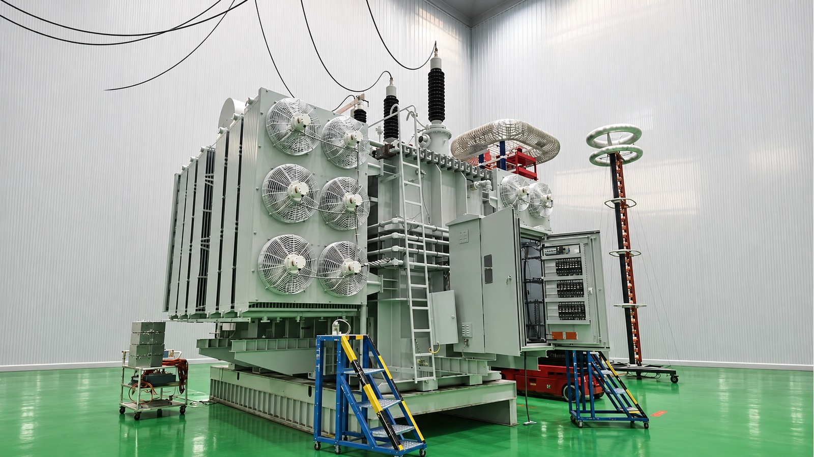
Step-down supply from a 66kV or 69kV network to regional medium-voltage feeders, including the upstream supply for major water, transport and public-facility networks. Review demand diversity, redundancy, bus switching, neutral grounding and utility protection interfaces. Downstream distribution equipment remains a separate design responsibility.
Main intake supply for industrial estates, manufacturing, mineral processing and oil-and-gas support systems. Assess large motor starting, continuous process duty, harmonics, dust or corrosion exposure and maintenance access. A conventional network transformer is not automatically a furnace, rectifier or hazardous-area transformer.
Step-up or interconnection duty for solar, wind and other generation projects, with storage interfaces where specified. Coordinate the collector voltage, export and import duties, reactive capability, harmonic study, tap control and point-of-connection requirements.
It transfers power between a 66kV or 69kV network and the specified medium-voltage system, or connects generation to the grid. The winding arrangement and MVA rating follow the single-line diagram and project studies.
Not automatically. Confirm rated and maximum system voltage, insulation levels, tap range, grounding, clearances and utility requirements. A tap position alone is not evidence that one unit is suitable for both networks.
The existing range is 5,000–400,000 kVA, subject to factory confirmation for the requested design. Listed HV options are 69kV, 66kV and 63kV or others; secondary options are 33kV, 13.8kV and 11kV or customized. Existing ratio examples also include 66/10.5kV and 69/34.5kV; confirm each ordered winding rating.
The existing page lists ONAN and ONAF, with copper or aluminum windings. Agree each cooling-stage rating, ambient conditions, fan control and auxiliary supply. Winding material must be declared for each winding in the approved datasheet.
An on-load tap changer (OLTC) supports tap changes while energized within its specified duty. Off-circuit tapping requires the transformer to be de-energized and made safe. Select the arrangement, range and step size from the voltage-regulation study and operating philosophy.
Provide the existing transformer ratio and tap data, vector group, phase sequence, impedance and rating. Review load sharing, circulating current, neutral arrangement and protection; identical nominal voltages do not establish compatibility.
Use the agreed standard and ITP to establish routine, type and special tests. Routine electrical tests normally cover resistance, ratio/phase displacement, losses, no-load current and impedance, together with the applicable dielectric schedule. Temperature-rise, impulse, partial-discharge and other requirements depend on the transformer category and contract; request the approved test list.
Match the serial number and ratings across the nameplate, drawings, test reports and packing list. Reports should include test methods, measured results, acceptance limits, instrument references and disposition of deviations. Witness arrangements and document release requirements are agreed before testing.
Use an engineered transport base, restraints and heavy-haul plan matched to the approved shipping mass and envelope. Detached accessories need protective packaging. On receipt, inspect preservation status, leaks, bushings, seals and package completeness before authorized assembly and site testing.
The existing page mentions 25–30 years or longer as a service-life reference. Actual life depends on thermal duty, insulation condition, installation, maintenance and fault exposure; it is not a warranty. The earlier 99.2–99.4% full-load efficiency statement requires confirmation of rating, power factor, temperature and test basis before it is used as a guarantee.
66kV 69kV Power Transformer