 zishengelectric



news
News Center
Providing high-quality power to the world
Search productSearch post
news
Providing high-quality power to the world
Transformer impedance tolerance is a procurement decision that connects the supplier’s guaranteed design with the EPC contractor’s network study. A bid stating “6% impedance” leaves an important question unanswered: which measured values can the factory deliver, and will every accepted value remain suitable for the intended installation? Resolving that question before purchase can prevent late changes to switchgear, operating restrictions or parallel loading plans.
This guide focuses on specifying and evaluating the acceptable range, rather than selecting a generic impedance value. It provides a practical method for comparing offers, controlling study assumptions and reviewing factory acceptance test results. The numerical examples are illustrative engineering calculations, not guaranteed Zisheng product ratings or a substitute for a project-specific system study.
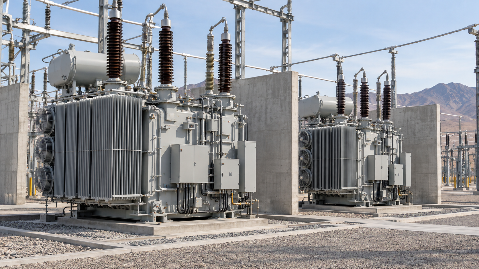
A guaranteed impedance is a reference value under defined conditions. Its tolerance determines the permitted departure from that value. The purchase specification should identify the winding pair, rated power base, frequency, reference temperature and tap position alongside the percentage. Without those details, two apparently identical offers may describe different test conditions.
Do not treat a percentage tolerance as an absolute number of percentage points. For a hypothetical guarantee of 6.0% with an agreed relative tolerance of ±10%, the permitted interval is 5.4% to 6.6%. It is not −4% to 16%. This arithmetic example does not establish a universal standard tolerance: the applicable limit depends on the transformer arrangement, tap and contractual standard.
Require the supplier to identify the governing standard and edition, the applicable tolerance provision and any proposed deviation. If the project needs a narrower interval, state its actual upper and lower endpoints. Ask the manufacturer to confirm feasibility and commercial consequences before award. Avoid adding a tight guarantee after the design has already been released.
For multi-winding equipment, define each required winding-pair impedance and its associated base. For transformers with taps, identify whether limits apply at the principal tap, specified extreme taps or an agreed operating range. One nominal-tap value cannot represent every operating condition.
The EPC study engineer should translate network constraints into an acceptable impedance envelope. The manufacturer then confirms whether its proposed design and production tolerance fit inside that envelope. This creates two distinct checks: compliance with the purchase guarantee and suitability for the connected system. Passing one does not automatically demonstrate the other.
| Boundary to establish | Project information needed | Procurement decision |
|---|---|---|
| Lower impedance limit | Maximum source strength, operating topology and equipment fault-duty limits | Confirm the lowest accepted impedance is included in the maximum fault study |
| Upper impedance limit | Load profile, power factor, voltage requirements and motor-starting cases | Confirm voltage performance at the highest accepted impedance |
| Parallel-unit mismatch | Existing unit test data, ratings, ratio, taps and connecting impedances | Set a compatible loading plan and any matching requirement |
| Tap-dependent envelope | Normal and contingency tap positions, regulation strategy | Request agreed tap-specific data and limits |
| Acceptance evidence | Contract guarantee, test method and study revision | Define who accepts the measured value and closes deviations |
These boundaries should appear in the technical bid evaluation, not only in an engineer’s calculation file. Record the document reference and revision behind each limit. If a study is preliminary, label it accordingly and define the date by which the design must be frozen. A supplier cannot assess an unspecified future network upgrade.
For a simplified three-phase transformer-terminal calculation with negligible upstream source impedance, rated secondary current is In = S / (√3 × V), and the symmetrical fault-current estimate is Isc ≈ In / zpu. Use VA, volts and per-unit impedance consistently. Schneider Electric’s Electrical Installation Guide describes this screening approach and its limitations.
Consider an illustrative 2,000 kVA, 400 V transformer. Rated current is approximately 2,887 A. Applying the hypothetical 5.4–6.6% interval gives the following results, holding voltage and all other assumptions constant.
| Impedance case | Calculation | Terminal fault-current estimate |
|---|---|---|
| Lower endpoint: 5.4% | 2,887 / 0.054 | 53.5 kA |
| Guaranteed value: 6.0% | 2,887 / 0.060 | 48.1 kA |
| Upper endpoint: 6.6% | 2,887 / 0.066 | 43.7 kA |
The difference is material when equipment selection is close to a duty limit. However, this table is not a final switchgear selection calculation. The complete study must include source impedance, voltage factors, cables or busduct, other connected sources and the relevant fault types. Breaking capacity, making duty and short-time withstand require their own applicable checks.
Record whether bus couplers are normally open or closed and which parallel configurations are actually permitted. A future tie closure can invalidate a study based only on separate transformer operation. Link this review to the project’s cable restraint and installation acceptance evidence, because associated fault-duty assumptions must remain consistent.

A higher impedance generally increases the transformer’s contribution to voltage drop for a given lagging load condition. The actual voltage result depends on the resistive and reactive components, loading and power factor. Request the data needed for the agreed study rather than substituting the impedance magnitude for every calculation input.
For an industrial project, separate steady production load from large motor starting and contingency operation. Identify the minimum supply voltage, long feeder runs, sensitive loads and permitted voltage excursions. Check these cases at the upper accepted transformer impedance and at relevant taps. A calculation at nominal load alone may miss the limiting operating condition.
Do not resolve every voltage concern by requesting a lower impedance. That change can increase fault duty and alter protection coordination. Return both boundaries to the study owner and obtain a coordinated revision. The purchasing team should receive one reconciled requirement instead of contradictory comments from separate disciplines.
Two units sharing the same nominal impedance may have different measured values within their permitted tolerances. Successful parallel operation also depends on compatible phase displacement, voltage ratio, tap behavior and connection arrangements. Schneider Electric’s parallel transformer guidance explains why unequal relative impedances can reduce usable combined capacity.
Assume two equal-rated transformers have identical no-load voltage ratios, equal impedance angles and negligible connection-impedance differences. If their measured impedances are 5.4% and 6.6% on the same base, the lower-impedance unit carries approximately 6.6 / (5.4 + 6.6) = 55% of total load. The other carries approximately 45%. At a total demand equal to their combined nameplate rating, that becomes approximately 110% and 90% of individual ratings.
This example illustrates unequal load sharing; it does not by itself demonstrate a no-load circulating current. Voltage-ratio mismatch is a separate concern. Real studies should use complex impedances, actual ratios, taps and connecting circuits. Do not use the simplified split as an operating authorization.
When replacing one transformer in an existing pair, request the retained unit’s factory report and nameplate data before tender evaluation. If dependable measured data are unavailable, treat compatibility as an open engineering action. Do not promise full combined output on the basis of matching catalogue percentages alone.

An effective bid comparison puts every supplier on the same basis. Create a row for each guaranteed value, each permitted endpoint and each test condition. Distinguish “complies,” “exception proposed” and “information missing.” Silence should not be converted into acceptance, especially where a supplier’s standard tolerance differs from the project envelope.
| Bid-review item | Evidence to request | Decision before award |
|---|---|---|
| Nominal guarantee | Signed technical schedule with winding pair and base | Confirm comparability with study inputs |
| Tolerance endpoints | Numeric limits and contractual reference | Accept, negotiate or reject the stated interval |
| Tap coverage | Agreed tap values or impedance characteristic | Close gaps in the intended operating range |
| Existing parallel partner | Retained-unit records and proposed compatibility review | Approve the loading assumptions or document restrictions |
| Manufacturing deviation | Notification process and decision responsibilities | Define the hold point before shipment |
Ask for a clear price and delivery impact if tighter limits require a revised design. Evaluate that impact against the cost of changing downstream equipment or restricting operation. The cheapest transformer offer may not produce the lowest installed-project cost, but the comparison should use documented consequences rather than assumed penalties.
The factory report should allow the reviewer to identify the tested unit, winding pair, tap, rating base, frequency, reference temperature and reported impedance. Compare the normalized result with the agreed guarantee and endpoints. Keep the original report alongside any calculation sheet used to reconcile bases or conditions.
Use three release outcomes. If the result meets both the contract and the approved system envelope, record acceptance. If it meets the contract but challenges the study margin, hold the engineering release while the study owner evaluates the consequence. If it falls outside the contract, raise a formal nonconformance and obtain an authorized disposition; do not silently widen the accepted tolerance.
A concession, where contractually permitted, should identify the affected serial number, revised study result, operational consequences and approving parties. Updating a spreadsheet value without a traceable decision is insufficient. Where a revision affects protection or control assumptions, reconcile the EPC protection and control interface matrix before final release.
Store the final measured value in the as-built equipment record and link it to the approved network model. This gives future expansion or replacement teams a reliable starting point. Include the accepted report in the transformer delivery release package, with any outstanding actions assigned to named project roles.

No. It may improve some voltage-performance cases while increasing available fault current. The acceptable value must satisfy both ends of the system envelope. Procurement should therefore specify coordinated limits instead of a one-direction preference.
The guaranteed value alone is insufficient. Review measured impedance, ratio, vector relationship, taps, connecting circuits and the required loading plan. Compatibility should be confirmed for the intended operating modes by the responsible engineer.
Check the tap coverage required by the contract and operating study. Where the system depends on performance at other taps, state the data and acceptance requirements before award. Do not assume that one measured value covers the whole range.
Keep contractual compliance and system suitability separate. Request an updated study and an authorized release decision. Depending on the result, the project may need revised equipment selection, design changes or documented operating limits.
Provide capacity, HV/LV voltage, frequency, winding arrangement, tap range, guaranteed impedance and required endpoints. Add the project location, operating topology, source fault-level data, parallel-unit records, applicable standards and delivery schedule.
Send Zisheng Electric your transformer schedule and impedance acceptance requirements with the supporting network-study assumptions. Our enquiry review can establish the proposed supply scope, required technical submissions and points needing clarification before quotation. Include quantity, application and any retained transformer data so the discussion addresses your actual EPC procurement boundary.
Images are AI-generated engineering scene illustrations and do not document a specific factory test or completed customer project.
Compare VPI and VPE transformer offers by resin, processing, environmental duty and guaranteed performance. Learn which supplier evidence makes an EPC comparison useful.
View details
Understand transformer BIL, distinguish impulse withstand from operating voltage, and check the terminal, test basis and supplier evidence before approving an EPC datasheet.
View details
Review a dry-type transformer fan upgrade before ordering: confirm the approved rating, electrical capacity, room ventilation, failure response and handover evidence.
View details
Check a 60 Hz transformer offer for a 50 Hz project. Review voltage-to-frequency ratio, output voltage, capacity, auxiliaries and written manufacturer approval.
View details