zishengelectric




Project Partners
Phone/WhatsApp: 8619131285373
Email: info@zishengtransformer.com
Factory Headquarters: No. 118, Jingyi Street, Economic Development Zone.
Search productSearch post
Project Partners
Phone/WhatsApp: 8619131285373
Email: info@zishengtransformer.com
Factory Headquarters: No. 118, Jingyi Street, Economic Development Zone.
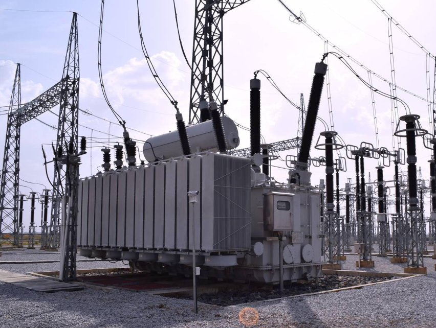
The 138kV / 140kV / 150kV Three-Phase Oil-Immersed Power Transformer is a high-voltage oil-immersed transformer designed for utility substations, power generation plants, industrial power networks, renewable energy projects, and large-scale transmission and distribution systems.
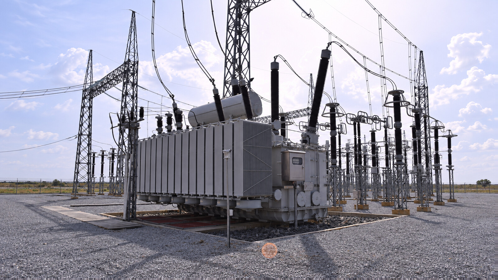
It is engineered to provide reliable voltage transformation between high-voltage transmission networks and medium- or low-voltage distribution systems. Depending on the project, the transformer can be configured as a step-up or step-down transformer with customized capacity, voltage ratio, vector group, impedance, cooling system, tap changer and protection system.
The HV winding is specified for 138kV, 140kV or 150kV. Select the MV/LV winding voltage from the project bus arrangement, with 11kV, 13.8kV, 33kV, 34.5kV or a customized voltage as applicable. Confirm the complete winding-voltage schedule in the approved datasheet.
Rated capacity can be designed from several MVA to tens or hundreds of MVA, depending on the application and grid requirements.
| Parameter | Typical Specification |
|---|---|
| Product Type | High Voltage Oil-Immersed Power Transformer |
| Rated Capacity | Customized, typically 10–200+ MVA |
| Primary Voltage | 138kV / 140kV / 150kV |
| Secondary Voltage | 11kV / 13.8kV / 33kV / 34.5kV / Customized |
| Frequency | 50Hz / 60Hz |
| Phase | Three Phase |
| Cooling Method | ONAN / ONAF / OFAF / OFWF |
| Winding Material | Copper / Aluminum |
| Tap Changer | OLTC / Off-Circuit Tap Changer |
| Vector Group | Dyn11 / YNd11 / YNyn0 / Customized |
| Neutral | Solid / Resistance / Reactance Grounded, as required |
| Insulation Medium | Mineral Oil / Ester Fluid |
| Oil Preservation | Conservator / Sealed Type |
| Core Material | High-Grade Grain-Oriented Electrical Steel |
| Frequency | 50 / 60Hz |
| Installation | Outdoor / Indoor |
| Insulation Level | According to system voltage and applicable standard |
| Standards | IEC 60076 Series / IEEE / ANSI or Customized |
| Accessories | Buchholz Relay, PRD, OTI, WTI, MOG, etc. |
| Monitoring | Optional Online Monitoring System |
Note: Final electrical parameters must be determined from the customer's technical specification, grid code, utility requirements and transformer design.
Designed for 138kV, 140kV and 150kV transmission and sub-transmission networks, with insulation systems engineered for high electrical stress and long-term reliability.
Optimized magnetic core and winding design reduces:
The winding structure is mechanically reinforced to withstand the electromagnetic forces generated during short-circuit conditions.
The insulation system is designed around:
Oil + Paper / Pressboard + Insulation Components + Controlled Electric Field Distribution
High-quality insulation materials and optimized field grading improve dielectric reliability.
Different cooling configurations can be selected according to transformer capacity and operating conditions:
ONAN → ONAF → OFAF / OFWF
An On-Load Tap Changer (OLTC) can be installed to regulate the output voltage while the transformer remains energized.
This is particularly useful for utility substations where grid voltage fluctuates during operation.
The core is manufactured from high-quality grain-oriented electrical steel.
Typical design features include:
The core is carefully clamped to maintain mechanical integrity during transportation and operation.
The HV winding is designed specifically for high-voltage electrical stress.
The design considers:
Depending on the capacity and voltage class, different winding structures can be selected.
The secondary winding can be configured for common substation voltages such as:
11kV • 13.8kV • 33kV • 34.5kV
Customized voltage ratios are also available.
The transformer tank is manufactured from high-strength steel and designed to withstand:
The tank can be subjected to leakage and pressure testing before shipment.
For 138kV / 140kV / 150kV power transformers, an OLTC can be provided for automatic voltage regulation.
Typical options include:
The actual tap range and number of positions are customized according to the grid specification.
The OLTC can be integrated with:
The cooling system is selected according to transformer capacity and project requirements.
Oil Natural Air Natural
Suitable for transformers where natural oil and air circulation can provide sufficient cooling.
Oil Natural Air Forced
Cooling fans increase heat dissipation and improve the transformer's load capability.
Oil Forced Air Forced
Oil pumps and cooling fans are used for larger-capacity transformers.
Oil Forced Water Forced
Suitable for specific high-capacity or special installation environments.
A complete 138kV / 140kV / 150kV transformer can be equipped with comprehensive protection and monitoring devices.
The 138kV / 140kV / 150kV transformer can be equipped with high-voltage condenser bushings suitable for the specified system voltage and insulation level.
Configuration can be customized according to:
For coastal, desert or heavily polluted environments, an increased creepage distance can be considered.
The transformer can use:
The oil insulation system is selected according to the project requirements and applicable standards.
Before filling, the insulating fluid can undergo appropriate treatment such as:
Filtration → Vacuum Treatment → Moisture Removal → Dielectric Strength Verification → Filling
The 138kV / 140kV / 150kV Three-Phase Oil-Immersed Power Transformer can be engineered according to EPC, utility and grid requirements.
Specify 138kV, 140kV or 150kV as the required HV winding rating. These are separate design options, not interchangeable nameplate ratings. The network nominal voltage, highest voltage for equipment, insulation coordination and MV/LV bus arrangement determine the final winding-voltage and dielectric requirements.
Confirm the MVA rating at each cooling stage, frequency, vector group, impedance, tap range, grounding and protection interfaces in the approved technical schedule.
Specify the transformer from the system study and load or generation profile. Nominal network voltage alone does not define the required insulation level, MVA rating or winding arrangement.
For renewable generation, include the required reactive-power operating range, harmonic data and grid-code duty. For motor-driven industrial loads, provide starting studies and voltage-dip limits. Confirm losses and impedance on the same rating and reference-temperature basis when comparing offers.
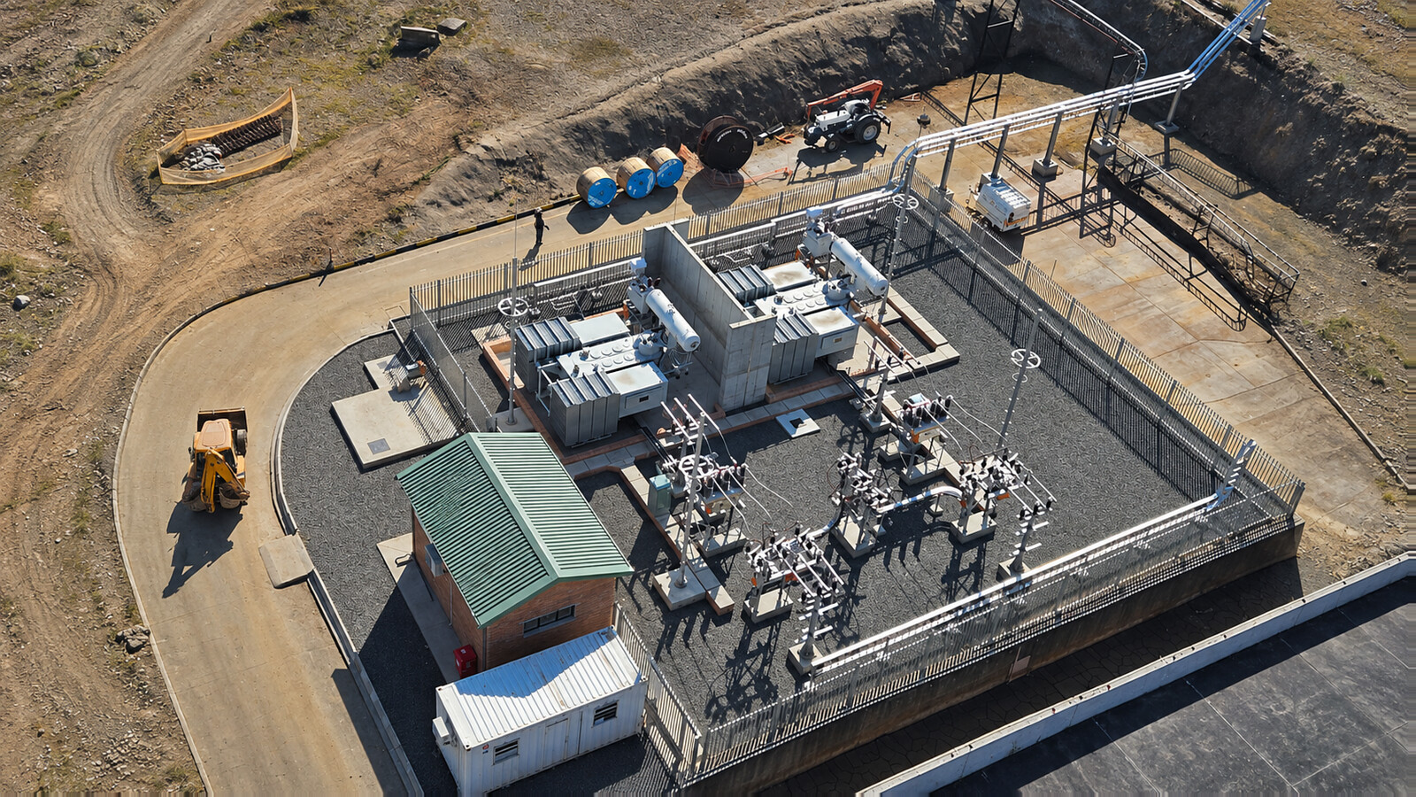
The mining substation supplies three-phase crushers, conveyors, water pumps and process auxiliaries. Large motor starts overlap with continuous process demand, so the transformer review uses the simultaneous kVA profile, starting method, available fault level and permitted voltage dip. The upgrade also needs to fit the existing bay and planned shutdown window.
| Engineering item | Case requirement |
|---|---|
| Transformer duty | Three-phase oil-immersed step-down service within the 138kV / 140kV / 150kV product range |
| Voltage interface | HV winding selected from 138kV, 140kV or 150kV; MV winding voltage, final ratings and terminal arrangement confirmed in the approved design |
| Rating and impedance | Selected from the load and starting studies; impedance checked against fault duty and voltage regulation |
| Site constraints | Existing foundation and bushing positions, access route, crane setup, pollution and maintenance clearances |
| Configuration | Project-approved winding arrangement, grounding, cooling stages and tap-control scope |
| Acceptance | Approved drawings, traceable test reports, control and protection interface checks, transport and arrival records |
Where the new unit operates in parallel with an existing transformer, the engineering review checks voltage ratio, vector group, polarity, tap positions and impedance characteristics before connection. Where units remain separate, the bus-transfer and protection design still needs review. The accessory and control schedules identify alarm, trip, cooling and SCADA interfaces for the site team.
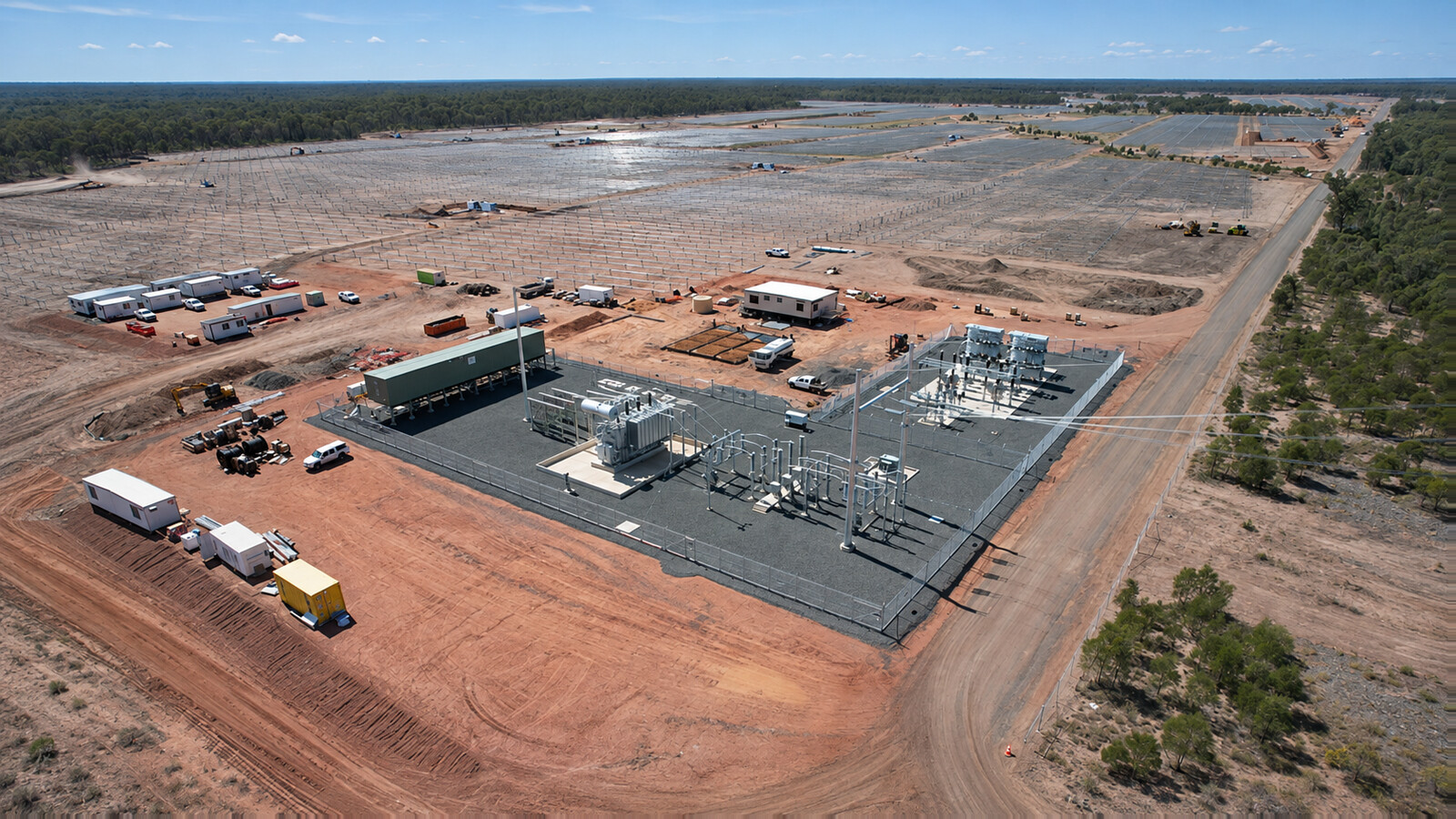
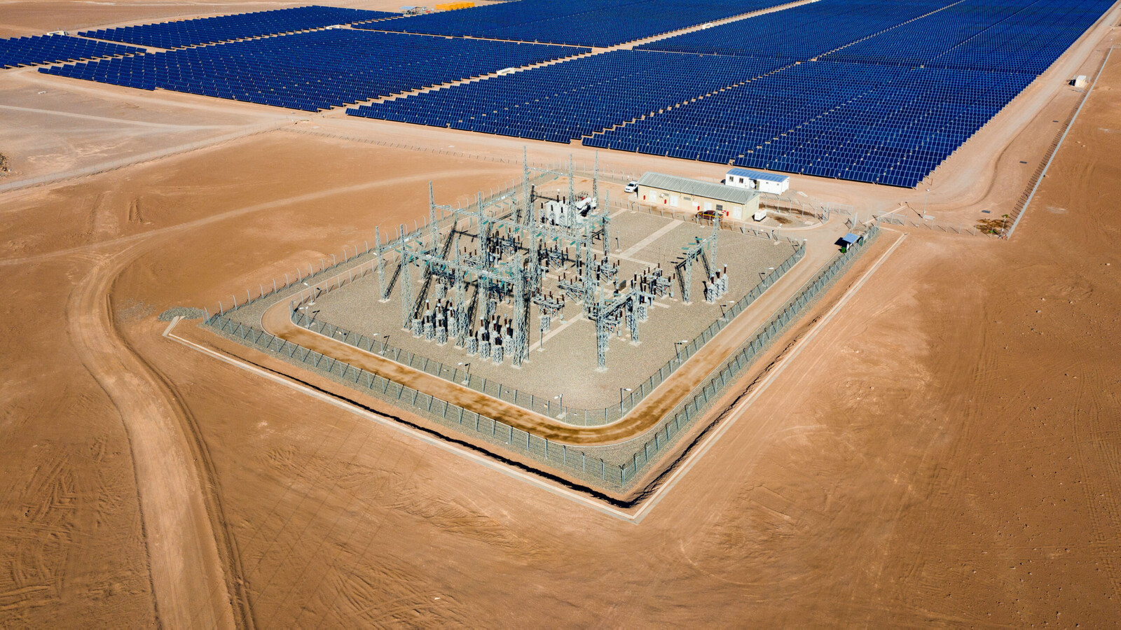
The solar plant exports three-phase power from its collection network to a 138kV grid connection. Selection uses the permitted active and reactive power envelope, auxiliary demand and harmonic study rather than the panel DC rating alone. Available substation land, terminal clearances and access for future radiator or bushing maintenance define the physical arrangement.
| Engineering item | Case requirement |
|---|---|
| Transformer duty | Three-phase oil-immersed grid step-up service |
| Grid interface | 138kV connection with utility-approved insulation and grounding |
| Capacity basis | MVA over the required active/reactive operating envelope and site temperature conditions |
| Electrical coordination | Collector voltage, vector group, harmonic duty, neutral arrangement and impedance confirmed by the connection study |
| Regulation and cooling | Agreed tap range, voltage-control responsibility, cooling ratings and auxiliary supply |
| Acceptance documents | Approved technical schedule, dielectric test plan, witnessed FAT records where specified, control drawings and shipping release |
The plant controller and tap regulator need an agreed operating philosophy to avoid conflicting voltage commands. The purchaser and manufacturer review protection CT requirements, neutral earthing, inrush and overfluxing considerations, and the effects of harmonic currents. Shipment release follows the approved inspection plan; site acceptance also verifies reassembled components, fluid condition and pre-energization checks.
Browse the oil-immersed transformer range, or compare the 110kV / 115kV power transformer for projects at a different network voltage. For procurement and handover, read our transformer inspection and test plan guide and transformer site acceptance checklist.
The 138kV / 140kV / 150kV Three-Phase Oil-Immersed Power Transformer is designed for high-voltage transmission and substation applications. The following specification provides a professional baseline for EPC, utility, industrial, and renewable-energy projects. Final values can be customized according to the approved technical specification.
| Item | Specification |
|---|---|
| Product Type | Oil-Immersed Power Transformer |
| Rated Capacity | 10–200+ MVA, Customized |
| Number of Phases | Three Phase |
| Rated Frequency | 50Hz / 60Hz |
| HV Rated Voltage | 138kV / 140kV / 150kV |
| MV/LV Rated Voltage | 11kV / 13.8kV / 33kV / 34.5kV / Customized |
| Voltage Ratio | HV: 138kV / 140kV / 150kV; MV/LV winding voltage according to the approved project datasheet. |
| Cooling Method | ONAN / ONAF / OFAF / OFWF |
| Tap Changer | OLTC / Off-Circuit Tap Changer |
| Tap Range | Typically ±10% / ±12.5% / ±15%, Customized |
| Vector Group | Dyn11 / YNd11 / YNyn0 / Customized |
| Winding Material | Copper / Aluminum |
| Insulation System | Oil-Paper Insulation |
| Insulating Medium | Mineral Oil / Ester Fluid |
| Core Material | Grain-Oriented Electrical Steel |
| Core Construction | Step-Lap / Mitred Core |
| Tank Type | Conservator / Sealed Type |
| Installation | Outdoor / Indoor |
| Temperature Rise | According to project specification |
| Impedance | Customized according to system requirements |
| Insulation Level | According to applicable standard and system voltage |
| Standards | IEC 60076 / IEEE / ANSI |
| Service Life | Designed for long-term continuous operation |
| Altitude | ≤1000m standard; higher altitude available |
| Ambient Temperature | Standard design; customized for special climates |
| HV winding option | MV/LV interface and acceptance basis |
|---|---|
| 138kV | Project-specified MV/LV voltage, winding arrangement, insulation level and tap schedule; final values confirmed in the approved design. |
| 140kV | Project-specified MV/LV voltage, winding arrangement, insulation level and tap schedule; final values confirmed in the approved design. |
| 150kV | Project-specified MV/LV voltage, winding arrangement, insulation level and tap schedule; final values confirmed in the approved design. |
The transformer can be equipped with:
For utility and EPC projects, the transformer can be configured with:
Online DGA Monitoring • Bushing Monitoring • OLTC Monitoring • Temperature Monitoring • Moisture Monitoring • RS485 / Modbus • IEC 61850 • SCADA Integration
Each transformer can be subjected to comprehensive factory testing, including:
Additional type tests, special tests, FAT and third-party inspection can be provided according to EPC or utility requirements.
The 138kV / 140kV / 150kV Three-Phase Oil-Immersed Power Transformer can be customized for:
MVA Capacity • Voltage Ratio • Frequency • Vector Group • Impedance • OLTC • Cooling • Insulation Level • Bushings • Protection • Monitoring • Enclosure • Climate • Installation Conditions
138kV / 140kV / 150kV | Custom MVA | OLTC | ONAN/ONAF | IEC / IEEE / ANSI | EPC & Utility Projects
The 138kV / 140kV / 150kV Three-Phase Oil-Immersed Power Transformer can be custom-engineered according to utility, EPC, grid, renewable energy, and industrial project requirements. Key electrical, mechanical, protection, monitoring, and environmental parameters can be configured to match the project specification.
Typical tap ranges can be configured according to the grid specification, such as ±10%, ±12.5% or ±15%.
The cooling configuration can be selected according to transformer capacity and operating conditions:
High-voltage bushings can be selected according to:
Optional systems include:
The transformer can be engineered for demanding operating conditions:
High Altitude • Tropical Climate • Desert Environment • Coastal Areas • High Humidity • Heavy Pollution • Dusty Sites • High Temperature • Seismic Conditions
Customized anti-corrosion coating and increased creepage distance can be provided where required.
For large EPC and utility projects, the transformer can be supplied according to approved project documentation, including:
Customized project documentation can include:
Custom MVA • Custom Voltage • OLTC • Custom Cooling • Custom Protection • Utility & EPC Engineering
Specify the transformer from the system study and load or generation profile. Nominal network voltage alone does not define the required insulation level, MVA rating or winding arrangement.
For renewable generation, include the required reactive-power operating range, harmonic data and grid-code duty. For motor-driven industrial loads, provide starting studies and voltage-dip limits. Confirm losses and impedance on the same rating and reference-temperature basis when comparing offers.
Transport planning uses the final main-unit shipping mass, center of gravity, packed dimensions, route survey and permitted handling loads. Select the trailer, rail arrangement, container or break-bulk method from those actual limits rather than assuming one shipping method for every rating.
The approved transport drawing identifies whether bushings, radiators, conservator, cooling equipment or other accessories travel separately. Protect and seal opened interfaces against moisture and contamination. The manufacturer specifies the shipping oil level or dry-gas preservation condition, pressure limits and storage checks; do not drain the unit or apply vacuum without the approved procedure.
Secure the main unit through the designated transport restraints. Where detached accessories require wooden crates or protective frames, provide fitted supports, moisture protection, package identification and suitable lifting points. Packing lists should match each crate to the transformer serial number and assembly drawing. Wood packaging must meet the destination's applicable phytosanitary requirements.
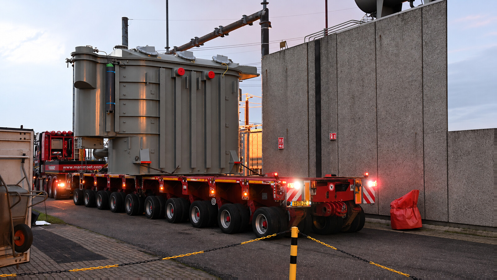
Use the approved lifting plan, rated slings and identified lifting or jacking points. Bushings, radiators, valves and pipework are not lifting points. Confirm crane reach, ground bearing capacity, trailer axle loads, bridge and turning limits, overhead clearances and unloading access. Fit shock or tilt recorders when specified and retain their identification and baseline records.
On arrival, inspect the main tank, seals, bushings, crates and supplied accessories for impact damage, leakage or water ingress. Check transport indicators, the specified preservation condition and all serial numbers before unloading or storage release. Record exceptions with photographs and notify the supplier and carrier promptly.
Reassembly, fluid processing, electrical checks and pre-energization acceptance follow the approved installation instructions and utility requirements. Review any agreed baseline measurements after transport and resolve abnormal results or damage before energization. Delivery documents should include the packing list, transport drawing, handling instructions, agreed factory reports and the records required by the contract.
The inspection plan links incoming materials, active-part assembly, tank fabrication, drying and filling, final tests and packing release to the approved transformer design.
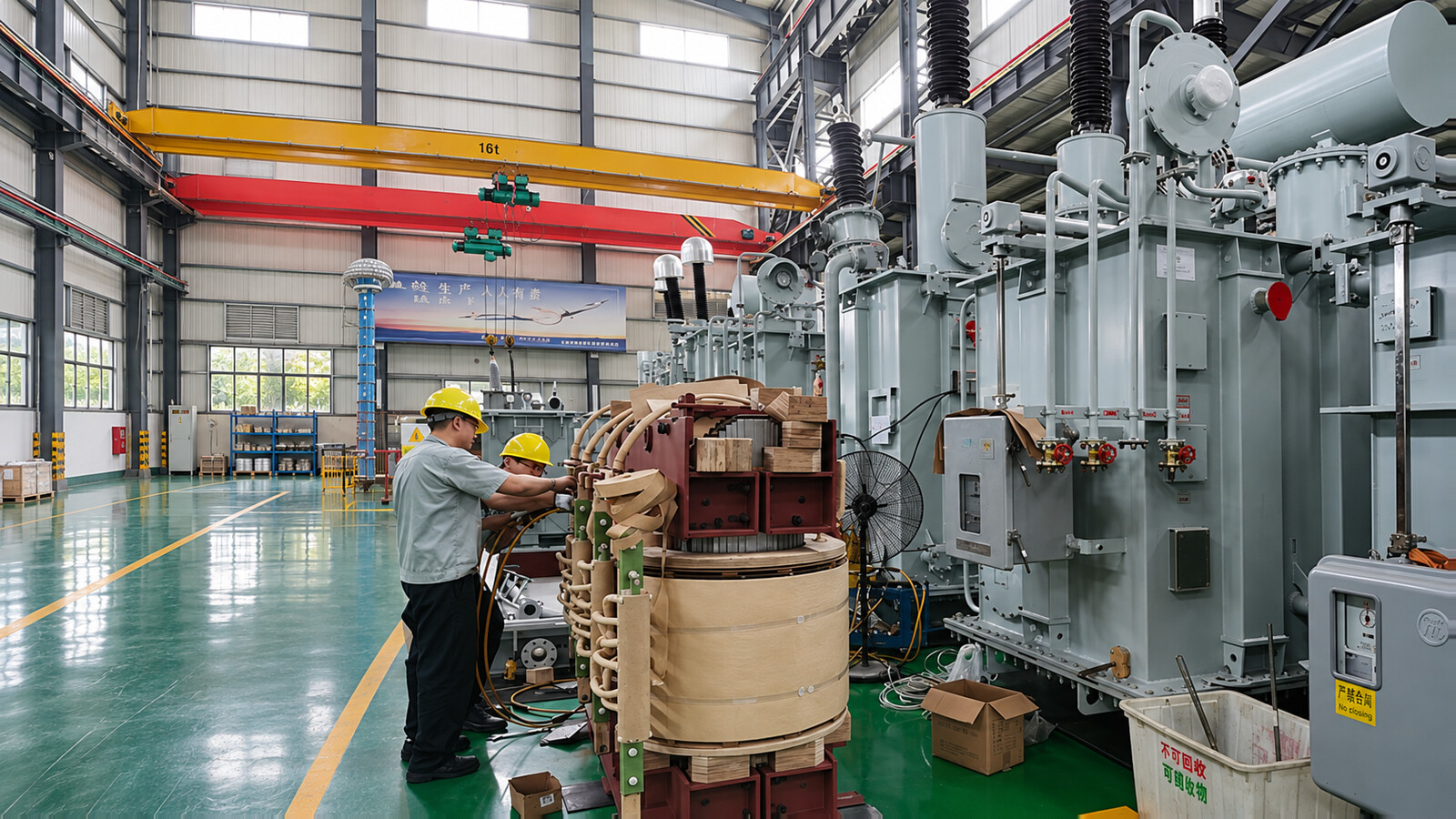
Customer or third-party witness points, notification periods and document-review hold points must be agreed before production. Inspection photographs support the records but do not replace measured test results or acceptance criteria.
Agree the governing standard and edition, inspection and test plan, test levels, acceptance limits and witness points before manufacture. IEC 60076-1 covers general power-transformer requirements; IEC 60076-3 addresses insulation levels and dielectric tests. These are technical standards, not product certifications.
| Item to define in the test plan | Purpose and acceptance record |
|---|---|
| Visual, dimensional and nameplate checks | Verify construction, terminal positions, accessories and identification against approved drawings. |
| Winding resistance | Check winding and connection consistency, with temperature and tap positions recorded. |
| Ratio and phase displacement | Verify the ordered voltage ratio, vector group and tap schedule. |
| No-load loss and excitation current | Assess magnetic-circuit performance under the specified voltage and frequency. |
| Load loss and short-circuit impedance | Verify contractual loss and impedance values on the agreed rating and reference-temperature basis. |
| Applicable dielectric tests | Assess insulation using the test sequence and levels assigned to each winding by the governing standard and design category. |
| Tank tightness, controls and accessories | Check the specified sealing procedure and operation of supplied cooling, tap changer, alarm and trip circuits. |
The standard and contract determine which checks are routine and which are type or special tests. Lightning or switching impulse tests, induced-voltage tests with partial-discharge measurement, temperature-rise tests, sound measurements, short-circuit withstand verification and other diagnostics must be assigned explicitly. Dielectric tests required by the applicable voltage category are not automatically optional. SFRA, oil analysis and other agreed diagnostic records may provide transport or commissioning baselines.
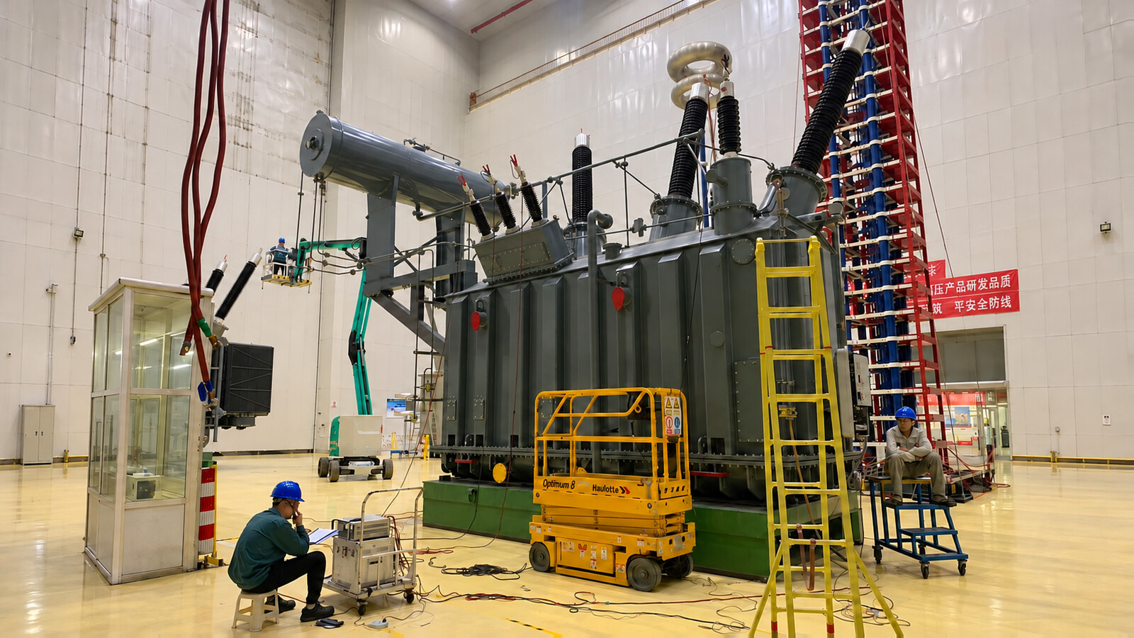
Test reports should identify the transformer serial number, approved ratings, methods, test conditions, measured values, acceptance limits and conclusions. Match the serial number across the nameplate, drawings, reports and packing list. A witnessed Factory Acceptance Test (FAT) uses the agreed inspection plan; it does not mean every possible type or special test is repeated for every unit.
Request the approved datasheet, general arrangement and transport drawings, connection diagram, bushing and tap-changer information, accessory schedule, control schematics, test reports, operating instructions and inspection-release documents. Close outstanding nonconformities and agreed witness points before shipment release.
Connect transmission or sub-transmission networks to the required substation bus. Selection considers normal and contingency loading, fault levels, neutral grounding, insulation coordination and compatibility with existing transformers.
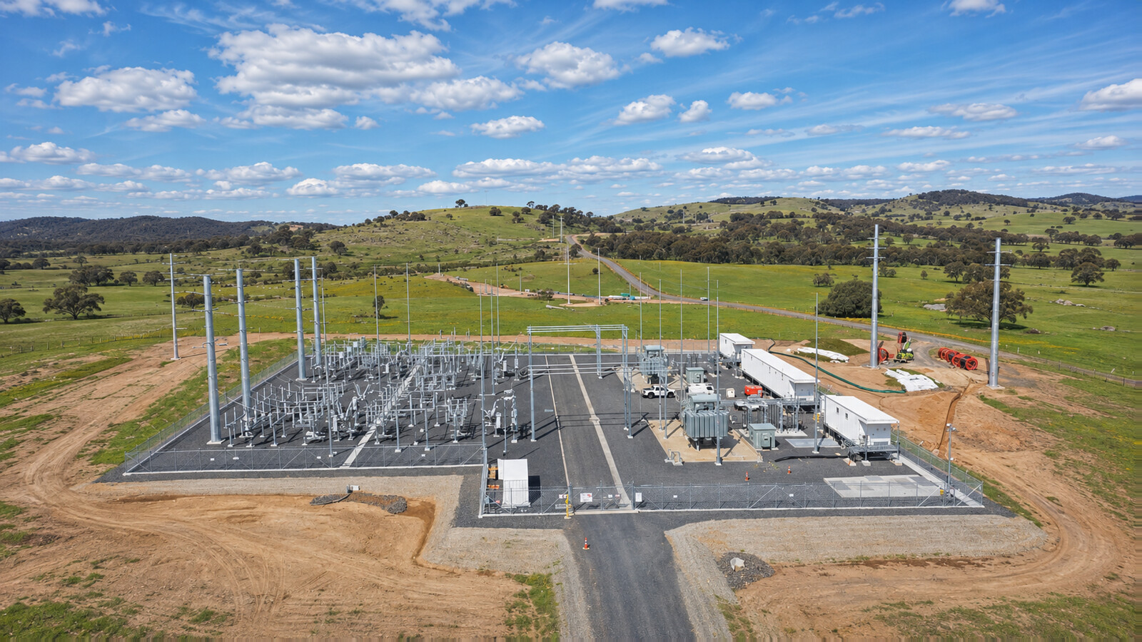
Connect the plant's medium-voltage collection system to the high-voltage grid. Review continuous MVA over the reactive-power operating range, inverter harmonics, tap-control strategy and the agreed grid-code duty.
Provide the interface between wind-farm collection circuits and the transmission connection. The design review covers variable generation, reactive-power duty, grounding, harmonics, low-temperature conditions where applicable and cooling auxiliaries.
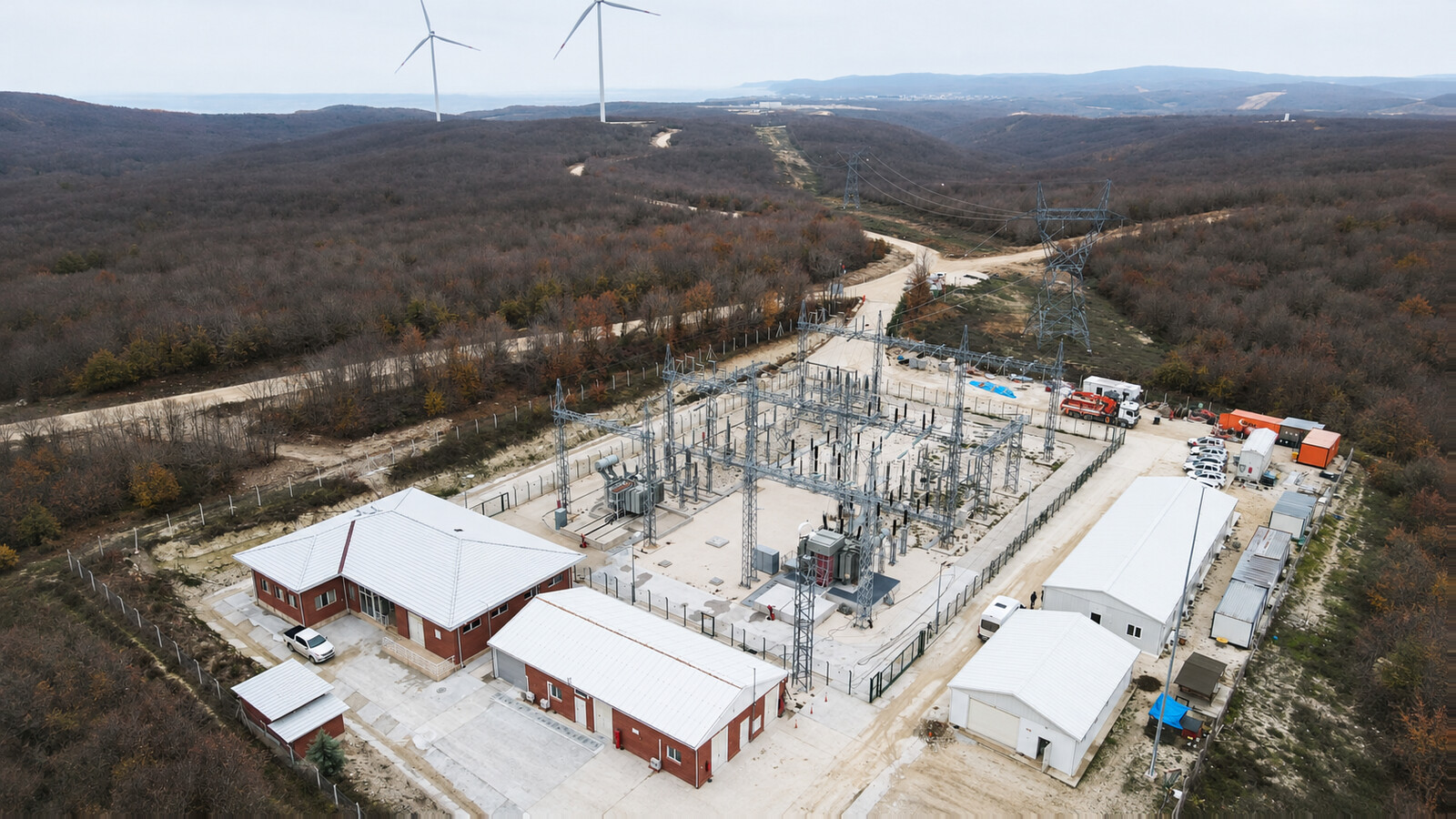
Supply internal distribution networks serving motor-driven processes and industrial auxiliaries. Motor starting, fluctuating demand, harmonic loads, pollution, site access and outage constraints inform the required transformer design.
Specify a 138kV, 140kV or 150kV HV winding rating for the ordered design. These are separate voltage options, not interchangeable nameplate ratings. Provide the nominal system voltage, highest voltage for equipment, grounding and required impulse and AC withstand levels for each winding and neutral.
Provide the simultaneous load or generation profile, power factor or reactive-power range, ambient conditions, cooling stages, contingency duty and growth requirement. For motor-driven loads, include starting studies and voltage-dip limits.
The listed ONAN, ONAF, OFAF and OFWF configurations are selected through engineering review. Confirm the rating at each cooling stage, auxiliary power and any cooling-water interfaces. Forced cooling is not included unless specified.
An OLTC is available where specified in the technical offer. Confirm the tapping winding, range, steps, current rating, drive supply, regulator and local/remote controls. An off-circuit tap changer requires isolation and de-energization.
Parallel operation requires review of ratio, vector group, polarity, tap positions, impedance characteristics and the network arrangement. Provide the existing transformer nameplate and test data; matching only MVA and voltage is insufficient.
The approved accessory schedule defines pressure relief, oil and winding temperature indication, oil level, cooling controls and other devices. Buchholz protection depends on the oil-preservation arrangement. Online DGA, bushing monitoring and communication interfaces are included only when specified.
The governing standard, voltage category, design and contract determine the test classification and scope. Agree required dielectric tests and partial-discharge measurements explicitly. Type or special tests, diagnostics and witness requirements must be identified in the inspection plan rather than treated as one universal list.
Request reports traceable to the serial number, approved datasheet and drawings, connection and control diagrams, bushing and tap-changer information, accessory schedule, inspection release and operating instructions. Agree FAT witness points and report-review periods before production.
The transport plan defines main-unit mass and center of gravity, detached accessories, restraints, lifting points, preservation condition and route limits. Crate fragile accessories separately where required. Check preservation records and transport indicators at agreed intervals.
Inspect transport damage, leakage, seals, bushings, accessory quantities and serial numbers. Complete reassembly, fluid processing and the electrical or diagnostic checks specified by the installation instructions and utility. Resolve damage, abnormal results and outstanding acceptance items before energization.
 138kV / 140kV / 150kV Three-Phase Oil-Immersed Power Transformer