 zishengelectric





news
News Center
Providing high-quality power to the world
Search productSearch post
news
Providing high-quality power to the world
A transformer foundation can be built exactly to its civil drawing and still be wrong for the delivered equipment. The problem is often a missing interface: an operating mass replaced by a shipping mass, a cable opening measured from the wrong datum, or an anchor layout issued before the base design was frozen.
When reviewing an EPC enquiry at Zisheng Electric, we need the equipment arrangement and the site layout to tell the same story. A transformer foundation interface review connects those documents before concrete, steelwork and manufacturing decisions become expensive to change. It is not a substitute for structural design. It is the process that gives the civil, electrical and equipment engineers consistent inputs to design from.
This guide focuses on approval boundaries, load data, anchor geometry, containment, access and release checks. It is intended for EPC engineers, project owners and procurement teams coordinating an oil-immersed power transformer with site construction.
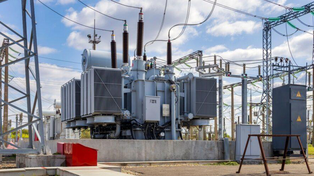
The transformer supplier normally provides equipment dimensions, support locations, masses and interface information within its contracted scope. The civil designer evaluates the foundation and anchorage using those inputs, the site investigation and the applicable project design criteria. The EPC team coordinates the boundaries and controls the drawing revisions. Identify these responsibilities explicitly; do not assume that a general arrangement includes a complete foundation design.
Start with a single interface register. Each item should carry a document reference, revision, responsible party, required date and approval status. Keep preliminary values visibly different from released-for-construction values. A comment such as “dimensions to be confirmed” cannot quietly become a construction instruction.
Our custom engineering solutions page describes the equipment-matching context. The practical next step is an agreed exchange of drawings and project inputs, with the civil design responsibility retained by the competent project designer.
Choose a defined reference point and orientation for the transformer, foundation and cable routes. Show the high-voltage and low-voltage sides, centre lines, support elevations and terminal reference points. Confirm whether a view is taken from the marshalling-box side or the opposite side.
Mirrored arrangements are easy to miss in separate drawing packages. They become obvious when the anchor pattern, cable trench and terminal positions are overlaid. The review must compare the same physical orientation, not just matching dimension strings.
A shipping document may describe a transformer without radiators, oil or other removable equipment. The foundation supports the installed assembly. Request clearly identified transport and operating masses, the component configuration used for each, and the centre of gravity where needed for the project design.
Total mass alone does not define support reactions. The arrangement of the tank, radiators, conservator, accessories and separate structures affects how loads reach the supports. Where the civil engineer needs support reactions or lateral-load information, agree the required format and design cases with the manufacturer before release.
For equipment such as a 31,500 kVA oil-immersed substation transformer, use the approved order-specific load data. A product-page rating identifies the equipment class; it is not a substitute for a certified foundation input sheet.
The temporary condition can differ from the final condition. Moving the transformer onto rails, positioning it with approved jacking arrangements or installing a separately supported cooler can introduce different reactions and access needs. These operations require the manufacturer’s handling instructions and a competent installation plan.
The foundation review should identify those cases without prescribing an improvised lifting method. It should also identify who checks temporary works and who releases the foundation for equipment placement. Operating weight divided by the floor area is not an adequate structural assessment.
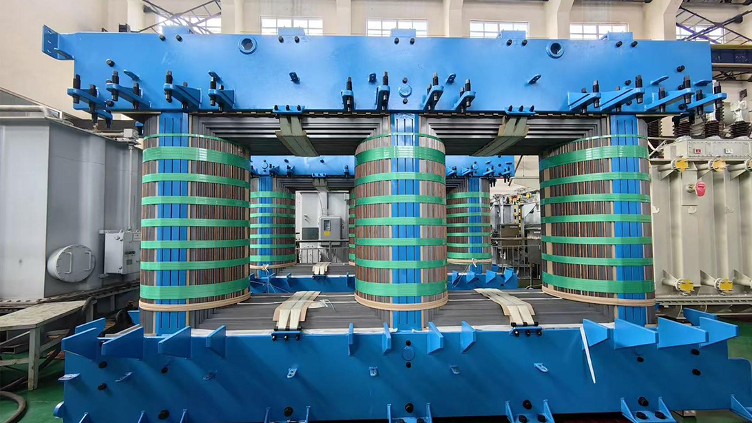
Ask for the base detail, not only the outline length and width. Confirm support-point spacing, bearing surfaces, wheel or skid arrangement, anchor-hole coordinates, hole sizes and any intended movement restrictions. Identify which parts are supplied with the transformer and which belong to the installation contractor.
The structural designer must determine the anchorage system from the project loads, concrete conditions and governing design criteria. An equipment drawing with holes does not establish anchor capacity. Conversely, a civil drawing with a standard bolt pattern does not prove that the transformer base can accept it.
Where wind or seismic requirements apply, define the design basis and required equipment data explicitly. Do not choose anchor diameter, embedment or restraint details from a generic transformer article. The load path through the equipment base, fixings and foundation must be reviewed together by the responsible engineers.
For a 35 kV or 46 kV power transformer, terminal and accessory arrangements can change between projects even when the voltage class is the same. Freeze the order-specific base and connection drawings before finalizing the civil interface.
| EPC interface | Common risk | What should be confirmed |
|---|---|---|
| Equipment mass and reactions | Shipping data used for permanent foundation design | Operating configuration, component masses, support reactions and required temporary load cases. |
| Coordinates and orientation | Anchor or trench arrangement mirrored on site | Common datum, viewing direction, terminal sides, elevations and drawing revisions. |
| Base and anchorage | Standard civil anchor pattern does not match the equipment | Base detail, bearing points, hole geometry, restraint concept and structural design responsibility. |
| Oil containment and drainage | Nominal pit volume overlooks other design inputs | Agreed containment basis, oil inventory, displacement, drainage treatment and local approval requirements. |
| Cable and busduct interfaces | Foundation position forces loads into bushings | Terminal coordinates, cable approach, independent supports and movement allowances. |
| Access and removal space | Equipment fits but cannot be maintained or replaced | Door travel, radiator removal, lifting access, escape routes and future removal envelope. |
| Construction release | Unresolved supplier revision reaches the construction team too late | Approved interface register, signed hold-point release and controlled distribution of revised drawings. |
For an oil-immersed unit, identify the oil inventory in the agreed operating configuration and the containment philosophy required by the owner and the applicable local rules. The civil designer may need to consider equipment displacement, rainfall, firewater or shared drainage arrangements, depending on the project. Do not reduce this to a universal percentage quoted without context.
Check how the containment area will be inspected and maintained. A drain shown on a drawing is not proof that contaminated liquid can be discharged safely. The operating procedure, isolation arrangement and treatment or disposal route must be defined by the responsible site team.
Coordinate cable penetrations with the containment design. A trench or duct can become an unintended path for liquid if its interface is not addressed. Confirm the required seals, fire barriers and drainage separation through the appropriate disciplines rather than assigning all of them to the transformer manufacturer.
Containment walls and floor-level changes can interfere with valve operation, sampling access, marshalling-box doors or equipment removal. Review these features in section as well as in plan. An arrangement that appears clear from above may put a valve behind a wall at working height.
The objective is not to eliminate every surrounding structure. It is to make the constraints visible early enough to choose a maintainable arrangement and document the accepted trade-offs.
The electrical contractor needs terminal coordinates, allowable connection arrangements and the manufacturer’s interface limits. The civil contractor needs trench and support locations. If these two packages develop independently, the final cable route may force a bend or offset that the termination was never designed to accommodate.
Check the terminal elevation against the finished support elevation and the cable entry point. Include the connection hardware and required working space. Confirm cable support responsibilities so that the cable system does not rely on the bushing as a structural support.
For a rigid busduct connection, review tolerances, installation sequence and any required allowance for relative movement. Do not assume that forcing two flanges into alignment is an acceptable way to absorb a civil dimensional error. The supplier and busduct designer should agree the permitted interface conditions.
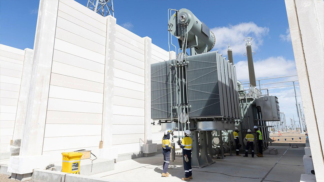
Draw the equipment as it will operate and as it will be serviced. Show open doors, removable radiators, access to cooling fans, marshalling cabinets and the route for routine inspection. Identify the handling space required for major removable components from the manufacturer’s documentation.
A transformer can pass through an unfinished building and become trapped after later walls, pipe racks or roof structures are installed. The EPC team should review the future removal route, not only the first delivery. If removal depends on a demountable wall or removable roof section, record that requirement in the final design and handover documents.
Keep permanent access distinct from temporary construction access. A crane position used during initial erection may be occupied by operating plant later. This matters to future outage duration and should be an owner-visible decision before the layout is frozen.
A hold point is useful only if it has a defined release condition. “Civil drawing submitted” is not the same as “civil interface approved.” Tie the release to the specific equipment data required for that stage, and record any limitations on the approval.
Procurement should require delivery dates for the foundation input sheet and revised general arrangement, not just a final equipment delivery date. Late interface information can put the construction sequence at risk even when manufacturing remains on schedule.
| Hold point | Required evidence | Release owner |
|---|---|---|
| Before foundation design freeze | Agreed equipment configuration, masses, support geometry, site criteria and interface register | EPC discipline leads with supplier input and responsible civil designer. |
| Before concrete placement | Approved construction drawing, surveyed coordinates, anchor template and closed critical comments | Civil quality team and designated project approver. |
| Before shipment release | Final equipment configuration, dimensional inspection records and disposition of interface deviations | EPC package engineer and supplier quality representative. |
| Before transformer placement | Foundation acceptance record, surveyed levels, access readiness and approved installation plan | Site installation lead with civil and safety approvals. |
| Before energization handover | Completed installation records, accepted deviations and coordinated electrical site-test evidence | Authorized commissioning team and owner representative. |
Agree the dimensional inspection scope while the equipment is still accessible at the factory. Relevant checks can include support centres, anchor-hole positions, terminal orientation and the location of major accessories. The contract should identify what will be recorded, who witnesses it and how a deviation is resolved.
Do not confuse this mechanical interface check with electrical factory testing. A transformer may meet its electrical test requirements while its base arrangement still conflicts with an outdated foundation drawing. Both evidence sets must refer to the same final configuration.
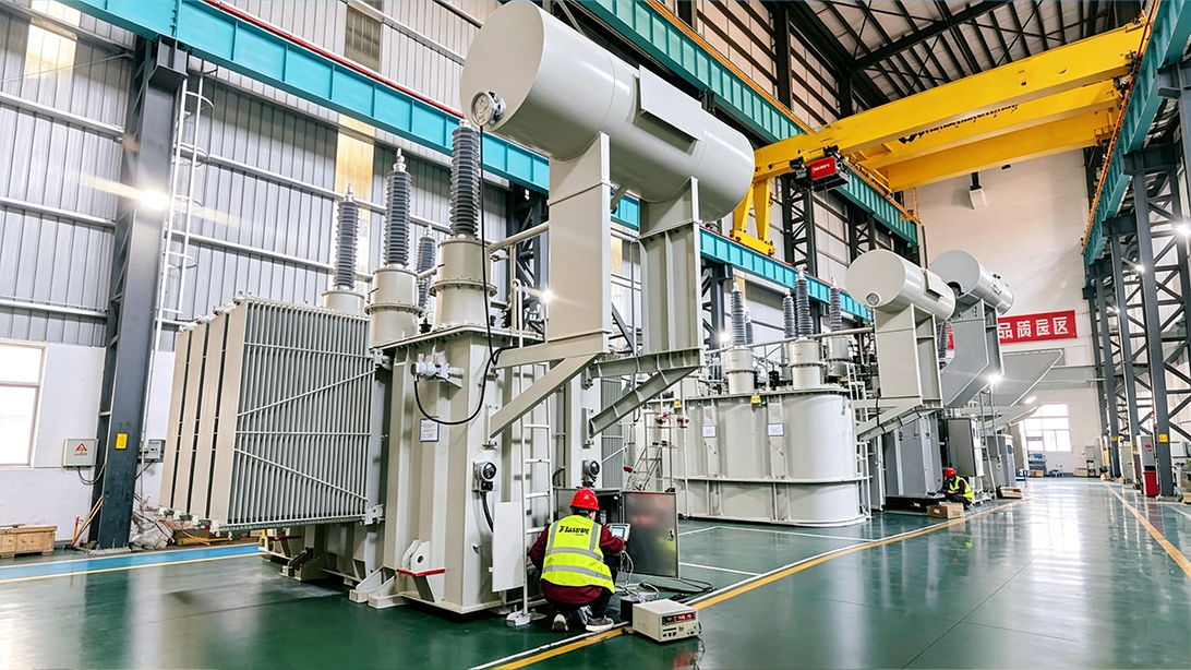
After construction, compare the surveyed foundation with the released equipment drawings before delivery equipment is positioned. Record actual levels and coordinates, and resolve discrepancies through engineering review. Site personnel should not alter the transformer base or anchorage arrangement simply to make a mismatch disappear.
At commissioning, carry unresolved interface items into the controlled punch list. Our transformer site acceptance and handover guide addresses the later commissioning stage; foundation release is an earlier gate that should already be closed.
The owner needs a traceable record of the installed arrangement. Include the accepted general arrangement, foundation and anchor drawings, survey results, equipment configuration, approved deviations and relevant installation records. Identify assumptions that future replacement or modification work must not overlook.
Keep document revisions linked to the transformer serial number and project equipment tag. If a radiator arrangement or base detail changed during execution, the final package must show that change. A technically correct superseded drawing can be more misleading than a clearly marked preliminary one.
Questions arising after handover can be routed through Zisheng Electric’s technical support and after-sales service, with the equipment identification and relevant drawings attached. An initial engineering response should not be confused with a guaranteed site attendance or repair completion time.
For a transformer foundation interface review, send the single-line diagram, transformer datasheet, preliminary layout, foundation concept, site conditions, structural design criteria and installation constraints. Include the project’s drawing schedule and the dates when civil construction decisions must be frozen.
Zisheng Electric can support technical matching for oil-immersed power transformers and related substation equipment against the project capacity, voltage level, environment and specification. The equipment package and civil design should be coordinated through the named EPC discipline leads. Our engineering team will review the requirements and respond to project inquiries within 24 hours.
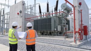
Coordinate transformer fire protection interfaces for EPC substations, including fire walls, oil containment, detection, suppression, breaker trips, SCADA, integrated testing and handover evidence.
View details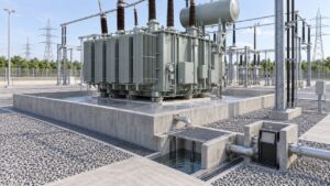
Plan transformer oil containment design for EPC substations by coordinating oil inventory, bund capacity, drainage, fire strategy, civil interfaces, construction inspection and pre-energization acceptance.
View details
Coordinate transformer fire protection for EPC projects: separation, oil containment, drainage, detection, suppression, control logic, FAT and site testing.
View details
In EPC projects, a transformer room must be designed as an operating space, not just a rectangle around the tank. Zisheng Electric engineers explain essential layout considerations including safety clearances, ventilation, lifting routes, and main...
View details