zishengelectric



news
News Center
Providing high-quality power to the world
Search productSearch post
news
Providing high-quality power to the world
Zisheng Electric treats transformer cooling stage acceptance as a check of the complete operating chain: a valid cooling demand, the intended fan group, actual equipment response, useful feedback and an understood consequence if that response is lost. A contactor closing is one observation. It is not, by itself, proof that the transformer has the cooling capability assumed in its operating schedule.
This distinction matters at EPC handover. A transformer can arrive with correct radiators and fans, yet the site wiring, control mode or alarm mapping may leave the operator with an incomplete picture. The acceptance plan should establish what each stage does, how its availability is reported and which approved loading basis applies when equipment is unavailable.
The workflow below is intended for projects with staged forced-air cooling. It must be adapted to the purchased transformer and controller. It does not prescribe universal temperature settings, delays, fan quantities or reduced-cooling ratings.
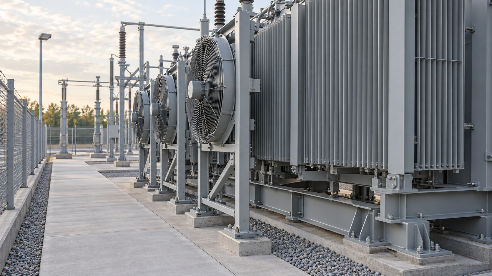
Start with the approved cooling schematic and transformer rating schedule. Identify each radiator bank, fan group, motor circuit, local isolator, control supply and temperature input. Then mark the boundary between the transformer package, the auxiliary distribution board, the station control system and the operator interface.
A clear boundary prevents two common gaps. The transformer supplier may assume that the EPC contractor proves the incoming supply and remote indications. The EPC contractor may assume that factory testing already proved every installed connection. List those responsibilities explicitly, including who signs off changes made during site assembly.
Mechanical completion establishes that the supplied assembly is installed according to its approved requirements. Check guards, mounting, clearances, accessible isolators and the relevant inspection records. The separate radiator assembly verification guidance addresses the cooling assembly and its installation evidence.
Functional acceptance follows that release. It checks whether the system behaves correctly when the agreed control conditions are presented. Do not use a successful control simulation to close an outstanding physical obstruction, incomplete fan installation or unresolved mechanical defect.
Write the state table before the test sequence. Each row should describe the initial condition, the approved stimulus, the expected response and the evidence required. The table below is a planning model. The project’s approved drawings and manufacturer instructions determine the actual behaviour.
| State or condition | Expected result to define | Evidence to collect | Release question |
|---|---|---|---|
| No cooling demand | Standby behaviour, any periodic exercise and indication state | Mode selection, input values and observed group status | Is the controller following the approved standby philosophy? |
| First stage demanded | Correct first group starts after its configured logic conditions | Command, fan identity, physical response and available feedback | Does the actual group match the drawing and rating basis? |
| Additional stage demanded | Required additional group operates without unintended loss of the first | Both group responses and event sequence | Is the full commanded arrangement available? |
| One fan circuit unavailable | Specified fault indication and any approved substitute action | Safely simulated failure, alarm identity and restoration record | Can the operator identify the affected equipment? |
| Control input invalid | Defined sensor-failure behaviour and alarm | Approved simulation method, resulting state and controller indication | Is the fallback behaviour deliberate and documented? |
| Supply interrupted and restored | Agreed restart sequence, retained settings and correct alarms | Initial state, restart observations and cleared or retained alarms | Does recovery avoid an undocumented operating mode? |
| Local/manual mode selected | Clearly defined authority and availability indication | Local response, remote display and mode-restoration check | Will the next operator know that automatic control is unavailable? |
Do not fill this table with generic “pass” statements before testing. If the required behaviour is unclear, resolve it with the designer and supplier first. A test technician should verify an approved requirement, not become the person who decides the plant’s cooling philosophy on site.
Define the meaning of every signal. “Fan start command,” “contactor energized,” “motor circuit healthy” and “airflow established” are different observations. A controller may only receive some of them. Label the operator display according to what is actually measured, rather than presenting a command as confirmed running feedback.
Reinhausen’s automation overview describes cooling control that uses load and thermal conditions. Its ETOS operating instructions also describe optional cooling monitoring functions. These are examples of available functionality, not proof that the same monitoring is included in every transformer package. Confirm the purchased configuration in the approved documents. See the manufacturer’s automation overview.
Before site testing, record the controller identity, applicable software revision where relevant, approved settings and drawing revision. Include the source of the cooling demand, any start and stop differentials, time delays, group alternation, exercise routines and manual overrides. A marked-up schematic alone may not capture settings held inside a programmable device.
Use a controlled list of inputs and outputs. Give each point its terminal reference, source, destination and meaning. This is especially useful when a supplier uses a general alarm contact while the station system expects individual motor-circuit alarms. The mismatch should be resolved before the commissioning team starts proving remote displays.
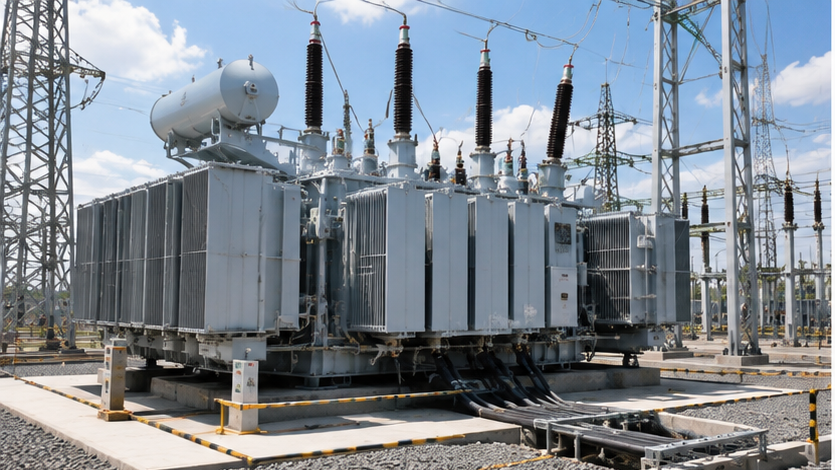
The fan motor supply and the control or alarm supply may have different origins. Show their actual relationship on the test boundary. A loss of fan power should not be assumed to remove, or preserve, alarm visibility without checking the circuit.
The transformer auxiliary power specification guide can support that interface review. For cooling acceptance, extract the particular supply paths, protective devices and terminal references that the test team must verify. Keep unrelated auxiliary loads outside the scope unless they affect the proposed test.
Begin with an equipment walkdown against the approved fan-group schedule. Confirm that labels in the cabinet correspond to the physical fans and radiator banks. Where equipment was disconnected for transport, include the reconnected circuits in the site verification scope rather than assuming that the factory group allocation has been preserved.
Under the authorized commissioning procedure, verify physical operation from the permitted observation position. Check rotation or airflow direction against the manufacturer’s marked direction and instructions. A running motor can still be associated with the wrong group or an incorrect installation; record the equipment identity along with the observation.
For each commanded stage, document the starting mode and the actual sequence. Record which group operated, what the control cabinet indicated and what reached the station interface. Where timing is an acceptance requirement, use a suitable time record and the approved tolerance. Do not substitute a casually timed observation for a specified measurement.
Then verify the return path: removal of demand, the specified stop behaviour and any retained status. Repeated starts, alternation or exercise routines should be included only where they form part of the supplied design. The test record should make omitted optional functions explicit so that absence is not later mistaken for a defect.
Agree the simulation method and authorization before testing. Use the manufacturer’s and project’s approved test facilities or controlled simulation procedures. Do not stall a fan, defeat a protective device or intentionally overheat the transformer merely to create an alarm. Actual switching and electrical testing belong to the authorized commissioning team.
A useful failure-state record identifies what was simulated, which protection or monitoring path was exercised, and which parts of the physical chain were not tested by that method. For example, simulating an alarm input verifies the downstream indication path; it does not prove that the physical sensor detects its intended condition.
Check the actual allocation. One stage may contain several separately protected motors; alternatively, a shared supply or control element may affect multiple groups. An individual fan fault and a common supply failure therefore need different test cases and different operator descriptions.
If the design provides standby groups or automatic substitution, verify the trigger, substituted group and resulting status. If it does not, record the required operating response from the approved instructions. The word “redundant” should be supported by an identifiable arrangement and its tested behaviour.
Agree how an invalid temperature input is recognized and what the controller should do. Depending on the supplied system, the response may involve a specific fallback and an alarm. The commissioning team should not choose that response by preference; it must match the approved design.
Likewise, verify restart behaviour after the defined supply interruption. Confirm whether settings, mode selections and latched indications are retained as intended. Reinhausen’s ETOS operating instructions provide an example of manufacturer-specific monitoring parameters. Use the manual for the installed controller when preparing the actual procedure.
The handover package should tell the owner what to do with an unavailable cooling group. Do not derive an allowable transformer load by dividing the rating by the number of fans. Cooling contribution is not established by simple fan counting, and a nameplate with several ratings does not describe every possible partial-failure arrangement.
Request the manufacturer’s declared operating basis for the relevant cooling configurations and the owner’s approved response instructions. Make any unresolved limitation visible in the commissioning release. A functioning alarm is valuable only when the person receiving it can identify the affected equipment and locate the required action.
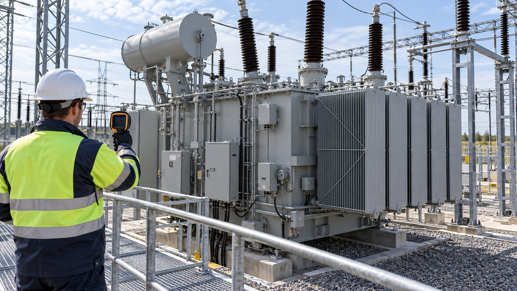
A brief functional run proves the tested controls and observations under those conditions. It does not establish full thermal performance at every load and ambient condition. Identify the design or test evidence supporting the declared rating separately, and record any first-service observations required by the contract.
This distinction also improves defect handling. A missing feedback signal, a failed motor circuit and a concern about thermal performance belong to different investigations. Preserve the relevant settings, load information, ambient observations and event history so the supplier receives a useful technical enquiry.
Organize the final package by equipment identity and operating state. Include the approved schematic, fan-group schedule, controller configuration record, supply interfaces, completed test sheets, resolved discrepancies and outstanding restrictions. Attach photographs where they clarify fan identity or installed labels, with dates and references.
Record restoration after every simulation. The final review should reconcile temporary test conditions, mode selections, protective-device state and approved settings. Assign the release to named project roles rather than relying on the last technician’s informal assurance that the system is back to normal.
Keep the operator explanation short enough to use during an alarm: what the indication means, which cooling group is affected, where the approved response is recorded and who to contact for technical support. That makes the detailed evidence behind the test sheets accessible during actual operation.
For transformer cooling stage acceptance, provide Zisheng Electric with the drawings, data sheets, load list, technical specifications, single-line diagram, grid parameters and environmental conditions. Include the cooling schematic, fan-group allocation, auxiliary supply details, signal list and proposed commissioning scope so that the equipment and site interfaces can be reviewed together.
Zisheng Electric’s 31.5 MVA, 35 kV oil-immersed transformer and 25 MVA substation transformer provide starting points for project enquiries. Confirm the required cooling configuration in the equipment data sheet, then build acceptance around that configuration. The handover should show what was installed, what was tested and what the owner may rely on in each approved operating state.

Define a transformer SCADA point-to-point test with clear boundaries, signal evidence, data-quality checks, event records and controlled retesting.
View details
Real case from an Indonesian industrial park. Checklist for evaluating transformer suppliers on technical capability, performance guarantee & on-site service, compliant with IEC 60076, PLN, SEC and more grid certifications.
View details
Build an EPC transformer document register that controls submittals, revisions, approval codes, manufacturing release, FAT records, logistics files and final handover evidence.
View details
Build a transformer inspection and test plan that links hold points, witness notices, test records and release authority to an EPC project's delivery schedule.
View details