zishengelectric





news
News Center
Providing high-quality power to the world
Search productSearch post
news
Providing high-quality power to the world
Zisheng Electric recommends preparing a transformer site assembly supervision plan before the transformer reaches site. Large transformers are often shipped with bushings, radiators, conservators, coolers, pipework and accessories removed. Reassembly is therefore not a simple mechanical task. It is the controlled restoration of the configuration that was inspected and tested at the factory.
For an EPC contractor, the plan must align the transformer manufacturer, erection subcontractor, logistics team, oil-treatment team, civil contractor, electrical contractor, consultant and owner. This guide explains the technical interfaces, evidence and release points that should be defined. It is not a project record; any example is hypothetical and must be replaced by the approved manual, method statement and project requirements.
The first page should identify the transformer, purchase order, site, approved drawings, shipping condition and planned assembly dates. It should list which components arrive fitted, which are removed for transport and which are supplied as loose accessories. The plan must also state who performs the work and who provides supervision, tools, lifting equipment, consumables, dry air or nitrogen, vacuum equipment and oil-processing equipment.
Supervision does not transfer the contractor’s safety or execution responsibility unless the contract explicitly says so. The responsibility matrix should distinguish instruction, execution, inspection, witness and approval. Ambiguous wording such as “vendor to assist installation” often causes disputes over cranes, technicians, oil, filters, gaskets, test equipment and working hours.
Assembly should not start only because the transport vehicle has arrived. Verify the foundation, access, fire containment, earthing grid, working platform, lighting, weather protection and housekeeping. If the active part or tank interior may be exposed, the environmental controls in the manufacturer’s instructions must be available before opening any blanking plate.
| Pre-assembly interface | Acceptance question | Risk if unresolved | Release evidence |
|---|---|---|---|
| Foundation and rails | Are level, elevation, anchors and wheel stops within approved tolerances? | Tank distortion, misalignment or unsafe jacking | Civil survey and signed release |
| Access and lifting | Can the crane reach each lift with verified capacity and radius? | Dropped load or damaged accessory | Lift plan, crane certificates and exclusion zone |
| Weather protection | Can internal exposure limits be maintained? | Moisture or contamination enters insulation | Enclosure, forecast review and environmental log |
| Oil equipment | Are hoses, tanks, filters and vacuum equipment clean and suitable? | Oil contamination or incomplete vacuum | Equipment inspection and cleanliness record |
| Earthing | Is the permanent or temporary earthing arrangement ready? | Unsafe work and later interface conflict | Earthing continuity and connection check |
| Documentation | Are latest drawings, manuals and packing lists available? | Incorrect assembly or missing parts | Controlled document register |
Record the transformer and crates before disturbing evidence. Check impact indicators where specified, seals, pressure or oil level, tie-down marks, damaged paint, shifted covers, broken gauges and wet packaging. Compare crate numbers with the packing list. Any abnormality should be photographed, quarantined where necessary and reported through the project’s damage or nonconformance process.
Do not assume that a normal external appearance proves internal condition. Conversely, a triggered indicator is not by itself proof of damage. It is a reason to follow the approved inspection and escalation procedure, review transport data and agree any additional checks before assembly.
Every loose component should be matched to the transformer tag, packing list, drawing and installation position. Bushings and current transformers may have phase-specific or serial-number-specific documentation. Pipework, valves and radiators may be marked for location and flow direction. Mixing components between similar units can invalidate records or cause dimensional problems.
Create an unpacking register showing crate number, item description, quantity, condition, identification, storage location and action for damage or shortage. Keep protective covers in place until immediately before installation. Store moisture-sensitive components according to the manufacturer’s instructions.
If the transformer is opened to atmosphere, the transformer site assembly supervision plan should define acceptable environmental conditions, exposure time, air quality, dew-point or relative-humidity controls as required, foreign-material exclusion and resealing rules. The exact limits must come from the approved manufacturer instructions; do not invent universal values.
Use a tool and material accountability log. Prevent loose washers, wire, packaging, dust and moisture from entering the tank. If conditions move outside the approved range, stop the work, protect the opening and obtain engineering direction. A schedule delay is preferable to hidden contamination.
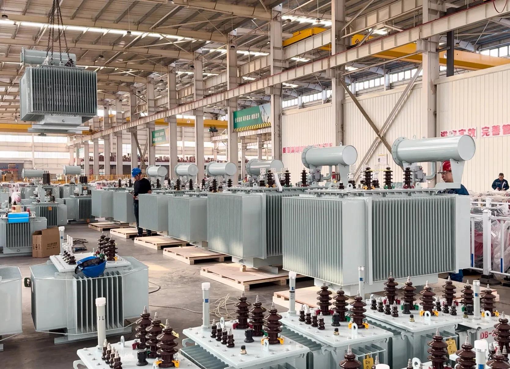
Bushing installation combines lifting, sealing, conductor connection and insulation coordination. Verify bushing type, voltage class, current rating, serial number, phase, test tap condition and drawing position. Inspect porcelain or composite sheds, flange, gasket surfaces and terminals before lifting.
Use the approved lifting device and orientation. Protect the lower end from impact and contamination. Tightening values and sequence must follow the manufacturer’s instructions. Internal lead connections require correct contact surfaces, hardware, torque and clearance. After installation, verify oil level where applicable, test-tap earthing or connection, terminal orientation and phase marking.
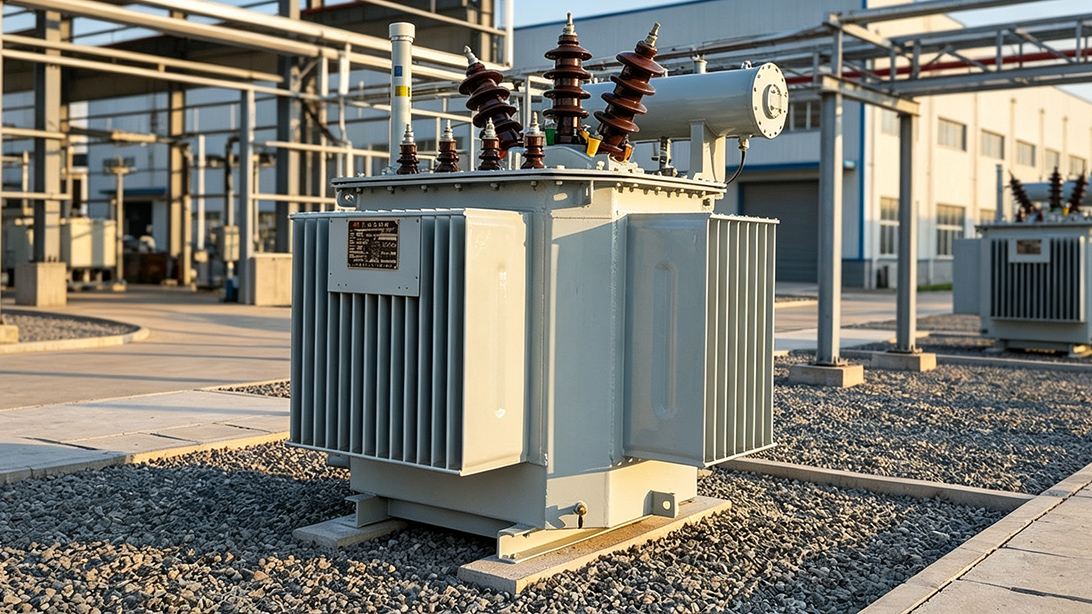
Confirm each radiator or cooler is clean, undamaged and assigned to the correct location. Check blanking plates, valve positions, gasket type and flange faces. Remove transport covers only when ready to connect. Do not reuse a compressed gasket unless the approved instruction permits it.
Pipework must be supported without forcing alignment through bolt tightening. Fans, pumps and flow indicators need correct orientation, cable routing and identification. After assembly, perform the specified leakage and functional checks. The control system must demonstrate each cooling stage, alarm and trip interface under the approved cause-and-effect logic.
The conservator arrangement may include an oil-level indicator, bladder or diaphragm, breather, pipework and isolation valves. Confirm shipping locks and temporary blanks are removed only at the correct stage. Buchholz relays or other gas-actuated devices must be installed in the approved orientation and pipe slope, with accessible sampling and test points.
Protective-device contacts should be traced to the marshalling box and then to the plant control system. Mechanical installation and electrical loop checking must use the same tag numbers. An accessory that looks correctly fitted can still be ineffective if a valve remains closed, a transport lock remains engaged or a contact is wired to the wrong alarm.
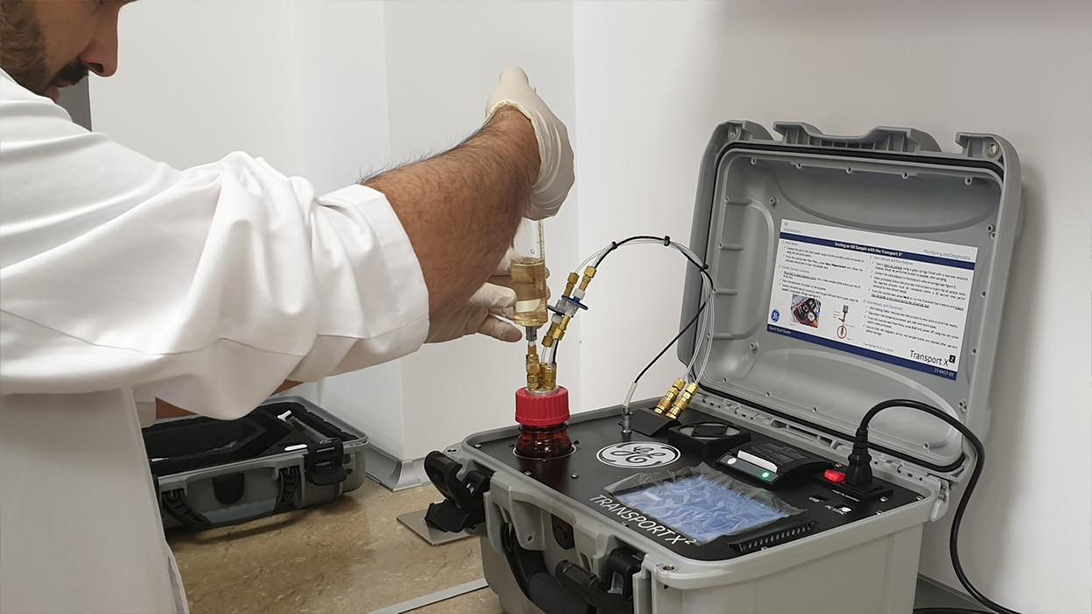
Oil filling is a separate controlled process linked to assembly. Define oil ownership, batch traceability, storage, sampling, treatment, vacuum application, filling sequence and acceptance testing. IEC 60076-1 includes general provisions relevant to liquid preservation and tank tests, while the transformer manual and project specification provide the unit-specific method.
Hoses, temporary tanks and processing equipment can introduce moisture or particles. Inspect and clean them before connection. Record vacuum and filling parameters continuously where required. After filling, allow the specified settling time, vent trapped air at designated points, inspect leaks and confirm final oil levels under the applicable temperature condition.
The matrix should be agreed before mobilization. “Witness” means the activity may proceed after the contractual notice if the witness is waived; “hold” means work cannot proceed without release. Apply the project definitions, because terminology varies.
| Activity | Installer | Manufacturer supervisor | EPC/owner | Suggested control |
|---|---|---|---|---|
| Site readiness survey | Provide access and evidence | Review equipment needs | Approve release | Hold |
| Transport inspection | Unpack under control | Assess equipment condition | Witness and record | Witness |
| Internal exposure | Execute method | Direct equipment-specific steps | Verify conditions | Hold |
| Bushing and accessory assembly | Lift and install | Check sequence and connections | Review records | Witness |
| Final internal inspection | Present clean work area | Inspect and sign | Release closure | Hold |
| Oil filling and leak check | Operate equipment | Verify method | Witness results | Witness/Hold per contract |
| Assembly completion | Close punch items | Issue supervision report | Accept handover to testing | Hold |
Torque records should identify the connection, specified value, tool identification, date and technician. Not every bolt needs an individual record, but critical electrical connections, bushing terminals, internal leads and specified flange groups should be controlled according to the approved method. Marking paint may show movement after tightening but does not replace the torque record.
Capture any approved change to cable-box orientation, bracket position, conduit route or accessory location. Redline drawings while the work is visible. Waiting until handover to reconstruct changes from photographs creates errors in as-built documents and spare-parts data.
Assembly completion is not energization approval. The release should confirm that the configuration matches approved drawings, internal exposure is closed, valves are in the correct state, oil work is accepted, leaks are cleared, transport locks are removed, accessories are functional, earthing is connected and temporary covers or jumpers are controlled.
The handover package should include the site-readiness release, transport inspection, unpacking register, environmental log, component records, torque sheets, oil-processing records, leakage checks, functional checks, photographs, nonconformance closures and updated drawings. Remaining punch items must be classified by risk and assigned before site acceptance tests begin.
Example only; the manufacturer’s approved manual governs the actual unit.
Send the approved transformer drawings, packing list, shipping condition, site layout, foundation release, lifting study, assembly schedule, oil specification, environmental data, contractor responsibility matrix, method statement, inspection plan and required handover format. Related EPC resources include the transport damage inspection guide, transformer oil filling procedure, site acceptance test checklist and foundation interface review. Product references include our oil-immersed transformer range, 20 kV-class distribution transformer and power-distribution transformer solutions.
A practical transformer site assembly supervision plan protects the factory-tested configuration while responsibilities pass between logistics, civil, mechanical, electrical and commissioning teams. It also creates the evidence needed to release the equipment to testing without relying on memory or unverified photographs. Our engineering team will review the requirements and respond to project inquiries within 24 hours.
Why Tropical-Ready Design Determines Project Reliability A transformer failure in a Vietnamese coastal industrial park or a Thai solar farm is never just a component issue. Production halts. Revenue slides. The unplanned maintenance costs no proje...
View details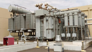
Build an EPC transformer document register that controls submittals, revisions, approval codes, manufacturing release, FAT records, logistics files and final handover evidence.
View details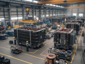
In EPC projects, transformer issues rarely appear during the quotation stage. They usually become visible later — during installation, inspection, or commissioning, when changes are costly and project schedules are already under pressure. A transf...
View details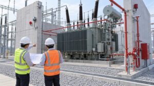
Coordinate transformer fire protection interfaces for EPC substations, including fire walls, oil containment, detection, suppression, breaker trips, SCADA, integrated testing and handover evidence.
View details