 zishengelectric





news
News Center
Providing high-quality power to the world
Search productSearch post
news
Providing high-quality power to the world
An EPC transformer cable schedule should be reconciled before equipment manufacture. In an EPC substation, transformer delivery can be on time and still fail at installation because the cable schedule was never reconciled with the final tank and switchgear interfaces. At Zisheng Electric, we normally review the single-line diagram, GA drawing, cable schedule and termination details as one package. This article explains the checks that prevent late gland-plate changes and energization delays.
The cable schedule connects the transformer, MV switchgear, LV board, protection panel, marshalling box and site control system. It defines where every power, alarm, trip, indication and communication cable starts and ends. A transformer datasheet may be technically correct while the project still has the wrong gland position, cable bending radius or terminal numbering.
Before steelwork is released, confirm the cable entry direction, gland-plate size, number of spare holes, terminal orientation, control-voltage level and segregation between power and control wiring. If the EPC contractor changes from bottom entry to side entry after tank fabrication, the repair is slow and can compromise coating or sealing.
| EPC interface | Common risk | What should be confirmed |
|---|---|---|
| MV cable box | Termination kit does not fit or phase spacing is wrong | Cable size, screen earth, stress cone, phase order and access clearance |
| LV busduct or cable | Flange and neutral connection are misaligned | Reference dimensions, thermal rating, flexible link and earth bonding |
| Protection and control | Alarm or trip arrives at the wrong terminal | Terminal schedule, contact voltage, ferrule numbering and cause-and-effect matrix |
| Communications | SCADA point list is incomplete | Protocol, gateway, cable type, shielding and FAT simulation scope |
The transformer drawing should show the cable box orientation, phase spacing, cable support and minimum bending radius. Do not leave the contractor to interpret a generic box outline. Confirm whether the cable screen is bonded at one end or both ends, how the neutral is brought out, and where the earth bar is located. For parallel cables, show the number of runs and lug arrangement so heating and access can be checked.
Oil temperature, winding temperature, pressure relief, Buchholz relay, oil level and fan controls often use different contact arrangements. The project cause-and-effect matrix should state which alarm is annunciated, which trip is hardwired and which signal is monitored by SCADA. At FAT, simulate each contact and record the terminal number, relay response and reset behavior. A generic “alarm tested” statement is weak evidence for handover.
Confirm whether the transformer accessories use AC or DC control power, the permitted voltage tolerance and the required miniature circuit breakers. Check the earthing bar location, tank bonding straps, cable screen connections and the approved shielding and protective-bonding arrangement; do not create an isolated protective-earth system.
Use a controlled revision for the GA drawing, cable schedule, terminal plan, wiring diagram, protection list and packing list. During design review, record open points with an owner and due date. FAT should include point-to-point checks, alarm and trip simulation, ratio and routine electrical tests, nameplate verification and a review of outstanding comments. Release for shipment only when the approved drawing revision is reflected in the equipment and documentation package.
At site, inspect cable entries before termination, photograph the gland plates, verify phase identification and check that temporary shipping protection has been removed. Perform the approved cable and equipment tests with sensitive devices isolated as required, prove continuity and protective bonding, and compare the as-built terminal numbers with the approved schedule. The commissioning dossier should contain red-line drawings, test records, spare lists, manuals and training notes.

Start with a unique cable identifier and preserve it through design, procurement, installation and testing. Each row should identify the source equipment, destination equipment, circuit function, voltage class, cable construction, conductor material, core count, cross-section, estimated length, route and termination drawing. A description such as “transformer alarm cable” is not enough when several devices share a marshalling cabinet and different contacts have different operating duties.
Separate confirmed data from provisional values. Early route lengths may be estimates; cable diameters may await supplier selection; terminal references may depend on the final protection scheme. Mark these items with an owner and closure date. A blank cell can be mistaken for “not applicable,” whereas a clearly controlled open item prevents fabrication or procurement from proceeding on an unapproved assumption.
The transformer supplier usually defines equipment terminals and available entry space. The EPC designer coordinates the complete circuit and the cable contractor installs it. The switchgear or control-system supplier owns the destination terminal interface. Nominate one party to reconcile the end-to-end schedule. Otherwise, each supplier may approve its own drawing while the cable still has incompatible gland sizes, missing cores or inconsistent ferrule numbers.
For spare cores, state the identification, insulation, termination and storage arrangement. Do not assume a spare core is available for any future signal: voltage rating, segregation, screening and circuit safety must still be suitable. Record spare terminals separately from spare cable cores because one can exist without the other.
Check the selected cable’s actual outside diameter against the gland’s certified clamping range. Conductor cross-section alone does not determine outside diameter; insulation, screen, armour and sheath construction also matter. Confirm gland thread, hole size, sealing washer, locknut access, armour termination and available wrench space. Leave sufficient edge distance and spacing to install and tighten adjacent glands without damaging the enclosure or cable sheath.
For single-core AC power cables, the arrangement of phases and the magnetic properties of the entry plate require specific review. A ferromagnetic plate surrounding individual conductors can introduce unwanted heating. Obtain an approved plate material and phase-entry arrangement from the equipment designer; do not infer acceptability from a photograph or a standard multicore control-cable detail.
The cable box should not carry loads that belong on external supports. Verify cable weight, pulling tension, support spacing and fault-force restraint against the cable and equipment designs. Show the first support position and the three-dimensional approach to each termination. A cable may satisfy the bend radius on a plan drawing but fail it where the route changes elevation immediately below the box.
Allow room for termination kits, tools, phase identification and future inspection. Check both installation bend radius and final installed bend radius where the cable manufacturer distinguishes them. For parallel runs, review phase grouping, equalized impedance and connection geometry as part of the system design. A mechanically convenient arrangement is not automatically an electrically balanced one.
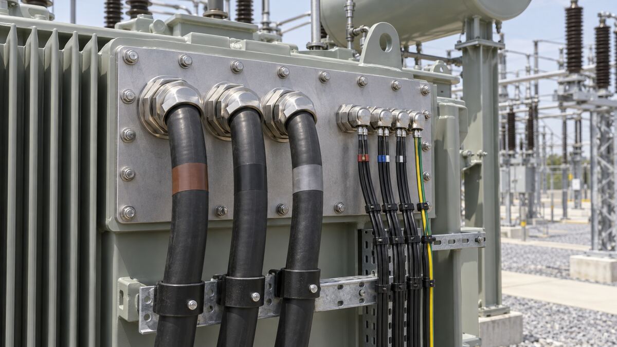
The termination drawing should state lug material, palm dimensions, bolt pattern, conductor preparation and the approved connection hardware. Aluminium and copper interfaces require the specified compatible connection system. Do not substitute a generic tightening torque: use the equipment and connector manufacturers’ approved values, including their instructions on washers, lubrication and inspection.
Control circuits should distinguish trip, alarm, auxiliary power, analogue measurement and communications. Review insulation ratings and segregation where circuits with different voltages share a cabinet. Shield termination depends on the signal system and EMC design; it should not be reduced to a universal rule to earth every shield at one end or at both ends. Identify the intended termination at each end and carry that requirement into installation inspection.
A device contact that operates a local indication circuit may not be suitable for directly interrupting a trip-coil load. Confirm contact rating against actual AC or DC duty, current and circuit characteristics. Where an interposing relay is needed, assign its supply, fusing, test access and failure indication. Identify which functions remain available after loss of the normal AC auxiliary supply.
The cable schedule should match these decisions. A late change from an alarm-only signal to a hardwired trip may require different segregation, additional cores or another terminal group. Review it through controlled change management rather than editing a single spreadsheet cell and assuming the connected drawings remain valid.
Use a limited number of explicit release gates. Before enclosure fabrication, approve entry direction, gland-plate outline and interface dimensions. Before cable procurement, approve construction, sizing assumptions and route allowances. Before termination, confirm the released terminal plans and selected termination kits. Before energization, close test records, drawing changes and safety-critical outstanding work.
For a practical example, an EPC team may change a cable route to avoid a drainage channel after equipment drawings have been approved. The review should check the new bend geometry, added cable length, voltage drop, protection implications, gland orientation and installation sequence. The impact is wider than the civil drawing. Use the same discipline described in transformer design change control for EPC projects.
Factory testing can prove internal wiring, accessory operation, terminal labels and the simulated response of supplied control equipment. It cannot prove a cable that has not yet been installed at site or a remote relay outside the factory scope. Define the simulated boundaries in the FAT procedure and reserve the complete trip path, remote indication and communications tests for the agreed integrated site procedure.
Record the stimulus, expected response, actual response and tested terminal numbers. For a temperature alarm simulation, distinguish testing a relay contact from verifying the complete sensing chain. For a trip test, define breaker isolation, interlocks and restoration controls before starting. Qualified personnel should execute the approved procedures; this article is a procurement and coordination guide, not a live-work instruction.
If a destination panel is unavailable at FAT, record the untested boundary and the later test owner. A signed factory checklist should not silently convert “not tested” into “passed.” At site, link the completion record to the same cable and terminal identifiers. Attach the relevant drawing revision so the evidence remains understandable after equipment replacements or future modifications.
Transformer accessory signals also depend on the supplied mechanical systems. Review the alarm and inspection interfaces alongside the transformer oil preservation system. Cable supports and clearances should also be coordinated with the project’s approved seismic qualification and anchorage requirements where applicable.

Deliver the final cable schedule in an editable format as well as the approved record copy. Include as-built routes, terminal plans, cable and gland specifications, termination-kit details, installation inspection records, approved test results and unresolved non-safety-critical items accepted by the owner. Preserve photographs of completed entries and labels before covers or permanent barriers hide them.
The operating team should be able to trace an alarm from the field device through the cable, terminal strip and relay to the control-system point. Demonstrate that traceability during handover using a sample of actual circuits. Explain isolation points, cabinet access and spare-core records without asking maintenance personnel to reconstruct the project from disconnected supplier manuals.
An EPC transformer cable schedule must reflect the equipment actually purchased. An oil-immersed transformer may include several oil-system and cooling signals, while a substation transformer arrangement introduces switchgear and station-control boundaries. A prefabricated substation can consolidate equipment, but its external cable interfaces still need clear ownership and dimensional approval.
Zisheng Electric can review the EPC transformer cable schedule together with related equipment interfaces. Provide drawings, data sheets, load lists, technical specifications, single-line diagrams, grid parameters, environmental conditions and installation-site conditions. Include cable construction, entry direction, control voltages, protection logic, SCADA points and the installation programme so the review can identify missing inputs before manufacture.
Our engineering team will review the requirements and respond to project inquiries within 24 hours.
Engineered Transformer Systems That Match Your Project Specifications A power system is only as strong as its weakest link. With over 15 years of manufacturing experience and transformers operating in more than 40 countries, we've seen how the rig...
View details
Coordinate transformer earthing interfaces for EPC projects: tank bonds, neutral grounding, core links, cable screens, surge arresters, FAT and handover.
View details
Coordinate transformer protection interfaces for EPC projects, including CT inputs, mechanical trips, alarms, relay logic, SCADA, FAT and handover.
View details
Control transformer design changes across EPC drawings, electrical studies, physical interfaces, manufacturing and acceptance. Define owners, evidence and release gates.
View details