 zishengelectric



news
News Center
Providing high-quality power to the world
Search productSearch post
news
Providing high-quality power to the world
Substation cable gland acceptance should establish that each installed cable entry matches the approved cable, enclosure and bonding design. A tidy row of glands is useful visual evidence, but appearance alone cannot confirm the sealing range, accessory combination or electrical continuity of the completed assembly.
For EPC teams, the most useful handover record connects a physical entry to its cable reference, gland designation, installation instruction and inspection result. This article describes that evidence workflow. Installation and testing must follow the approved project design and manufacturer instructions, with work performed under the site’s authorized isolation arrangements.
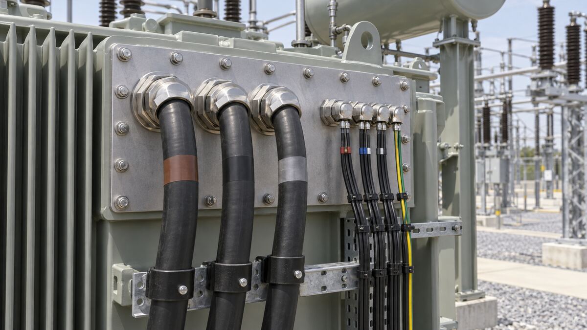
Identify the enclosure, panel or kiosk, its entry-plate reference and the cable entries covered by the inspection. Include spare entries, temporary closures and cables awaiting final termination. An acceptance sheet for an entire building can hide unfinished work on an individual panel.
Confirm who supplies the gland, who prepares the opening, who installs the cable and who checks the finished interface. Responsibilities often cross equipment-supplier and site-contractor boundaries. Record the agreed acceptance authority and the point at which changes require engineering review.
Use the EPC transformer cable schedule as an input, then reconcile it with the actual entry arrangement. A cable schedule identifies the intended circuit; it does not by itself demonstrate that the selected gland fits the cable delivered to site.
Record the manufacturer, product series, size and relevant configuration. Check the applicable cable diameter range, cable construction, entry thread and required accessories against the approved selection. Nominal conductor cross-section is not a substitute for the dimensions at the actual sealing or armour interface.
For an armoured cable, the review should address the declared armour arrangement as well as the outer sheath. For screened or specialist cables, obtain the design owner’s requirements rather than assuming that a conventional gland provides the intended electrical function. Identify any adapters, reducers, sealing washers, locknuts, shrouds or earth accessories as part of the assembly.
The public scope of IEC 62444 concerns requirements and tests for complete cable glands supplied by the manufacturer. Its scope does not turn a collection of individually selected parts into an approved installed interface. Review the exact product documentation and the project specification together.
| Review item | Evidence to retain | Reason for a hold |
|---|---|---|
| Cable identity | Cable number, type and relevant measured dimensions | Delivered cable differs from the approved schedule |
| Gland selection | Full designation and manufacturer data | Size or construction suitability is unconfirmed |
| Entry interface | Plate drawing, thread and accessory arrangement | Unapproved adapter or altered opening |
| Sealing | Installation check and specified enclosure evidence | Missing seal or unfinished spare opening |
| Bonding | Approved detail and required verification record | Unresolved continuity or bonding arrangement |
Inspect the entry arrangement against the approved drawing. Record plate material, opening configuration, gland positioning and the accessible information needed to establish the interface. The design owner should assess changes that affect the enclosure, cable support or electrical arrangement before field modifications proceed.
Check whether the installation leaves enough access for the specified assembly and later maintenance. Crowded entries can prevent the correct use of tools or make a future gland replacement impractical. Cable routing should not force a gland to compensate for an unsuitable support arrangement.
Where single-core power cables or specialist bonding arrangements are involved, refer the plate and support configuration to the responsible engineer. Do not choose plate materials, opening patterns or bonding changes from a generic article. The handover record should point to the approved detail that applies to the actual circuit.
Link accepted field changes to the substation as-built drawing reconciliation process. Record the revised detail, affected cable references and the inspection evidence, so the maintenance team receives a usable final arrangement.
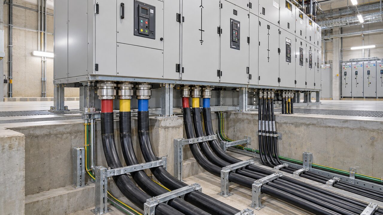
Substation cable gland acceptance should include the completed sealing interface, not just the visible gland body. Confirm that the required components are present and that the cable sheath at the seal is suitable for the approved installation. Record damaged parts, contamination or visible gaps for assessment under the applicable inspection criteria.
Use the manufacturer’s instructions for assembly sequence and any specified tightening requirements. A paint mark or a statement that the gland feels tight cannot establish compliance with those instructions. Where a recorded setting is required, retain the instruction reference, tool identification and completion record appropriate to the task.
Check unused entries against the approved closure arrangement. Temporary covers used during construction should not silently become permanent solutions. Identify entries reserved for later work, who owns their closure and whether their status prevents enclosure acceptance.
An enclosure’s declared ingress performance depends on its intended assembly and installation conditions. Do not assign a completed panel an ingress rating simply because a gland catalogue lists one. Ask the equipment supplier to define the evidence needed for the actual entry combination. Coordinate this review with the transformer kiosk condensation review, which addresses a related environmental concern.
Identify the required electrical function of each metallic gland and associated accessory. The approved design should explain how protective bonding, cable armour and any screen connection are handled. These functions should not be merged into a single unchecked box labelled earth complete.
Review the installed arrangement against that detail and retain the specified verification results. A photograph of a metal gland touching a metal plate does not, on its own, demonstrate the required electrical continuity. Conversely, adding an unplanned connection can conflict with the intended cable-screen arrangement.
Use a test record that identifies the circuit, points checked, method, instrument and acceptance basis. The qualified test team should determine the safe method and isolation conditions. This guide does not prescribe universal resistance limits or permit testing on an energized enclosure.
When an entry is dismantled or a cable is replaced after acceptance, assess which checks must be repeated. Update the record with the final assembly and close any superseded result. A previous pass should not be carried forward without considering the change.
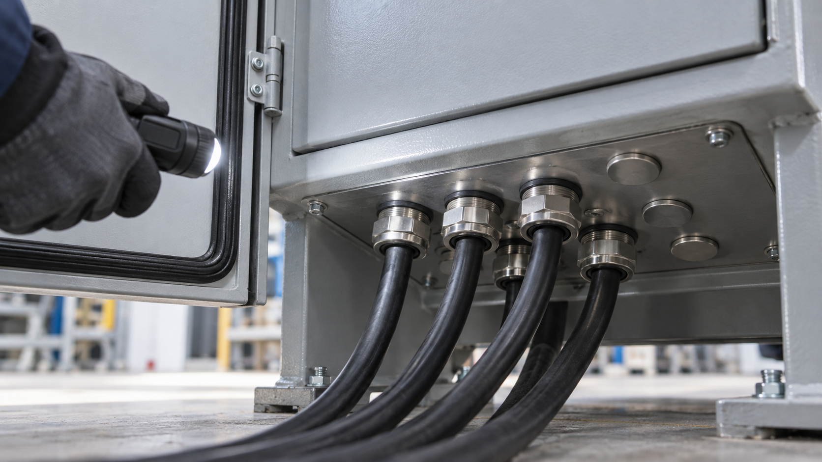
A compact register can include enclosure tag, entry reference, cable number, gland designation, instruction revision, inspection date, result and supporting photograph references. Add a clear status such as accepted, held for correction or awaiting installation. Avoid a blank cell that could mean either not applicable or not inspected.
Photograph the overall enclosure for location context and the relevant entry for detail. Keep the image reference tied to the register. Where a feature becomes hidden after assembly, agree the required witness or record point before installation. The purpose is to capture meaningful evidence, rather than a large collection of unlabelled close-ups.
Give each discrepancy an owner, corrective action and closure requirement. A replacement gland should trigger a new identity and compatibility check as appropriate. A repaired plate or revised adapter arrangement should be assessed against the updated design, not just the original photograph.
Carry unresolved items into the system turnover decision with their effect on readiness clearly stated. Substation cable gland acceptance is one part of enclosure completion; it does not replace protection testing, electrical safety checks or the formal authorization to energize.
In a hypothetical project, a cable substitution retains the conductor size but changes the outer sheath diameter. The site already holds glands selected for the earlier cable. The inspector records the mismatch and holds the affected entries while engineering and the supplier confirm the correct gland assembly. Revised material identity, drawings and inspection results are then linked to the release record.
This example is illustrative, not a Zisheng project claim. It shows why the actual cable and complete gland designation belong in the acceptance package. Substation cable gland acceptance should remain traceable even when purchasing descriptions appear unchanged.
No. It supports the product within its stated scope. Installed acceptance also needs the correct cable, entry interface, accessories and completion evidence required by the project.
Only the authorized acceptance process can determine the permitted status. Identify temporary closures explicitly and obtain the approved final arrangement before treating the enclosure as complete.
No. Follow the instructions for the specific product and assembly. Do not apply one generic value across different gland sizes, materials or accessory arrangements.
For a project discussion, provide the enclosure drawings, cable schedule, actual cable construction, gland data, required environmental performance and bonding detail. Include photographs and a list of unresolved entries. Zisheng Electric can use those inputs to clarify the equipment interface and the evidence required from each responsible party before handover.

Plan substation circuit breaker timing acceptance with clear trigger definitions, measured coil voltage, travel records and traceable native files. Review limits, retest history and control interfaces before EPC handover.
View details
Plan substation time synchronization acceptance with clock-source records, endpoint checks, event-time comparisons, loss-of-sync behavior and controlled EPC handover evidence.
View details
Plan substation relay settings handover: check approved files, relay identity, active groups, readback comparisons and changes before EPC closeout.
View details
Plan a substation water ingress walkdown for EPC handover: inspect roof drainage, thresholds, cable penetrations, trenches and electrical enclosures; assign repairs and release evidence.
View details