 zishengelectric



news
News Center
Providing high-quality power to the world
Search productSearch post
news
Providing high-quality power to the world
Control-cable screens are easy to overlook because they do not carry the main protection or control current. Yet an inconsistent shield termination can introduce noise, circulating current, false indications or an EMC problem that appears only after energization. Zisheng Electric treats substation control cable shield earthing handover as a traceable interface between design, panel manufacture, cable installation and commissioning—not as a final visual check.
The handover objective is not to prove that every shield is bonded at one end. It is to prove that each cable follows the approved project philosophy for its circuit, length, routing and electromagnetic environment. Instrument circuits, low-level analog signals, digital communications and multicore control cables may not share the same termination rule. The drawings, equipment manuals and utility specification remain the governing documents.

A cable schedule may state only “screened cable,” while the termination drawing shows the actual bonding arrangement. During construction, installers can cut a shield short, bond it to a gland plate by habit, leave a drain wire floating, or create an unintended second connection through a device chassis. A panel can therefore look neat while violating the approved EMC concept.
IEC 61000-5-2 gives guidance on earthing and cabling for electromagnetic compatibility. Project teams should confirm the applicable edition and combine it with the protection, control and communication equipment manufacturers’ instructions. High-frequency interference, power-frequency induction and safety earthing do not behave identically. A rule that is suitable for one signal type should not be copied across the entire substation without engineering review.
| Handover item | Evidence to capture | Decision supported |
|---|---|---|
| Cable identity | From/to equipment, cable tag, core use and route | Confirms that the record applies to the installed circuit |
| Approved philosophy | Bonding end or ends, termination method and drawing reference | Prevents field habit from replacing the design decision |
| Physical termination | Earth bar or gland point, clamp type, drain wire and insulation treatment | Shows whether the installation is durable and electrically intentional |
| Continuity result | Method, instrument, measured value or pass criterion, and test date | Demonstrates a continuous path without relying only on appearance |
| Isolation result | Check at the end intended to remain unbonded, where applicable | Detects accidental contact through glands, armour or chassis |
| Deviation status | Redline, concession, corrective action and closure approval | Keeps unresolved interfaces out of the final handover package |
The design team should issue a cable-screen matrix before site work begins. It should group circuits by function and identify the required termination at each end. It should also distinguish screen, armour, drain wire, spare cores and protective conductor. If a cable has more than one metallic layer, the drawing must show which layer is connected where. Ambiguous phrases such as “earth as required” are not installable instructions.
For some low-frequency, low-level circuits, bonding the shield at one designated end can avoid power-frequency circulating currents. However, high-frequency performance may benefit from low-impedance bonding at both ends or from equipment-specific arrangements. Long routes, mixed voltage systems, lightning exposure and digital communication interfaces require specialist review. The handover team should verify compliance with the approved design, not decide the philosophy at the panel door.
The project earthing interface also needs to be consistent with the wider station design. Review transformer earthing interfaces for EPC projects together with the control-cable philosophy so that panel bars, marshalling kiosks and equipment frames connect to the intended earthing network.
Add columns for screen type, termination end, terminal or earth-bar reference, drawing number and inspection status. Where the device manual requires a dedicated clamp or a maximum unshielded length, record that requirement in the termination detail. Avoid long pigtails for high-frequency bonding unless specifically approved; their inductance can reduce shielding effectiveness. Use clamps, glands and bonding hardware suitable for the cable construction and environmental duty.
Inspection begins with safe isolation and an approved test procedure. Sensitive electronic equipment may need to be disconnected or protected before continuity or insulation tests. The commissioning team must not apply a test voltage that exceeds the connected device’s withstand capability. The method statement should identify exclusions, temporary links and restoration steps.
At each panel or kiosk, confirm cable tag, gland entry, armour bond, shield preparation, drain wire, ferrules and earth-bar connection. Check that the exposed shield is minimized and mechanically supported. Verify that paint, corrosion, loose hardware or insulating washers do not interrupt an intended bond. At an intentionally isolated end, confirm that the screen cannot touch the gland plate, enclosure or spare cores during normal movement.
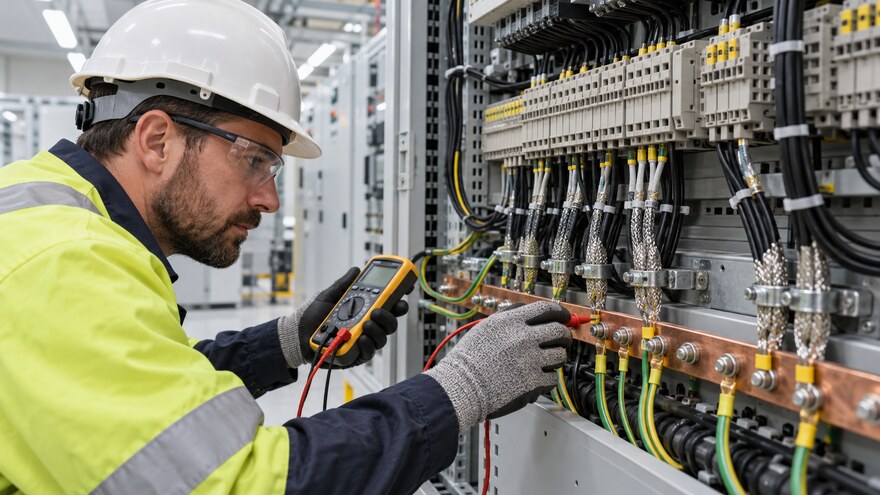
A continuity result is useful only when the test path is defined. Record where the instrument leads were connected and which parallel paths were removed or acknowledged. A simple low-resistance reading may be influenced by armour, panel bonding or another cable screen. The test sheet should therefore state the cable tag and the endpoints, not merely “screens checked.”
Where the approved philosophy requires a shield to be isolated at one end, verify isolation from the local gland plate and earth bar after the cable is fully dressed. Where bonding at both ends is required, confirm each physical connection and the continuity of the metallic path. If acceptance values are specified by the project, record them exactly. If no numeric criterion exists, obtain one from the responsible engineer rather than inventing a threshold during commissioning.
Temporary construction earths, test leads and panel jumpers can mask an open bond or create an apparent second bond. The test procedure should identify them and restore the final configuration before recording results. Also examine cable armour, metallic conduit and connector shells. These elements can create a return path even when the drain wire is deliberately isolated.
Coordinate the work with protection and control testing. The EPC protection and control interface matrix helps align cable tags, terminals and signal ownership, while the trip-circuit supervision acceptance review shows why final-state verification matters after temporary commissioning links are removed.

Substation control cables cross several supply boundaries. A switchgear vendor may terminate one end, the transformer supplier another, and the EPC cable contractor the route between them. Each party can meet its own scope while leaving the complete screen path undefined. The interface matrix should assign responsibility for cable supply, gland, screen clamp, earth-bar connection, inspection and test record at both ends.
Outdoor marshalling kiosks add moisture, condensation and corrosion risks. Ensure shield clamps and bars remain accessible after gland plates and internal wiring are complete. Confirm enclosure bonding, door earth straps and gland-plate continuity where these are part of the design. Cable support and cleating should prevent mechanical load on delicate screen terminations; the principles in substation cable cleat acceptance support this mechanical review.
Ethernet, serial links, process-bus networks and instrument circuits can have connector- and equipment-specific screen requirements. Follow the approved network design and vendor manual. Do not replace a manufacturer-approved connector with an improvised drain-wire connection. Fiber-optic cables avoid some conductive coupling paths, but their metallic armour or strength members may still require a defined treatment.
Zisheng Electric can coordinate control-cable interfaces with custom 380–660 V low-voltage switchgear, 3–10 kV medium-voltage switchgear and a project-specific 35–46 kV power transformer. Final terminal, cable and earthing arrangements must follow the approved project drawings.
The handover dossier should connect every record to controlled documents. Include the approved shield-earthing philosophy, cable schedule, termination drawings, panel and kiosk schematics, inspection checklists, test sheets, instrument details, calibration status, redlines, photographs where permitted, deviation records and as-built revisions. A summary sheet can show progress, but it should not replace circuit-level evidence.
Photographs are useful when they show the cable tag, termination point and nearby reference, but they are not electrical tests. Avoid generic panel photographs with no traceable identity. If the project restricts photography, use signed inspection records and marked-up drawings. The quality plan should define witness and hold points before covers or wireways conceal the work.
Use a consistent document numbering system across field sheets and the master cable schedule. The final index should identify superseded records and the latest approved revision, allowing the owner to retrieve the termination evidence without searching several contractor files.
Typical exceptions include an unintended bond at the isolated end, a screen cut too short, a loose clamp, an unidentified drain wire, a missing earth-bar link, a cable type different from the approved schedule or a vendor instruction that conflicts with the project drawing. Raise the discrepancy to the responsible engineer. The correction may require a termination repair, a drawing revision or an approved deviation; it should never be closed only by changing the test sheet.
Before handover, perform a final restoration check. Confirm temporary links are removed, disconnected device plugs are restored, cabinet covers are fitted, cable entries are sealed and all records show the final configuration. Link the outstanding-items list to energization readiness so that open shield-earthing issues cannot disappear in a general punch list.

Ask whether every screened cable has a defined termination philosophy; whether both ends have been inspected; whether the continuity path is unambiguous; whether the intended isolated end is actually isolated; whether vendor instructions are reflected in the drawings; and whether test equipment was suitable for connected electronics. Check that panel, kiosk and field-device responsibilities meet at the same cable tag.
Also ask whether as-built documents reflect approved changes, whether exceptions are technically closed, and whether maintenance personnel can identify the intended bond without repeating the commissioning investigation. A clear label and cable schedule reduce the chance that a future modification adds a second earth by mistake.
A dependable substation control cable shield earthing handover proves more than continuity. It demonstrates that the installed termination matches an approved, circuit-specific EMC design; that both bonded and isolated ends have been checked safely; and that the final state is traceable through drawings and records.
For project review, provide Zisheng Electric with the single-line diagram, control and protection schematics, cable schedule, panel drawings, termination details, equipment manuals, load list, technical specification, grid parameters, environmental conditions and installation-site constraints. Identify the governing utility requirements and the circuits with special EMC or communication needs. Our engineering team will review the requirements and respond to project inquiries within 24 hours.

Coordinate transformer fire protection interfaces for EPC substations, including fire walls, oil containment, detection, suppression, breaker trips, SCADA, integrated testing and handover evidence.
View details
Plan a transformer first-service thermal survey with safe access, representative load records, cooling checks, evidence ownership and clear EPC handover decisions.
View details
Plan substation cable penetration firestopping through an EPC checklist for opening geometry, tested systems, cable supports, inspections and handover evidence. Coordinate transformers and switchgear with Zisheng Electric.
View details
Reconcile substation asset tags with approved equipment schedules, nameplates, drawings, FAT records and commissioning evidence. Use discrepancy classes, owner-controlled data rules and traceable closeout actions to build a usable EPC handover reg...
View details