 zishengelectric



news
News Center
Providing high-quality power to the world
Search productSearch post
news
Providing high-quality power to the world
A drawing can show the correct alarm or trip destination while the electrical interface remains unsuitable. Zisheng Electric enquiries involving transformer accessories and switchgear controls therefore benefit from a circuit-level review before panel drawings are released. The small relay between two packages deserves the same attention as the equipment at either end.

This article is for EPC electrical engineers coordinating transformer marshalling cabinets, protection panels and switchgear. It addresses interposing relay selection and interface evidence, rather than protection settings. The objective is a signal path that works across the approved DC supply range and returns to the correct state after the command disappears.
Choose a representative circuit and trace it from its source contact or electronic output through terminals, supply protection, cables, interposing coil and destination contacts. Mark the boundary between each supplier. Ask who supplies the relay, who approves its duty and who tests the complete path. A component described only as “110 V DC auxiliary relay” leaves several important questions unanswered.
Record the exact relay and socket reference, coil version, suppression accessory, contact arrangement and circuit revision. Similar-looking plug-in relays can have different contact materials or coil characteristics. Substitution should trigger an interface review, not merely a purchasing description change.
Use the broader transformer protection interface matrix to assign package responsibilities. The relay review then provides the detailed evidence for an individual boundary in that matrix.
A headline current rating is not a complete switching assessment. The receiving load may be a relay coil, a breaker trip coil or a low-current digital input. Those duties need different checks. Request the manufacturer’s applicable making, continuous and breaking ratings at the actual voltage and load characteristics. Where a rating uses a time constant or utilization category, retain that condition in the review record.
The Finder 39 Series technical data, for example, distinguishes DC breaking capability from its AC contact rating and warns that a parallel diode on an inductive load increases release time. This illustrates why a catalogue headline should not be transferred to an unrelated circuit. It is not a recommendation that this relay family is suitable for every substation trip duty.
For a low-current input, request the minimum switching-duty information and the input’s wetting voltage or current requirements where applicable. For an inductive circuit, request the actual load characteristic and suppression arrangement. A component may satisfy the thermal duty while lacking suitable evidence for interruption or reliable low-level signaling.
| Interface question | Evidence from the packages | Design consequence |
|---|---|---|
| What does the contact switch? | Load identity, voltage, current and duty | Select against the actual load, not a generic ampere value |
| Can the coil operate at the receiving terminals? | Supply range, circuit drop and coil operating limits | Check the lowest credible operating condition |
| Will the coil release correctly? | Suppression circuit and guaranteed release behavior | Confirm reset and sequence timing |
| What happens on supply failure? | Healthy-state logic and loss-of-supply indication | Prevent an ambiguous healthy indication |
| How is the completed path proven? | Test boundaries, expected states and recorded timing | Close the interface with repeatable evidence |
Nominal battery voltage is a starting point. The design review should identify the approved minimum and maximum DC system voltages, circuit protective devices, cable route and any intentional series components. Compare the calculated coil-terminal voltage with the selected device’s guaranteed operating range. Use the project battery and cable calculations rather than inventing a universal voltage margin.
Consider a hypothetical 110 V DC interface. The approved minimum source voltage for this example is 99 V. If the complete outgoing-and-return circuit resistance is 20 ohms and the coil current at the review condition is taken as 0.05 A, the estimated cable drop is 1 V. The approximate receiving voltage is therefore 98 V. These assumed values illustrate the arithmetic only; the final calculation must use the selected coil’s behavior and all relevant series drops.
The review decision is not “98 V is always acceptable.” It is whether 98 V lies within the manufacturer’s guaranteed operating conditions for that exact assembly, with the project’s required margin and temperature basis. An unresolved operating limit belongs on the design action list before manufacture.
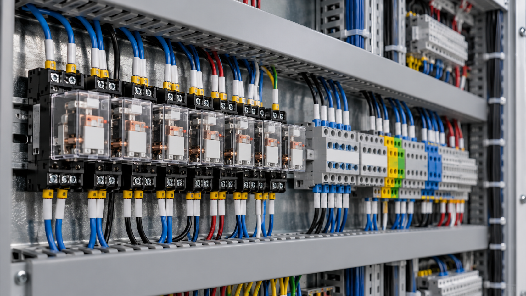
A suppression component is part of the functional circuit. Specify where it is installed and whether it is integral to the relay or socket. Record polarity and replacement restrictions. If a spare module uses a different suppression arrangement, maintenance may inadvertently change the release behavior even when the coil voltage matches.
Ask the protection or control engineer which transition matters: pickup, dropout, pulse duration, reset or sequence completion. Allocate timing across the source output, interposing device and destination equipment. Where timing is critical, define a measured acceptance criterion from the approved functional design. Do not infer an end-to-end guarantee by adding unrelated typical catalogue times.
A latching relay also requires a clear reset philosophy. Identify the reset command, indication, power source and behavior after loss and restoration of supply. The operator needs a meaningful state, not only a coil symbol that has been copied from another panel.
Prepare a test sheet that starts from the approved schematic revision. Record the source action, relevant supply condition, relay response, destination response and final restored state. Include negative cases that matter to the design, such as a missing supply or a removed control command. Testing must follow the authorized isolation and commissioning procedure; a convenient terminal bridge is not a substitute for a controlled test boundary.
Coordinate these records with trip-circuit supervision acceptance where the interface participates in a trip path. A relay operation recorded locally does not establish that the intended downstream device received the command. Conversely, a downstream indication alone may leave the initiating circuit unproven.
The bill of materials should reference the approved relay, socket, suppression and any required contact arrangement. Attach a substitution rule: replacement devices need equivalent demonstrated duty, operating limits and timing for the actual circuit. Keep the approved data with the final drawings so the maintenance team can purchase a compatible spare years later.
For a package using medium-voltage switchgear, provide the transformer accessory schedule and control schematic together. Zisheng Electric can review the requested supply boundaries and device interfaces against the proposed equipment scope. Include the DC voltage range, signal list, load duties and functional test expectations in your engineering enquiry.
Review the substation surge arrester interface for EPC projects: insulation coordination, placement, lead and earth paths, procurement boundaries, installation checks and documented handover.
View details
Review transformer pressure relief discharge routing through device selection, pipe supports, containment interfaces, site assembly and EPC handover records.
View details
Review a substation sump pump specification for hydraulic duty, standby capacity, power loss, level alarms and EPC handover.
View details
Coordinate transformer earthing interfaces for EPC projects: tank bonds, neutral grounding, core links, cable screens, surge arresters, FAT and handover.
View details