 zishengelectric





news
News Center
Providing high-quality power to the world
Search productSearch post
news
Providing high-quality power to the world
The main transformer can be correctly rated while its cooling controls, panel heaters or tap-changer drive remain incompatible with the station auxiliary supply. That mismatch is usually found at a terminal strip, not on the main nameplate. For Zisheng Electric enquiries, a transformer auxiliary power specification should be treated as a defined EPC interface before the marshalling cabinet is designed.
This article concerns the small power supplies that keep transformer accessories available. It is not a protection-setting guide or an instruction for live electrical work. The objective is to give the transformer supplier, station-service designer and commissioning team the same answer to four questions: what needs power, where it comes from, what happens if it fails, and how the interface will be accepted.
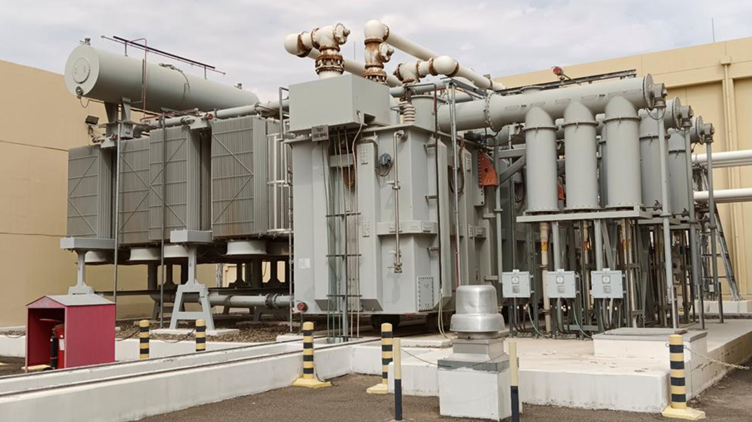
List the actual accessories included in the package. Depending on the design, these may include cooling fans, oil pumps, motor-drive equipment, temperature instruments, monitoring devices, cabinet lighting and anti-condensation heaters. Do not copy a generic list into every enquiry. A naturally cooled distribution transformer and a large forced-cooled power transformer have different auxiliary requirements.
Give every load an equipment tag and record its supply type, rated input, acceptable operating range and duty. Distinguish continuous consumption from motor starting or brief operating demand. A total wattage at the bottom of a spreadsheet is not enough to size a supply circuit when several motors can start together.
At Zisheng Electric, the useful engineering-review question is whether each accessory has an identified source and a named interface owner. “Auxiliary supply by EPC” leaves the voltage, cable boundary, protective device and commissioning responsibility unresolved. Replace that sentence with a schedule that can be checked against the cabinet schematic.
| Auxiliary load | Main interface risk | What should be confirmed |
|---|---|---|
| Cooling fans or pumps | Supply supports running load but not the intended starting sequence | Motor data, grouping, starting demand, protection and loss-of-cooling response. |
| Tap-changer motor drive | Motor, control and heater circuits are assumed to use one common supply | Actual equipment diagram, circuit voltages and required protective arrangement. |
| Monitoring instruments | Device loses power during the event it should report | Source continuity, restart behavior and loss-of-supply indication. |
| Panel heaters | No permanent supply is available during storage or construction | Preservation method, heater supply and responsibility before energization. |
| Cabinet service circuits | Convenience loads share an essential circuit without review | Segregation, ratings and maintenance isolation boundaries. |
| Remote indications | Dry contacts are confused with powered signal inputs | Contact ratings, wetting supply and terminal ownership. |
Write AC or DC next to every voltage value. For AC circuits, include phase arrangement and frequency. For DC circuits, identify polarity and the project earthing arrangement. Do not assume that the marshalling cabinet uses the same nominal voltage as the station battery or the nearby low-voltage board.
A device may have separate motor, control and heater circuits. Its product name alone does not establish their ratings. Obtain the offered accessory’s nameplate data and approved wiring diagram, then reconcile them with the station supply schedule. An alternative component should undergo the same check even when it performs the same apparent function.
A potential-free contact switches an externally provided circuit; it does not generate the voltage required by the receiving system. Confirm which party provides the wetting supply, the contact’s applicable AC or DC switching rating, and the receiving input requirements. A contact suitable for one duty is not automatically suitable for another merely because the nominal voltage matches.
Keep this power-source review distinct from the full transformer protection interface matrix. That matrix coordinates protection and signals. The auxiliary schedule establishes what supplies the devices and whether the intended functions remain available when a source is lost.
The station designer should decide which functions can tolerate interruption and which require a more secure source. That decision depends on the project operating philosophy, not on a universal rule that every accessory belongs on DC or on an uninterruptible supply. Confirm the consequence of losing each source and the acceptable recovery behavior.
For a power transformer package, cooling supply loss may affect the available loading capability, while monitoring power loss may remove information without stopping the main power path. Those are different consequences. Record the required alarm, operator response and any engineered operating restriction in the approved documents.
Preservation is another duty. The main transformer may remain unenergized for months while its cabinets still require environmental protection. Decide who provides temporary power, who checks the preservation condition and how temporary arrangements are removed before final handover. A shipping release does not transfer these tasks automatically to a named site team.
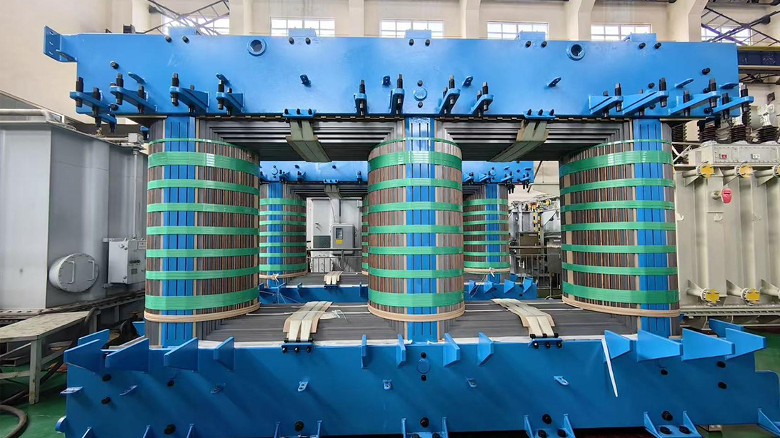
Where forced cooling is supplied, ask for the number of fans or pumps, motor ratings, grouping and control sequence. Separate the command to run from evidence that the equipment is operating. A contactor command alone does not prove airflow or oil circulation. Specify the feedback that the actual design provides and avoid claiming monitoring functions not included in the package.
Review the source and outgoing circuit for the intended starting duty. Cable length, protective devices and motor-starting behavior need a coordinated electrical assessment. Do not choose a protective rating solely by adding steady-state currents or increase a fuse rating at site to suppress repeated trips without engineering approval.
The permitted loading after a cooling-stage failure must come from the transformer’s approved design and operating guidance. It cannot be inferred from the number of fans that remain available. Do not assume that half the fans means half the rating, or that a forced-cooled unit can continue indefinitely at its full rating without auxiliaries.
Document alarm priorities, operator instructions and any automatic action required by the project. If cooling has redundant sources, describe the transfer arrangement and how a failed source is identified. The presence of two incoming cables does not prove that the complete cooling system has independent redundancy.
An anti-condensation heater is easy to overlook because its power is small. Its purpose is different from cooling the transformer or heating the oil. Confirm the device rating, control arrangement, required supply availability and the manufacturer’s instructions for storage and operation.
Manufacturer instructions can impose specific preservation requirements. For example, Reinhausen’s published VACUTAP operating instructions address condensate damage in the motor-drive housing and the use of its heater during operating interruptions. The correct procedure depends on the supplied model. Do not transfer a time interval or heater rating from one product to every transformer cabinet. Manufacturer reference: VACUTAP operating instructions.
For outdoor EPC installations, ask the site team to define actual humidity exposure, storage duration and availability of temporary services. A sealed shipping cover is not evidence that cabinet preservation can be ignored. Record the approved alternative if the specified supply cannot be provided; do not improvise inside an electrical enclosure.
The supplier should identify incoming terminals, cable-entry provisions, protective-earth connections and the internal circuits served by each source. The EPC designer should identify the outgoing board, feeder designation, cable specification and isolation method. Match terminal numbers across the schematic, cable schedule and installation drawing.
A low-voltage switchgear package may form part of the station-service arrangement, but its product voltage range does not determine every accessory supply. Where another voltage or supply type is required, define the appropriate source equipment and its ownership in the project design.
Pay attention to multiple sources entering one cabinet. Turning off one isolator may not remove every hazardous supply. The approved drawings and labels should identify the isolation boundaries clearly. Installation, testing and maintenance require qualified personnel using the site’s electrical safety procedures; this interface review is not a switching instruction.
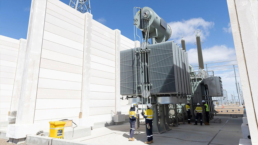
Factory acceptance should include the relevant auxiliary functional checks in the agreed scope. Identify the test source, supply conditions, expected indications and acceptance evidence. A general statement that the transformer passed electrical tests does not demonstrate every alarm, selector position or cooling-control function.
Use the transformer inspection and test plan to allocate witness requirements and records. List any simulation explicitly. A simulated input can demonstrate part of a control path, but it does not necessarily prove the field sensor, installed cable or remote receiving system.
| Verification item | Common gap | Required record |
|---|---|---|
| Accessory supply ratings | Offer and installed component differ | Nameplate and drawing comparison against the approved schedule. |
| Cooling control | Command operates but feedback is not checked | Agreed operating sequence and actual feedback observations. |
| Source-loss indication | The alarm disappears with its own supply | Functional result for the defined source-loss condition. |
| Local and remote modes | Conflicting commands or unclear selection | Approved mode logic and tested command boundaries. |
| Heater circuit | Component is present but preservation responsibility is missing | Electrical check and documented storage arrangements. |
| Site completion | Factory simulation is treated as a complete installed test | Open interface list and site end-to-end verification responsibility. |
Where the procedure includes loss-of-supply or restart tests, agree the method and equipment limitations with the manufacturer beforehand. Do not interrupt a motor drive at an arbitrary point to see what happens. The test must be appropriate to the supplied equipment and performed under an approved safe procedure.
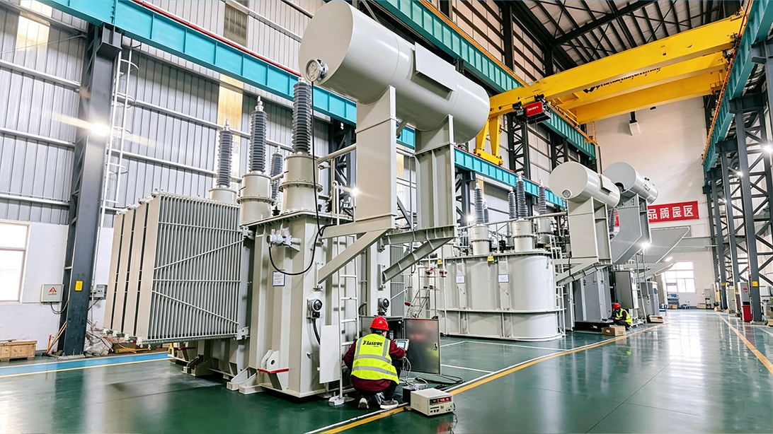
Before final acceptance, confirm that the permanent source matches the approved supply and that temporary cables or links have been dealt with through the site procedure. Reconcile field labels, drawings and test records. Confirm that the remote system receives the intended indications rather than accepting a local lamp as end-to-end proof.
Keep an open-item list with an owner and closure evidence for each unresolved point. Separate a missing document from a failed function: both need attention, but they may have different consequences for readiness. The responsible project authority should decide whether the outstanding item affects energization or handover.
After handover, changes to a station battery, auxiliary board, motor drive or monitoring device can reopen the interface. Compare the new component’s supply and contact requirements with the existing circuit. Update the drawings and relevant operating instructions; a successful physical replacement does not establish electrical compatibility.
For a transformer auxiliary power specification, send Zisheng Electric the station AC and DC supply data, single-line diagram, accessory list, cooling duty, control philosophy, cable boundaries and preservation requirements. Identify the parties responsible for station services, transformer controls and site commissioning.
Zisheng Electric can provide technical matching for power transformers and related distribution equipment against the project capacity, voltage, environmental conditions and technical specification. Our engineering team will review the requirements and respond to project inquiries within 24 hours.

Control transformer design changes across EPC drawings, electrical studies, physical interfaces, manufacturing and acceptance. Define owners, evidence and release gates.
View details
Oil immersed transformers are used in power transmission and distribution systems where reliable voltage conversion is required. The transformer core and windings are submerged in insulating oil, which provides both electrical insulation and heat ...
View details
Plan transformer seismic qualification for substations with site spectra, structural evidence, anchorage coordination, accessory checks and documented site release.
View details
Power infrastructure across Saudi Arabia, the UAE, Qatar, and Oman operates under conditions that would quickly derate or destroy standard electrical equipment. In these environments, transformer failure is rarely a manufacturing defect—it is almo...
View details