 zishengelectric



news
News Center
Providing high-quality power to the world
Search productSearch post
news
Providing high-quality power to the world
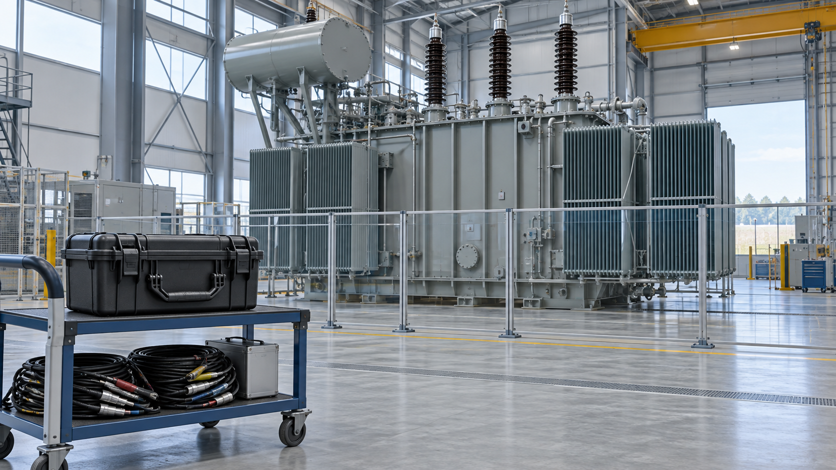
When a transformer reaches site, an insulation-resistance reading is useful only if the test boundary and environmental conditions are recorded with it. Zisheng Electric encourages EPC commissioning teams to agree those details before mobilization, so the baseline can be compared meaningfully with factory or later maintenance records.
This guide is for commissioning engineers and owner representatives preparing a de-energized field test before energization, after transport, or following agreed maintenance. It explains what to record, how to keep the sequence safe, and when a result needs engineering review. It does not prescribe a universal pass value: transformer design, insulation temperature, configuration and the governing project criteria matter.
Insulation resistance testing applies a controlled DC voltage between selected windings and earth, or between winding groups, then records resistance over an agreed time. The measured value depends on the insulation system and its condition, but also on temperature, moisture, surface contamination, connections, test voltage and instrument range. A single number without this context is difficult to trend and easy to misinterpret.
IEEE Std C57.152-2025 provides guidance for diagnostic field testing of liquid-immersed power transformers and related equipment. It treats field measurements as diagnostic evidence that should be interpreted with the equipment manufacturer’s guidance and other relevant tests. The project team should confirm the contractually applicable edition, test method and acceptance authority before issuing a method statement.
Start from the approved single-line diagram, winding connection drawing and transformer manual. Identify which winding-to-ground and winding-to-winding combinations are included, which bushings and accessories must be isolated, and how the remaining terminals will be guarded or grounded. Control induced voltage and backfeed risks from connected circuits. The approved site isolation and lockout procedure governs the work; a resistance test is never a reason to relax it.
| Record item | Why it matters | Review question |
|---|---|---|
| Unit identity and winding pair | Links the reading to the correct asset and test boundary | Do serial number, drawing revision and terminal labels agree? |
| Test voltage and duration | Defines the measurement method and comparability | Was the level selected from the OEM procedure and project method? |
| Temperature and humidity | Provides context for changes in insulation resistance | Were winding/oil temperature and ambient conditions recorded at the time? |
| Time-stamped readings | Shows the resistance trend during the application | Are the instrument readings and elapsed times preserved, not just a final value? |
| Instrument and connections | Supports traceability and troubleshooting | Are serial number, calibration status, lead arrangement and guard use stated? |
Apply the site-approved isolation, prove-dead and grounding process. Identify all possible sources, including auxiliary supplies, connected buswork and induced voltage from adjacent energized circuits. Disconnect or isolate accessories only where the manufacturer and approved procedure permit it. Establish an exclusion zone and assign one person to control test leads and communication.
Record the actual tap position and configuration. Clean and dry external bushing surfaces where the approved procedure calls for it; surface leakage can affect readings. Connect the instrument to the specified winding pair, use guard terminals only as directed, and keep unused terminals in the prescribed state. Confirm the selected test voltage and instrument range against the OEM instructions and project work pack rather than choosing a value from a generic online table.
Record the initial resistance and agreed time points while the test voltage is applied. If the procedure calls for a polarization index, calculate it from the specified readings and state the time basis; do not report a ratio without the underlying values. Interpret the curve with temperature and construction in view. Some transformer designs or conditions make a simple index less diagnostic than it is for other insulation systems.
At the end of each measurement, discharge the tested winding using the instrument’s discharge function and the approved grounding sequence. Verify the residual voltage condition before changing leads. Record any interruptions, unstable readings, surface tracking, unexpected instrument behavior or retest. Keep original and repeat data together, with a clear note explaining which reading was used for disposition.
Compare the result first with the manufacturer’s acceptance guidance and any project-specific criteria. Then review it alongside prior measurements only when the test boundary, voltage, duration and temperature correction basis are compatible. A sudden change can justify investigation, but it does not identify a cause by itself. Moisture, contamination, connection condition, temperature, bushing surface leakage and test setup can all influence the result.
Do not treat insulation resistance as a substitute for dielectric, power-factor, oil or other diagnostic tests. If readings are low, unstable or inconsistent across phases, hold energization and request an engineering disposition from the manufacturer and owner’s technical authority. A repeat test may be appropriate after checking the setup, but repeating until a preferred number appears is not an acceptance method.
For related commissioning records, see the winding-resistance handover guide and bushing power-factor test guide. For equipment context, review Zisheng Electric’s 2500 kVA oil-immersed transformer and 35/46 kV power transformer.
Only when the test configuration, voltage, duration, temperature basis and instrument method are sufficiently comparable. Record the differences and obtain the manufacturer’s interpretation if they are not.
No single value should replace the project specification, manufacturer guidance and the applicable test method. The same measured resistance can mean different things under different conditions.
No. Energization requires completion of the full approved commissioning and safety checks, closure of open deviations, and authorization by the responsible project authority.
Before commissioning, ask Zisheng Electric to review the proposed test boundary, OEM criteria and record template with your EPC team. A well-documented baseline makes later comparisons more useful and keeps any acceptance decision tied to the actual transformer and contract.

Plan substation firestop handover with penetration registers, approved system references, staged inspection evidence and clear EPC release responsibilities.
View details
Build a transformer SFRA baseline package for EPC handover: align test configurations, preserve raw files and resolve comparison gaps before release.
View details
Plan substation emergency lighting handover with approved area boundaries, circuit schedules, source-failure tests, battery duration evidence, punch closure and operator maintenance records.
View details
Plan substation cable penetration firestopping through an EPC checklist for opening geometry, tested systems, cable supports, inspections and handover evidence. Coordinate transformers and switchgear with Zisheng Electric.
View details