zishengelectric





news
News Center
Providing high-quality power to the world
Search productSearch post
news
Providing high-quality power to the world
Zisheng Electric approaches commissioning high voltage switchgear as an integrated EPC verification process. A switchgear panel can pass factory tests and still be unsafe or unavailable at site if cable phasing is wrong, DC trip power is missing, interlocks do not match the operating philosophy, protection settings are not approved or SCADA commands address the wrong device. Commissioning must prove the complete operating chain, not only individual components.
This guide focuses on metal-enclosed switchgear used in substations and industrial distribution systems. “High voltage” is used in the project-search sense; the exact equipment class and applicable IEC 62271 parts must be confirmed from the rated voltage, construction and contract. The commissioning procedure must also follow the manufacturer’s manuals, approved switching rules, utility requirements and site safety system.
The boundary should identify every panel, bus section, circuit breaker, earthing switch, disconnector where applicable, instrument transformer, surge arrester, protection relay, meter, control switch, auxiliary supply, intertrip, communication link and remote-control point. It should also state which organization owns each test and who accepts the result. Without a boundary matrix, the switchgear supplier may test panel wiring while the EPC team assumes the protection contractor tested the complete trip circuit.
Prepare a system single-line diagram and an interface register before detailed procedures. Show normal and abnormal operating configurations, bus couplers, bus transfer, generator connections, transformer incomers, backfeed risks and temporary construction supplies. Commissioning sequences must consider all credible sources of energization.
Testing should not start from unapproved drawings. The minimum controlled set normally includes the single-line diagram, general arrangement, schematic and wiring diagrams, cable schedules, terminal plans, protection philosophy, approved relay settings, CT and VT schedules, interlock matrix, SCADA point list, communication architecture, AC/DC distribution drawings and manufacturer manuals. Record document revision on each test sheet.
Review factory test reports and outstanding punch items. A FAT report is useful only if the site team can map the tested panel number, breaker serial number, relay configuration and wiring revision to the installed equipment. If components were replaced after FAT, identify which tests must be repeated.
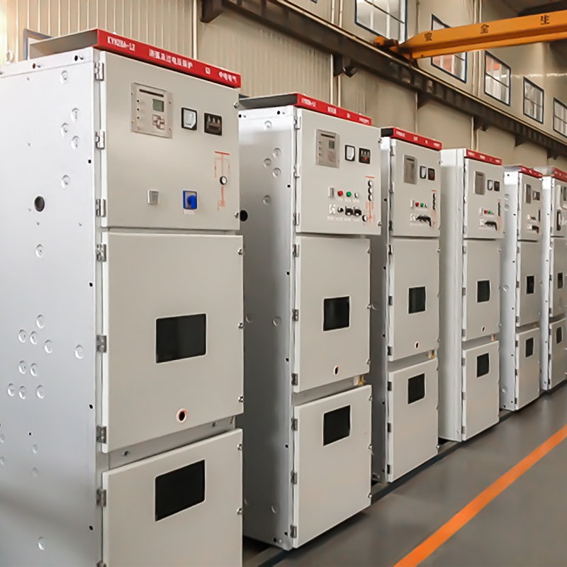
Confirm panel alignment, anchoring, bus-joint assembly, torque records, compartment cleanliness, transport-damage inspection, pressure indication where applicable, heaters, door operation, shutters, breaker racking and earthing-switch movement. Check labels against the single-line diagram and cable schedule. Shipping splits deserve special attention because bus connections, protection wiring and auxiliary supplies may cross the split.
Foreign material is a serious risk. Remove packing pieces, loose hardware, wire offcuts and cleaning residue. Inspect insulation surfaces using the manufacturer’s method. Do not use uncontrolled solvents or compressed air. Confirm that temporary earths and construction supplies are recorded and controlled before the energization boundary is established.
| Test group | Purpose | Typical interface | Release evidence |
|---|---|---|---|
| Mechanical operation | Prove breaker, shutters, doors and racking | Panel, breaker and operating mechanism | Operation record, position indication and punch closure |
| Electrical interlocks | Prevent prohibited operations | Local controls, hardwired logic and station control | Approved interlock matrix with pass/fail results |
| CT/VT circuits | Prove ratio, polarity, continuity and isolation | Switchgear, metering and protection packages | Point-to-point and injection records |
| Protection trip chain | Prove relay input through breaker opening | Relay, lockout, DC supply and trip coil | Secondary injection and end-to-end trip record |
| SCADA control | Prove status, alarm and command mapping | IED, gateway, network and control center | Point-to-point schedule with timestamps and command results |
| Insulation and main circuit | Confirm condition after transport and installation | Busbars, cables, instrument transformers and terminations | Approved test results with environmental conditions |
Use the approved interlock matrix to test both permitted and prohibited operations. Typical checks include breaker closing only in defined service or test positions, earthing-switch operation only when isolation conditions are met, racking restrictions with the breaker closed, door and shutter logic, bus-coupler permissives and electrical transfer schemes. The exact functions depend on the switchgear design and operating philosophy.
Negative testing is essential. Proving that a permitted command works does not prove that an unsafe command is blocked. Simulate each relevant position, power-supply state and remote/local selection. Record the initiating condition, expected response, actual response and final device position. If software logic contributes to an interlock, control its version and include failure-mode behavior.
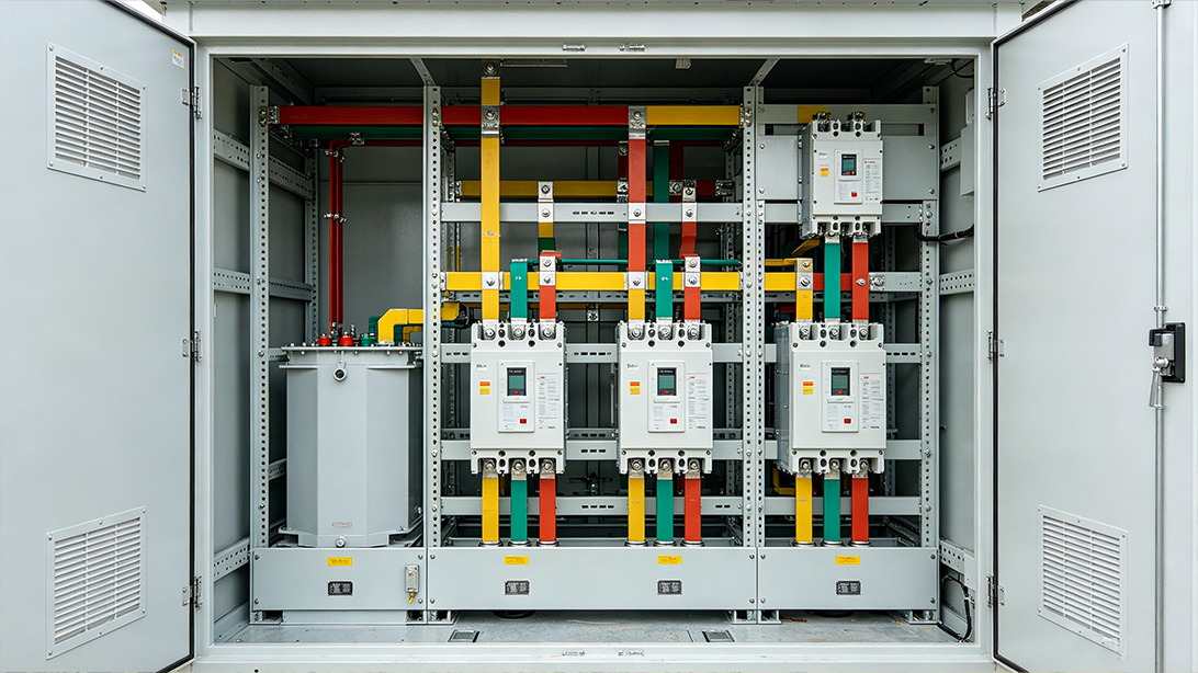
Start with CT and VT identity. Confirm ratio, polarity, core allocation, secondary earthing, terminal routing and shorting facilities. Trace each circuit from the primary device through terminals to the relay or meter. A correct relay setting cannot compensate for reversed polarity or a CT core connected to the wrong input.
Secondary injection should prove pickup, timing, logic outputs, indications and records. Where the project requires it, an end-to-end trip test should demonstrate the path from simulated protection input through relay logic, lockout or interposing relays, trip-circuit supervision and breaker opening. Confirm both trip coils if provided. Record DC voltage at relevant points and investigate excessive voltage drop.
Metering checks should compare phase quantities, direction and scaling. For incomers and generators, confirm active and reactive power direction under the intended reference convention. Incorrect sign conventions can affect operator decisions and automatic controls even when protection remains functional.
Prove AC heaters, lighting, sockets and mechanism supplies, plus DC control and trip supplies. Test changeover or redundancy if specified. Confirm miniature circuit-breaker labels, fuse ratings, alarms and selectivity assumptions. Loss of one auxiliary source should produce the expected alarms without creating unintended breaker operations.
SCADA testing should use the approved point list. Verify device name, bay designation, state, alarm priority, timestamp, quality flag, remote/local status and command select-before-operate behavior where applicable. Test communication failure and recovery. Commands must be proven with the operating authority’s permission and within a controlled test boundary.
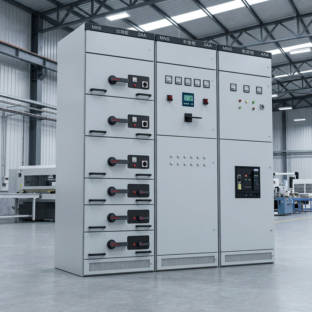
The project procedure should define insulation-resistance, contact-resistance, power-frequency or other field tests required for the specific equipment. Test voltage, isolation boundaries, connected equipment, discharge method, environmental conditions and acceptance criteria must be approved. Avoid applying a test intended for switchgear to connected cables, transformers, voltage transformers or surge arresters without confirming their suitability.
Contact-resistance results should be assessed by phase and by comparable joints, with attention to the measurement method and current. A single number without test location or baseline is difficult to use. Where gas or vacuum interrupting technology is involved, perform the manufacturer’s specified checks rather than inventing a generic field test.
Energization requires more than completed test sheets. Confirm that punch items are classified and closed, protection settings are approved and loaded, as-left files are backed up, temporary earths are removed under control, doors and covers are secured, remote control is coordinated, fire and access systems are ready, and operators have the current single-line diagram. The release certificate should identify the exact boundary and any restrictions.
Prepare a switching program with responsibilities, communication channels, hold points and abort criteria. After energization, observe voltage, phase sequence, relay measurements, abnormal sound, smell, discharge indications, heater and ventilation operation, and SCADA status. Load should be introduced according to the approved plan, with follow-up inspection after the first operating period.
Hypothetical example—not a real project: “Energization release shall not be signed until the approved interlock matrix has been tested, CT/VT circuits have been verified, final relay settings are loaded and recorded, trip circuits have passed functional tests, SCADA point-to-point checks are complete, temporary earths are controlled, and all Category A punch items are closed. The release shall identify remaining Category B items and operating restrictions.”
Commissioning changes the condition of equipment repeatedly. Test plugs are inserted, links are opened, relay outputs are blocked, temporary supplies are connected and interlocks may be placed in an approved test mode. Every temporary condition needs a register, an owner and a restoration check. A successful test followed by incomplete restoration can create a greater operational risk than an untested circuit.
Use the site permit-to-work, isolation and lockout system. Test equipment should have suitable ratings, calibration status and leads. Before each primary or dielectric test, confirm the boundary and connected equipment. After each test, discharge stored energy, restore normal connections and perform an independent check where required. The commissioning manager should be able to state which panels are safe, which are under test and which are released at any time.
The final dossier should contain relay setting files, logic and firmware references where contractually required, SCADA databases or point lists, test results, deviations, punch closure, breaker operation counts, calibration certificates and approved as-built drawings. Store both human-readable reports and native configuration files in the project document system. Screenshots alone are not a reliable configuration backup.
Record the as-left local/remote selectors, protection enable states, trip-circuit links, communication addresses and time-synchronization status. The operations team should receive a briefing on alarms, interlocks, switching restrictions and deferred items. If a future stage will extend the bus or add feeders, identify the reserved circuits and protection changes so that today’s commissioning record supports the next outage.
Zisheng Electric can coordinate commissioning high voltage switchgear with transformer, prefabricated-substation and EPC interface requirements. Review our EPC and project supply approach, custom engineering solutions, technical support and after-sales service, prefabricated substation products and transformer product range. Related project guidance includes the site assembly supervision plan and EPC acceptance planning example.
Confirm applicable editions in the official IEC catalogue: IEC 62271-1 search, IEC 62271-200 search and IEC 62271-100 search.
To support a project review, send Zisheng Electric the drawings, transformer or switchgear data sheets, load list, technical specification, single-line diagram, system parameters, environmental conditions and installation-site constraints. “Our engineering team will review the requirements and respond to project inquiries within 24 hours.”
Define transformer OLTC control interfaces for AVR measurement, raise-lower commands, tap position, parallel operation, FAT and commissioning.
View details
Transformer bushing specification guide for EPC substations covering rated voltage and current, insulation levels, creepage distance, CT terminal interfaces, dimensional checks, FAT evidence and commissioning acceptance.
View details
Plan substation arc flash study inputs for EPC projects: source fault data, transformer impedance, switchgear geometry, protection settings and as-left handover.
View details
Plan substation auxiliary power design with station-service transformers, AC/DC loads, batteries, transfer logic and commissioning checks.
View details