zishengelectric



news
News Center
Providing high-quality power to the world
Search productSearch post
news
Providing high-quality power to the world
At Zisheng Electric, an EPC transformer protection and control interface matrix is used to turn a complex equipment package into a testable boundary between the transformer supplier, EPC contractor, protection engineer and site commissioning team.
Interface problems rarely begin with a single wrong wire. They usually come from different drawing revisions, unclear signal ownership, missing terminal details or an assumed alarm that was never included in the relay or marshalling cabinet. A controlled matrix gives every signal a source, destination, terminal, normal state, test method and responsible owner.
Transformer protection includes differential, overcurrent, earth-fault, Buchholz, pressure relief, oil level, winding temperature and cooling alarms. The EPC system may also require breaker trip, lockout, breaker-failure initiation, SCADA status, remote tap position and fire protection interfaces. If these points are shown only on separate drawings, omissions can survive until FAT or site energisation.
The matrix establishes the agreed boundary. It records whether a contact is volt-free or powered, normally open or normally closed, maintained or pulsed, fail-safe or fail-to-alarm, and whether the signal is wired to a local panel, protection relay, RTU or control room.
| Interface group | Typical signals | Decision to freeze | FAT evidence |
|---|---|---|---|
| Transformer protection | Differential trip, earth-fault trip, lockout | Trip path and reset philosophy | Secondary injection and trip test |
| Mechanical alarms | Buchholz, pressure relief, oil level | Contact state and alarm priority | Contact simulation and cause-effect record |
| Cooling control | Fan start, fan failure, pump status | Automatic stages and standby logic | Sequence test and current record |
| Tap changer | Raise/lower, position, motor fault | Local/remote authority and interlock | Full tap travel and indication test |
| SCADA and metering | Breaker status, alarms, analogue values | Point naming, scaling and ownership | Point-to-point and database sign-off |
Start with the approved single-line diagram, protection philosophy, transformer data sheet, relay schedule, cable schedule, marshalling-box drawing and SCADA point list. Add the utility interface requirements and the owner’s alarm priority standard. Every document should carry a revision number. The matrix should identify which document governs when two drawings disagree.
For each point, define who supplies the contact, who supplies wetting voltage, who provides the cable, who terminates it and who tests it. A transformer supplier may provide a dry contact at the marshalling box, while the EPC contractor provides the multicore cable and the RTU cabinet. That boundary must be visible before manufacturing.
Record terminal number, wire number, cable core, shield treatment, spare core and segregation requirement. Protection trip circuits, CT secondary wiring, control power and communications may require different routing or shielding. The final terminal schedule should match the as-built cabinet, not an early quotation drawing.

The most critical interface is the trip path. Confirm whether transformer differential and mechanical protection operate a master lockout relay, trip the HV breaker directly, trip both sides, or initiate breaker failure. Define the DC voltage, coil supervision, reset method, test switch and interlock. A trip circuit that works during FAT but cannot be safely tested at site is not a complete design.
CT and VT interfaces need particular care. Verify polarity, ratio, class, burden, terminal shorting facilities and test links. The protection engineer should approve the CT schedule before secondary injection. Do not change a terminal arrangement to simplify wiring without checking the relay logic and test procedure.
Cooling logic should show the temperature or load condition that starts each fan or pump stage, the standby changeover, alarm delay and trip or derating response. The EPC team should know whether the transformer supplier or the site PLC owns automatic sequencing. The same principle applies to OLTC control: define local and remote authority, raise/lower commands, tap position feedback, motor protection and manual emergency operation.
During FAT, review the matrix line by line. Simulate protection trips, mechanical contacts, cooling failures, low oil level, charger failure, tap changer limits and communication loss. Record the source contact, receiving terminal, relay or PLC indication, alarm text, trip action and reset result. A screenshot without a terminal reference is weak evidence.

| Handover record | What it should prove | Owner sign-off |
|---|---|---|
| Approved interface matrix | All signal ownership and revisions are controlled | EPC / owner / supplier |
| Terminal schedule | Physical wiring matches drawings | Supplier / commissioning |
| Cause-and-effect test | Alarm and trip responses are correct | Protection engineer |
| SCADA point list | Names, states and scaling are correct | Control-system engineer |
| Deviation register | Open items have owners and closure dates | Project manager |
Zisheng Electric coordinates transformer configuration, protection interfaces, marshalling cabinets, tap-changer controls, FAT records and commissioning support as one project workflow. For an EPC transformer protection and control interface matrix review, send us your drawings, datasheets, load list, technical specification, single-line diagram, grid parameters and environmental conditions. Include the relay list, CT schedule, SCADA point list and utility interface standard where available. We will return a controlled action list and respond to project inquiries within 24 hours.
Related resources include our transformer datasheet approval guide, EPC project supply solution and 110kV/115kV power transformer.
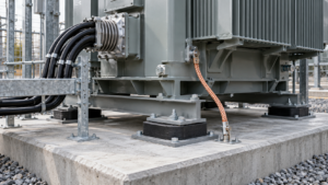
Plan transformer seismic qualification for substations with site spectra, structural evidence, anchorage coordination, accessory checks and documented site release.
View details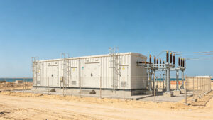
The questions we get asked most often when we visit the Middle East to communicate with customers about power distribution equipment are: Can your equipment withstand high temperatures? How fast can you deliver? Have you obtained the required cert...
View details
Plan transformer warranty handover for EPC projects with baseline records, defect triage, spares, notification routes and technical support interfaces.
View details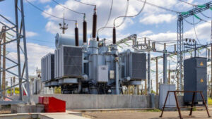
A practical EPC transformer cable schedule guide covering gland plates, MV and LV terminations, control wiring, FAT checks and site handover.
View details