zishengelectric





news
News Center
Providing high-quality power to the world
Search productSearch post
news
Providing high-quality power to the world
Transformer packages in EPC projects rarely fail because a transformer was simply unavailable. More often, the failure begins with an interface that was never closed. The primary voltage appears on the single-line diagram, the auxiliary supply is defined in a protection drawing, the cable-entry direction remains in a meeting minute, and the approved GA drawing still reflects a tender-stage assumption. At Zisheng Electric, we break an EPC transformer technical interface into controlled data, drawings, responsible parties, review status, and closure dates. That is how the transformer, switchgear, civil works, protection system, transport plan, and site team can work from one technical baseline.
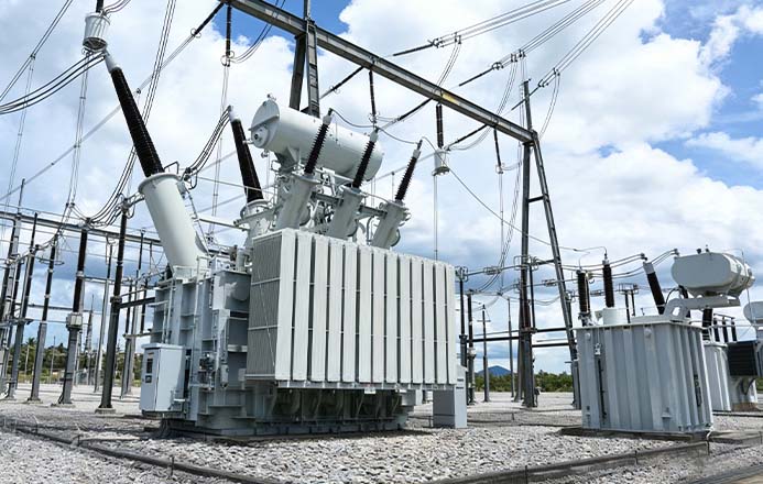
An interface record that only says “vendor to confirm” is not closed. A usable record has an input, owner, submission format, review code, due date, and list of affected downstream documents. A bottom-entry high-voltage cable, for example, affects more than the transformer terminal. It changes the foundation opening, cable bending radius, cleats, earthing arrangement, and installation sequence.
When a closed interface changes, the project needs a controlled change number. The EPC team should then trace whether the GA drawing, bill of materials, purchase orders, civil drawings, cable schedule, and site method statement have been updated. Without that trace, a technically correct meeting decision can still become a site rework.
| Interface Package | Typical Lead | Items to Freeze | Affected Documents |
|---|---|---|---|
| Primary system | EPC electrical design | Rating, voltage, vector group, impedance, earthing | SLD, datasheet, load-flow and fault studies |
| Mechanical and civil | Vendor / EPC civil | Dimensions, weights, rails, foundation, oil pit, clearances | GA, foundation drawing, lifting plan |
| Protection and control | Protection engineer | CT data, alarm and trip contacts, terminals, protocol | Schematics, terminal plan, I/O list, settings |
| Procurement and delivery | Project procurement | Scope boundary, spares, documents, milestones | MR, PO, MDR, manufacturing schedule |
| Site construction | Construction manager | Transport, unloading, assembly, oil treatment, testing | Method statement, ITP, commissioning records |
The transformer datasheet should define rated power, all winding voltages, highest system voltage, frequency, phases, vector group, impedance, insulation levels, tapping method, losses, temperature rise, and cooling mode. Impedance must include its MVA basis, reference tap, and tolerance. The tap range must state the step size and whether operation is off-circuit or on-load. Multi-winding units need pairwise impedances and clear capacity bases.
The EPC engineer should return the vendor data to the short-circuit, load-flow, motor-starting, and protection-coordination studies. The manufacturer is responsible for the declared equipment data. The EPC contractor remains responsible for proving that the equipment works in the complete system. Our transformer manufacturing and testing capability can provide design calculations and routine-test inputs, but the project boundary conditions must come from the system designer.
“Desert duty” and “tropical duty” are not manufacturing parameters. The specification should state maximum and minimum ambient temperature, daily average, altitude, humidity, salt contamination, dust, solar radiation, wind, seismic level, and pollution severity. High altitude may require external-insulation and cooling corrections. High ambient temperature changes the thermal margin. Coastal exposure affects coating systems, fastener materials, sealing, and creepage distance.
When the project refers to IEC, SASO, SEC, or an owner specification, the document number and edition must be listed. Each requirement should be answered in the compliance or deviation schedule. A vendor should not guess what “SEC standard” means when the contract has not identified the applicable specification.
A GA review should cover more than length, width, and height. It should show total operating weight, transport weight, heaviest lifting item, centre of gravity, jacking pads, pulling eyes, wheel gauge, foundation reactions, oil containment, radiator-removal space, live-part clearances, and maintenance access. A compact substation also needs door-swing areas, ventilation openings, fire separation, and cable-trench interfaces.
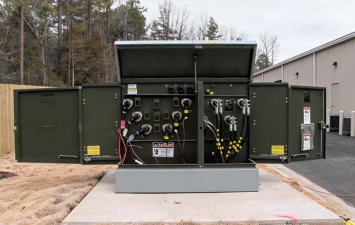
A common late change is cable direction. High-voltage cable bending radius, termination height, and phase sequence affect the tank opening and support steel. A high-current low-voltage busduct is sensitive to flange position, flexible connection, alignment, and mechanical support. Before the GA is frozen, the electrical, civil, and construction teams should complete a joint review. Every red-line comment should appear in the next controlled revision.
The transformer supplier normally provides rated currents, impedance, no-load current, reference information for magnetising inrush, losses, CT ratios and accuracy classes, temperature contacts, and mechanical protection contacts. The EPC protection engineer uses these inputs for differential, overcurrent, earth-fault, overload, and temperature settings. An OLTC package also requires tap-position indication, remote raise/lower commands, interlocks, limit positions, and the communication protocol.
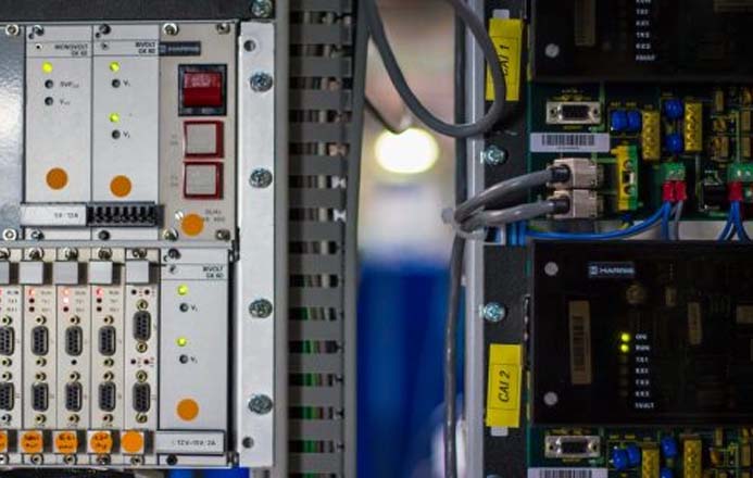
| Signal Type | Typical Points | Evidence Needed for Closure |
|---|---|---|
| Analogue | Oil and winding temperatures, current, tap position | Range, unit, 4–20 mA signal or communication map |
| Alarm | Low oil level, fan failure, high temperature | Contact state, terminal number, SCADA text |
| Trip | Buchholz relay, pressure relief, temperature high-high | Trip matrix, circuit voltage, fail-safe philosophy |
| Control | Fans, pumps, OLTC raise and lower | Local/remote authority, interlock, feedback |
| Communication | Modbus or IEC 61850 mapping | Protocol table, addresses, time sync, FAT script |
The final protection setting sheet is not a vendor-only deliverable. It should not be delegated to the control-panel supplier without system responsibility. The responsibility matrix must identify who supplies equipment data, who calculates the settings, who approves them, and who proves them by secondary injection on site. Our custom engineering solutions team can coordinate terminals, protocols, and package interfaces during the design stage.
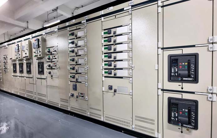
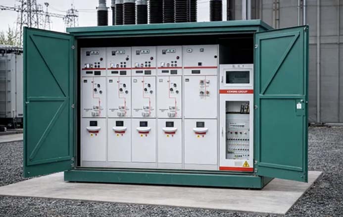
Power transformers, prefabricated substations, medium-voltage switchgear, low-voltage boards, RMUs, DC systems, and protection panels may be split across several purchase packages. The configuration schedule must reach a procurable level: equipment type, rating, quantity, incoming and outgoing arrangement, CT and VT data, relays, communication, auxiliary supplies, heaters, and spares. The phrase “complete package” creates different commercial interpretations unless these details are listed.
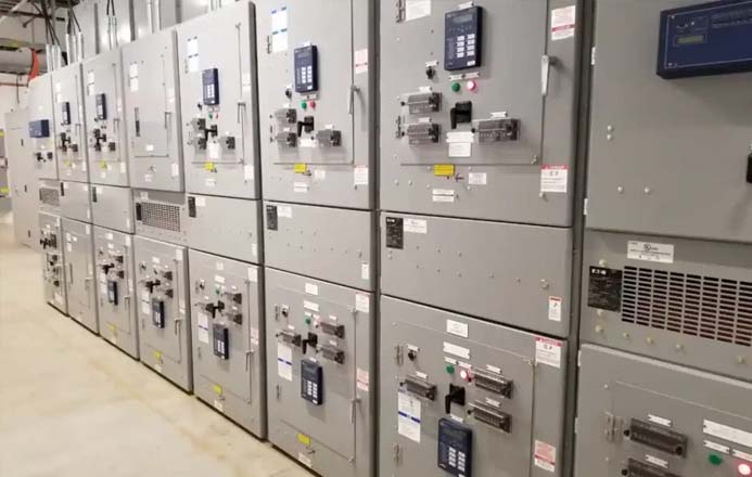
The scope diagram should identify both mechanical and electrical termination points. It should state who supplies cable terminations, busduct flexible links, earth bars, control cables, online monitoring, fire-system interfaces, and site oil treatment. Each item should appear consistently in the quotation, contract, drawings, and bill of materials. That prevents the familiar problem where an item is shown on a drawing but excluded from the contract.
An inspection and test plan can include document-review points, witness points, and hold points. For a transformer, useful stages include raw-material records, completed windings, active-part assembly, vacuum drying, oil filling, routine testing, accessory functions, and final visual inspection. The inspector should record measured values, photographs, instrument identification, and non-conformities rather than signing only an attendance sheet.
The FAT procedure should be approved before testing. It must identify standards, test connections, acceptance criteria, report format, and the response to an abnormal result. A package FAT should also prove secondary circuits, interlocks, communication, and point-to-point signals. For remote witness testing, camera coverage, live instrument views, and access to raw records should be arranged in advance.
The MDR normally includes approved drawings, calculations, type and routine test reports, material certificates, bills of materials, installation and operation manuals, spare-parts lists, packing lists, quality records, deviations, and closed non-conformance reports. Each document needs a number, revision, planned date, actual date, review code, and final status. “Approved with comments” should not automatically mean “released for manufacture”; the project must identify which comments can be closed in the next revision.
Shipment release should be linked to document readiness. Foundation drawings, lifting details, oil-treatment procedures, and installation manuals are required before the equipment reaches site. Final as-built drawings, test reports, and spare-parts records may follow contract milestones. Zisheng Electric’s technical support and after-sales service can assist installation, commissioning, and technical issue closure, while site safety control and work permits remain under the project organisation.
The weekly interface meeting should concentrate on open items: whether the input has been received, whether the technical conclusion appears in a controlled document, whether downstream documents have been updated, and whether the change affects cost or schedule. Closed items remain recorded and do not need repeated discussion. A revised requirement is reopened with a new owner and date.
Zisheng Electric supports EPC contractors, engineering companies, and project owners with oil-immersed transformers, dry-type transformers, compact substations, Pad Mounted Transformers, Pole Mounted Transformers, substations, and related distribution equipment. We can provide technical matching based on project capacity, voltage level, environmental conditions, and technical specifications, with an initial response to inquiries within 24 hours. Send the datasheet, single-line diagram, and MDR requirements so that the interface matrix, equipment configuration, FAT plan, and delivery documents can be reviewed from one baseline.

In EPC projects, transformer issues rarely appear during the quotation stage. They usually become visible later — during installation, inspection, or commissioning, when changes are costly and project schedules are already under pressure. A transf...
View details
Coordinate transformer fire protection for EPC projects: separation, oil containment, drainage, detection, suppression, control logic, FAT and site testing.
View details
Plan high-voltage switchgear commissioning with interface checks, interlock tests, protection verification, control-power proving and energization release evidence.
View details
A practical EPC transformer site acceptance test checklist covering delivery inspection, assembly, oil work, electrical tests, protection proving, energization and handover.
View details