 zishengelectric






Project Partners
Phone/WhatsApp: 8619131285373
Email: info@zishengtransformer.com
Factory Headquarters: No. 118, Jingyi Street, Economic Development Zone.
Search productSearch post
Project Partners
Phone/WhatsApp: 8619131285373
Email: info@zishengtransformer.com
Factory Headquarters: No. 118, Jingyi Street, Economic Development Zone.
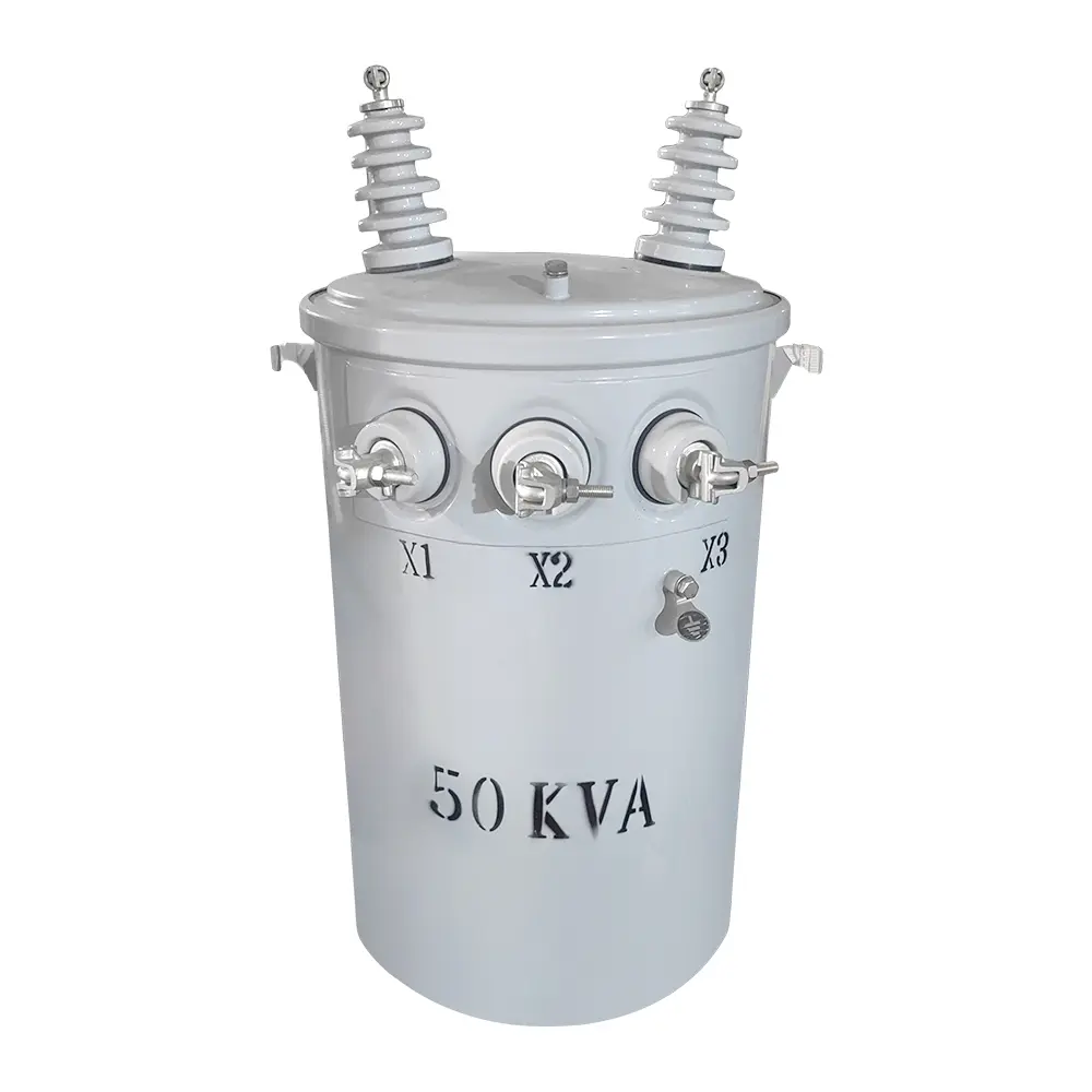
The 50kVA conventional single-phase pole-mounted transformer is designed to step medium-voltage distribution power down to a stable low-voltage supply. It is commonly installed on utility poles for residential communities, rural electrification, farms, small commercial facilities and municipal distribution networks.
Unlike a CSP transformer, the conventional type normally relies on externally installed primary fuses, surge arresters and secondary protection. Primary voltage, secondary voltage, winding material, insulating fluid, bushings and mounting accessories can be customized for different utility standards.
| Parameter | Standard Configuration / Options |
|---|---|
| Rated Capacity | 50kVA |
| Transformer Type | Conventional single-phase pole-mounted transformer |
| Phase | Single phase |
| Primary Voltage | 2.4kV–34.5kV or customized |
| Secondary Voltage | 120/240V, 240/480V, 277V or customized |
| Rated Frequency | 50Hz or 60Hz |
| Cooling Method | ONAN |
| Winding Material | Copper or aluminum |
| Core Material | Cold-rolled grain-oriented silicon steel |
| Insulating Fluid | Mineral oil or natural ester fluid |
| Tapping Range | Typically ±2 × 2.5% or customized |
| Temperature Rise | 55°C, 65°C or project-specific |
| Tank Construction | Sealed cylindrical steel tank |
| Primary Bushing | One- or two-bushing configuration |
| Secondary Bushings | Three- or four-bushing arrangement |
| Mounting | Single-pole mounting brackets |
| Installation | Outdoor |
| Standard Altitude | Up to 1,000m; high-altitude design available |
| Ambient Temperature | According to IEEE, CSA, IEC or project requirements |
| Applicable Standards | IEEE C57, ANSI, CSA, IEC 60076 or specified utility standard |
| Polarity | Additive or subtractive according to the approved design |
| Finish | Weather-resistant coating; custom colour available |
| Expected Service Life | Approximately 25–30 years with correct loading and maintenance |
Common primary and secondary voltage combinations include:
The primary voltage should be specified as both the system voltage and the actual phase-to-neutral voltage applied to the transformer.
| Voltage Side | Example Voltage | Approximate Rated Current |
|---|---|---|
| Primary | 7.2kV | 6.94A |
| Primary | 13.2kV | 3.79A |
| Primary | 14.4kV | 3.47A |
| Primary | 24.94kV | 2.00A |
| Secondary | 240V | 208.3A |
| Secondary | 480V | 104.2A |
Rated current values are calculated from the full 50kVA capacity and must be confirmed against the approved voltage configuration.
The cylindrical tank and integrated mounting brackets provide a compact installation footprint. The transformer is suitable for overhead distribution systems where ground space is limited.
The core uses grain-oriented electrical steel with optimized joints to reduce no-load loss, excitation current, operating noise and vibration.
Copper or aluminum conductors can be supplied. The winding structure is mechanically reinforced to withstand short-circuit forces, voltage fluctuations and normal transportation stresses.
The core and coil assembly is immersed in insulating fluid, which provides electrical insulation and transfers heat to the tank wall. ONAN cooling requires no external fans or pumps.
The sealed tank limits contact between the insulating fluid and outside air, helping reduce moisture ingress, oxidation and maintenance requirements.
The transformer can be supplied with:
| Feature | Conventional Type | CSP Type |
|---|---|---|
| Primary Fuse | Normally installed externally | Usually integrated |
| Surge Arrester | Normally installed externally | May be factory-mounted |
| Secondary Breaker | Not normally included | Commonly integrated |
| Protection Coordination | Designed by utility or project engineer | Partially integrated into transformer |
| Maintenance | Simple transformer construction | More integrated components |
| Application | Flexible utility protection schemes | Standardized distribution networks |
A typical 50kVA conventional pole-mounted transformer includes:
Available accessories include:
| Customizable Item | Available Options |
|---|---|
| Primary Voltage | 2.4kV–34.5kV |
| Secondary Voltage | 120/240V, 240/480V, 277V or customized |
| Frequency | 50Hz or 60Hz |
| Winding Material | Copper or aluminum |
| Primary Connection | Single-bushing or dual-bushing |
| Secondary Connection | Centre-tapped or project-specific |
| Tap Range | Standard or customized off-circuit taps |
| Insulating Fluid | Mineral oil or natural ester |
| Temperature Rise | 55°C or 65°C |
| Efficiency | Utility- or market-specific efficiency level |
| BIL | Selected according to the voltage class |
| Tank Material | Carbon steel or stainless steel |
| Paint Colour | Light grey, green or custom colour |
| Corrosion Protection | Standard, coastal or heavy-duty system |
| Mounting | Standard or customized pole brackets |
| Accessories | Arresters, fuse brackets, wildlife guards and terminal covers |
| Standards | IEEE/ANSI, CSA, IEC or customer specification |
Each transformer is tested before shipment. Routine tests can include:
When required, the following tests can be arranged:
The 50kVA conventional single-phase pole-mounted transformer is suitable for:
The transformer is protected for international transportation with:
Shipment can be arranged by sea, road, railway or multimodal transportation.
Please provide:
Final losses, impedance, BIL, dimensions, weight and accessory configuration are subject to the approved utility specification and manufacturing drawings.
Each 50kVA conventional single-phase pole-mounted transformer undergoes material inspection, manufacturing-process control and final electrical testing before shipment. Tests are performed according to IEEE C57, ANSI, CSA, IEC 60076 or the customer’s utility specification.
| Test Item | Inspection Purpose |
|---|---|
| Winding Resistance Measurement | Verifies winding continuity and connection quality |
| Voltage-Ratio Measurement | Confirms the designed voltage ratio at every tap position |
| Polarity Verification | Checks the relationship between primary and secondary terminals |
| No-Load Loss Test | Measures magnetic-core losses at rated voltage |
| No-Load Current Test | Evaluates excitation current and core condition |
| Load-Loss Test | Measures winding and stray losses |
| Impedance Measurement | Confirms impedance against the approved design |
| Insulation Resistance Test | Evaluates insulation between windings and the grounded tank |
| Applied Voltage Test | Verifies the main insulation strength |
| Induced Voltage Test | Checks inter-turn and inter-layer insulation |
| Insulating-Fluid Test | Confirms oil dielectric strength and condition |
| Tank Leakage Test | Checks welds, gaskets, bushings and fittings for leakage |
| Dimensional Inspection | Confirms overall dimensions and mounting arrangement |
| Accessory Inspection | Verifies terminals, brackets, grounding points and pressure device |
The following tests can be arranged when required:
Customer representatives or an authorized inspection company may witness the Factory Acceptance Test. The final documentation package can include approved drawings, nameplate details, test reports, calibration records, inspection photographs and packing records.
All acceptance criteria are confirmed according to the applicable standard and approved utility specification.
 50kVA Conventional Type Single Phase Pole Mounted Transformer