 zishengelectric



news
News Center
Providing high-quality power to the world
Search productSearch post
news
Providing high-quality power to the world
Zisheng Electric works with EPC teams that must coordinate transformers, switchgear, cables and the building that protects them. Substation cable penetration firestopping is a small interface on a drawing, yet it can delay energization when the opening, cable installation and approved seal do not match. An electrical contractor may leave spare capacity for future circuits; the civil contractor may close the wall; the firestop installer may arrive after access has disappeared. At handover, a photograph of red material around cables does not establish that the assembly matches an approved system.
This guide treats each penetration as an engineered interface. It explains what to freeze in design, what to check before cables are pulled, and what evidence to retain when the seal is installed. The project specification, applicable jurisdiction and approved firestop system control the final selection. A generic product name or an assumed fire rating cannot substitute for those documents.
The cable schedule identifies circuits, but it seldom tells the firestop designer everything about an opening. A useful register gives each penetration a unique location, wall or floor reference, drawing revision, construction type, intended cable or tray contents, opening dimensions and required performance. It also names the party responsible for cable supports on both sides. If the assembly is not fire resistance rated, record the actual project requirement rather than automatically applying a rated through-penetration detail.
At an EPC interface review, compare architectural fire compartment drawings with electrical cable routes and the civil opening schedule. The gap between these drawings is where late field changes begin. A tray may be rerouted to avoid a beam; an additional control cable may share a power opening; a spare sleeve may be kept open for future installation. Each change can alter whether the selected system still applies. The existing transformer fire protection interface review helps align this penetration register with containment, separation and fire system decisions elsewhere in the station.
Mark whether the opening passes through a fire rated wall, floor or enclosure, and identify the responsible design authority for that boundary. Confirm the required fire resistance and any smoke, water or movement performance from approved project documents. Firestop ratings belong to a tested assembly, not to a cartridge of material in isolation. UL Solutions distinguishes a listed firestop system from generic fireblocking and explains that testing such as UL 1479 or ASTM E814 concerns the complete penetration assembly; applicability still depends on the local code and project approval.
An installer also needs the actual substrate and thickness. A listed detail for one wall build-up may not transfer to a different blockwork, concrete or board construction. The UL Solutions firestopping design guide calls out opening size, service type, substrate, movement and required performance as inputs to system choice.
It is tempting to specify “approved firestop” in a general note and let the installer decide on site. That leaves the hardest questions unanswered: whether a tray can pass through the listed opening, how many cables it may contain, and how the cables are supported. Obtain the current system listing or approved project detail for the specific wall or floor, cable group and opening geometry. Compare every field condition with that detail before ordering materials.
| Decision input | Evidence to obtain | Why it changes the decision |
|---|---|---|
| Barrier and required performance | Approved fire compartment plan, construction detail and project specification | The assembly type and required rating determine which system listings can be considered. |
| Opening and sleeve geometry | As-built dimensions, edge condition, sleeve type and wall or slab thickness | A detail can exclude oversize openings, different sleeves or unsuitable substrates. |
| Cables, conduits and tray | Cable schedule, outside diameters, tray type, fill and planned spare routes | The penetrants and fill may determine the allowable tested configuration. |
| Movement and supports | Tray support layout, expansion or vibration assessment and approved detail | The seal should not be assumed to carry cable weight or accommodate unlisted movement. |
| Moisture and exposure | Room classification, drainage path and specified water or smoke criteria | Fire resistance alone does not establish water tightness or smoke control. |
| Inspection access | Sequence plan and hold-point photographs | Both faces, backing and hidden layers may become inaccessible after closure. |
Use the table to close interfaces, not as a substitute for a listing. The UL Firestop and Joint Application Guide describes systems as combinations of components and warns against unpermitted substitutions. It also identifies different listing categories for electrical cables, cable trays and other penetrants. Record the exact approved system and its revision in the penetration register.
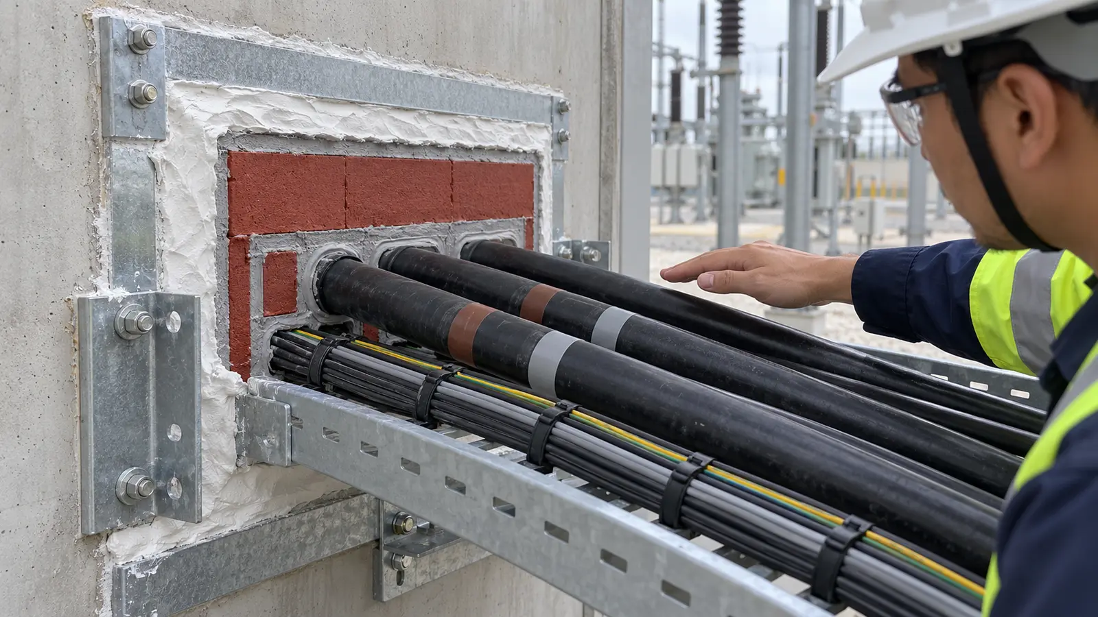
Penetrations connect the building with equipment layout. An opening close to a switchgear rear panel can obstruct maintenance space; a cable rise beneath a transformer terminal box can force a tight bend or make support installation difficult. Review wall and floor openings while the transformer and GIS interface is still being coordinated. Confirm the actual equipment outline, access doors, lifting path and cable termination envelope. The penetration drawing should show enough space for the approved seal and for the installer to reach it.
Cable trays must be supported independently according to the selected system detail and the electrical support design. Do not expect the firestop material to restrain a loaded tray. Large power cables have minimum bending radii and pulling limitations set by their manufacturer; use the project cable data rather than a universal number. Where a cable changes direction immediately after passing a wall, check that the route permits both the bend and the seal installation without crushing or crowding the cables.
Separate engineering decisions that are often collapsed into one detail. A wall opening may need fire performance, a weather exposed opening may need moisture control, and an electrical room may have environmental sealing requirements. These functions can interact, but their acceptance criteria are not identical. If water ingress, smoke leakage or movement is specified, select an assembly documented for that performance and record the project authority that accepts it.
Before cable pulling, confirm the opening ID, dimensions, substrate, rough edge condition and any sleeve or framing. Record deviations while the opening is still visible. After pulling, compare the installed cable types, number and tray position with the approved detail. The installer should then prepare the substrate and install each component in the specified order. Backing, depth, annular space and finish matter only to the extent prescribed by the actual system, so the field checklist should cite that system rather than impose generic dimensions.
Photograph each side at a useful scale, including the opening ID and enough surrounding structure to locate it. Where the assembly includes concealed backing or multiple layers, take an intermediate photograph before the final face hides them. A finished surface photograph alone cannot show what is behind it. A commissioning inspector may also need to confirm that adjacent cable terminations and supports remain accessible. If a defect is found, define a repair route through the approved design authority rather than adding more material without a revised detail.
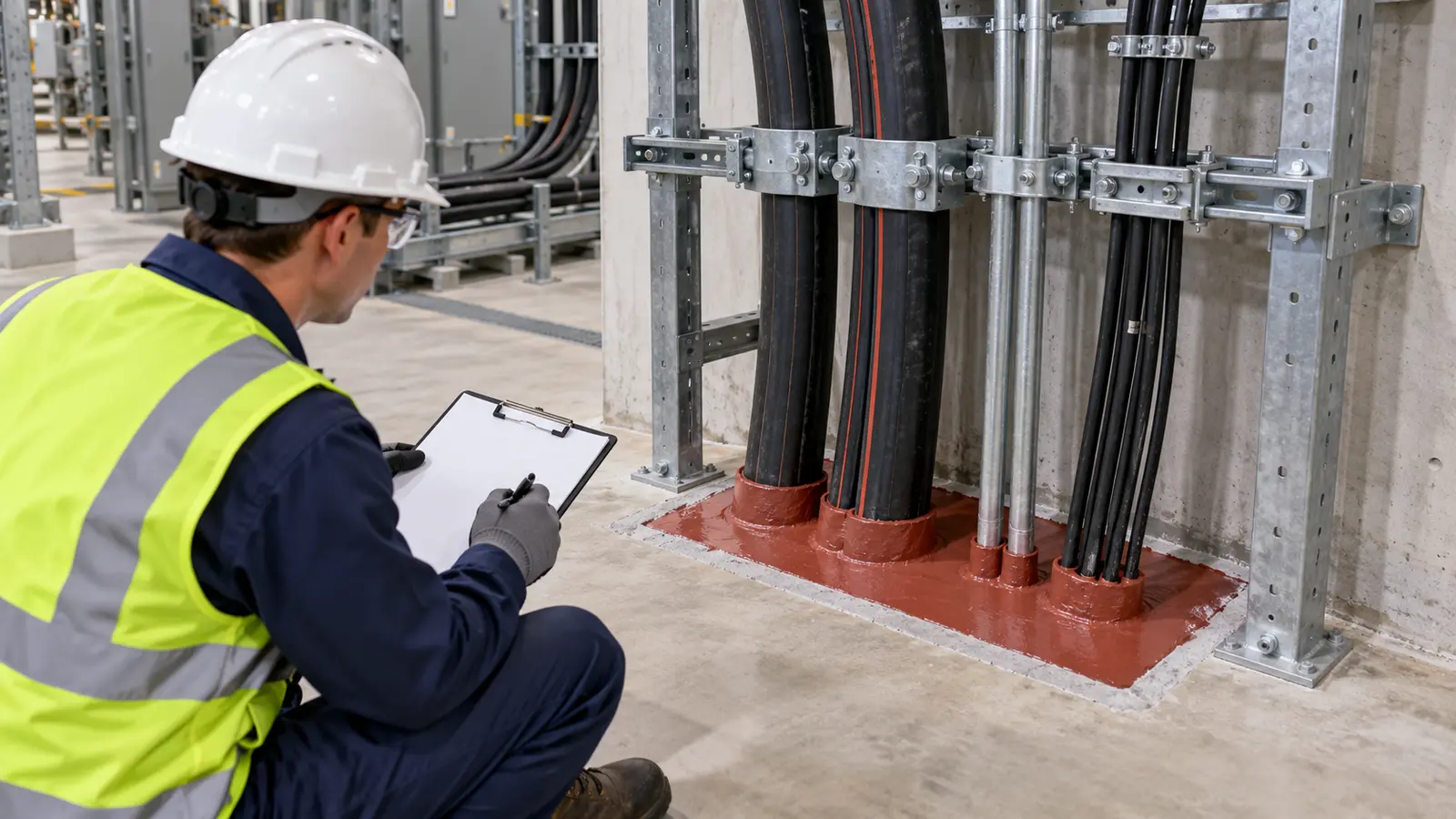
An inspection record should connect a physical opening to a drawing, an approved system and a date. Include the opening ID; room and barrier reference; approved system number and revision; product batch or delivery evidence where the project requires it; installer and inspection signatures; photographs before and after closure; and any nonconformance and repair approval. The acceptance form should distinguish “installed,” “inspected” and “released.” An unresolved deviation must remain visible in the punch list, even if the surface looks finished.
UL’s application guidance explains why these details matter: systems are installed as tested and the specified components are not interchangeable merely because they look similar. It also says that where a listing calls for independent support, the firestop is not the support. Match the inspection checklist to the chosen detail and the project specification, not to a generic photograph.
EPC schedules change. A new metering cable or an additional communication circuit may be requested after the original opening is sealed. Treat reopening as a design change. Record the removed material, new penetrant, remaining clearance and reinstated system, then reinspect the finished work. If future capacity is expected, decide at design stage whether an approved modular or re-enterable system is suitable. Do not assume that every firestop can be opened, refilled and resealed with the same rating.
Spare conduits and sleeves deserve the same control. An empty sleeve through a rated barrier is not automatically compliant because it has no cable. Its treatment depends on the approved detail and project fire strategy. Identify spares in the register, label them in the field and put any future installation instruction into the O&M package. This reduces the chance that a later contractor cuts an undocumented hole beside an existing seal.
Change control also reaches the electrical design. Added cables can alter tray fill and route congestion. If power circuits or protection wiring are changed, revisit the related substation arc flash study inputs and protection documentation where applicable. A penetration record does not replace those studies, but it points the team to the affected cable routes.
At mechanical completion, hand over a marked-up penetration register, approved drawings and system documents, material records, installation photos, inspection forms and outstanding punch items. For each barrier, the owner should be able to answer three questions: what passed through it, what was installed around it, and who accepted the work. A digital index keyed by opening ID is more useful than an unlabelled folder of photographs. The operations team will later need this record when they add circuits or replace damaged cable.
Keep the final walkdown separate from the original installation check. Verify that later trades have not cut new openings, damaged seals, removed supports or obscured labels. Inspect interfaces near doors, ventilation penetrations and cable trenches that share the same barrier. If water is present near a floor penetration, address the drainage or environmental issue through its own engineering review as well as checking the seal. Firestop material should never be used as an improvised remedy for an unresolved drainage design.
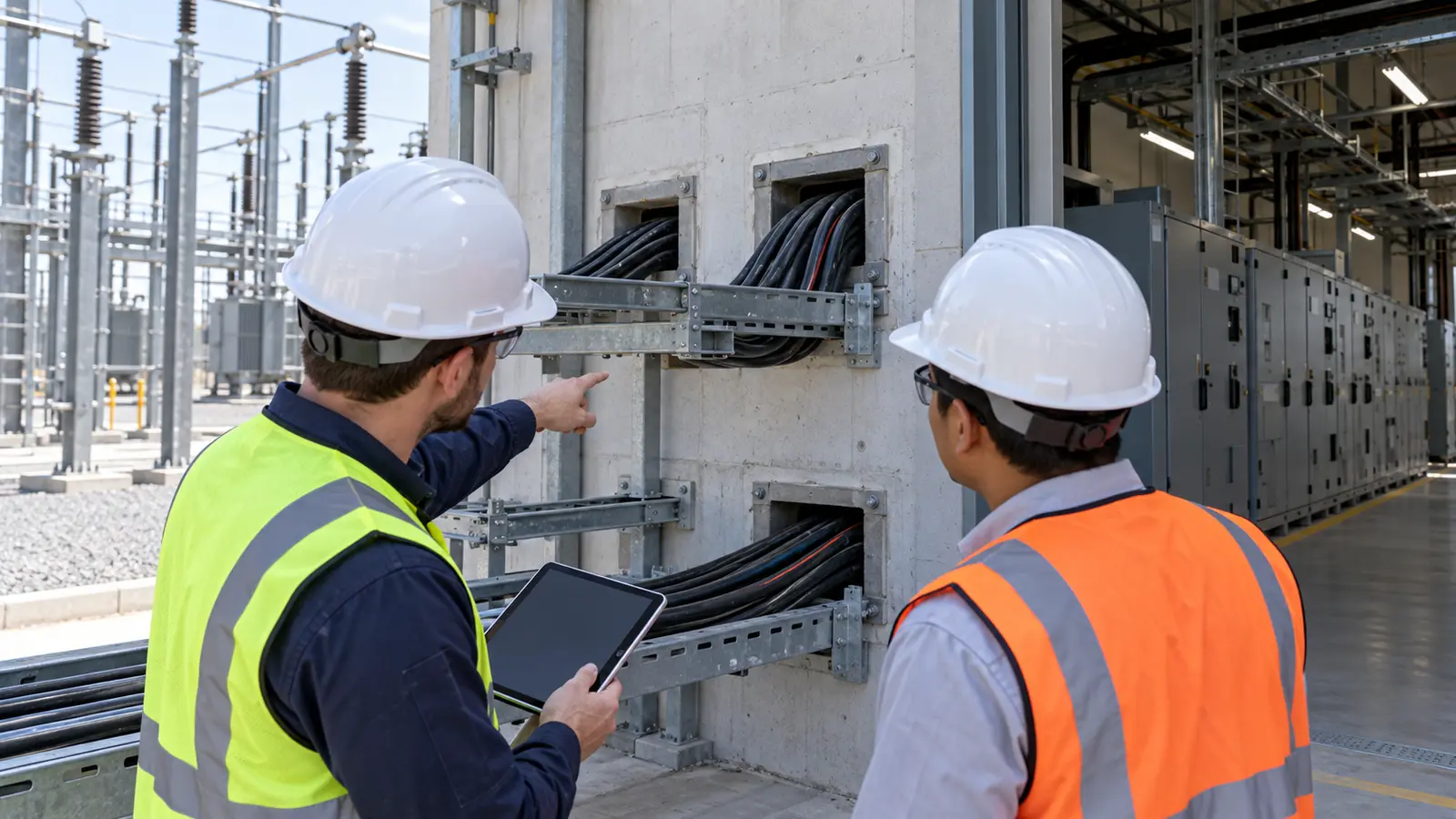
For procurement, ask bidders to identify their proposed listed system, supported barrier and penetrant configuration, installation competence, inspection hold points and documentation deliverables. Avoid accepting a material-only quote when the project needs a complete installed and traceable assembly. A clear scope also prevents the electrical, civil and firestop subcontractors from each assuming another party will prepare or repair the opening.
Zisheng Electric can review transformer and substation equipment arrangements while the EPC team closes the cable interface. Layouts for medium-voltage switchgear, low-voltage switchgear and power transformers help locate cable entries, service access and nearby barriers. Firestop design and approval remain the responsibility of the project’s competent design and fire protection parties; equipment dimensions and terminal positions are inputs they need early.
For a practical substation cable penetration firestopping review, send Zisheng Electric the equipment drawings, data sheets, load list, technical specification, single-line diagram, grid parameters, environmental conditions and installation site conditions. Add the cable schedule, barrier plan, opening register and any approved fire strategy or system detail. With those interfaces visible, our team can identify equipment and access conflicts before the opening is built. Our engineering team will review the requirements and respond to project inquiries within 24 hours.
Plan a substation water ingress walkdown for EPC handover: inspect roof drainage, thresholds, cable penetrations, trenches and electrical enclosures; assign repairs and release evidence.
View details
Coordinate the transformer GIS interface across terminal geometry, cable route, insulation, protection, grounding, installation and integrated testing. An EPC decision matrix identifies drawing owners, freeze dates and handover evidence.
View details
Plan substation as-built drawing reconciliation with field evidence, interface checks, discrepancy ownership and controlled EPC handover records.
View details
Plan substation arc flash study inputs for EPC projects: source fault data, transformer impedance, switchgear geometry, protection settings and as-left handover.
View details