 zishengelectric



news
News Center
Providing high-quality power to the world
Search productSearch post
news
Providing high-quality power to the world
Substation cable trench cover acceptance is a civil, electrical and maintenance interface, not simply a count of delivered panels. Zisheng Electric recommends resolving the cover system alongside equipment layouts and cable access requirements. A panel can look complete while its supporting frame, bearing surface or intended traffic duty remains unverified. Those omissions become expensive when the trench is already carrying cables and the surrounding area is in service.
For an EPC team, the practical objective is to establish that the installed cover-and-support arrangement matches its approved duty and can be maintained without disrupting essential access. This guide explains the records and observations that support that decision. It does not provide structural design values, authorize vehicle crossings or replace the selected manufacturer’s installation instructions.
Divide the trench route into identifiable sections. Some sections may be pedestrian areas; others may cross a vehicle route or sit near a transformer replacement path. Construction traffic can differ from normal operating traffic. A route that usually sees only pedestrians may later receive a maintenance vehicle, lifting equipment or a stored component unless the restrictions are clear.
For each section, record the proposed loading cases, clear opening, support arrangement, panel orientation and environmental exposure. Let the civil designer determine the required structural basis with the cover supplier. A product class, nominal panel thickness or overall vehicle mass is not enough to establish the suitability of an actual crossing. Wheel positions, local loads and the load path into the surrounding structure matter.
Agree how construction loads will be controlled before permanent acceptance. Do not use an unapproved cover as a convenient bridge for delivery equipment. Where temporary protection or a separate crossing is needed, it requires its own engineered arrangement and release. The permanent cover inspection should also identify damage that may have occurred during construction use.
Record changes to the access plan. Moving a gate, revising a delivery route or changing the equipment replacement strategy can turn a pedestrian section into a traffic interface. The cover schedule must follow that change rather than retaining an obsolete duty description.
The panel transfers load through its bearings, frame and supporting civil structure. Review those elements together. Check the approved detail for support continuity, frame joints, anchors where applicable and the dimensions of the supporting rebate or beam. A strong panel cannot compensate for a frame that lacks its required support.
Request the supplier’s applicable technical evidence for the precise system offered. Identify the tested or assessed configuration and any limitations on span, supports and installation. Do not present a test on a different panel or frame as evidence for the installed arrangement without the designer’s documented justification. Product literature is useful for selecting questions, but the acceptance basis belongs in the approved project documents.
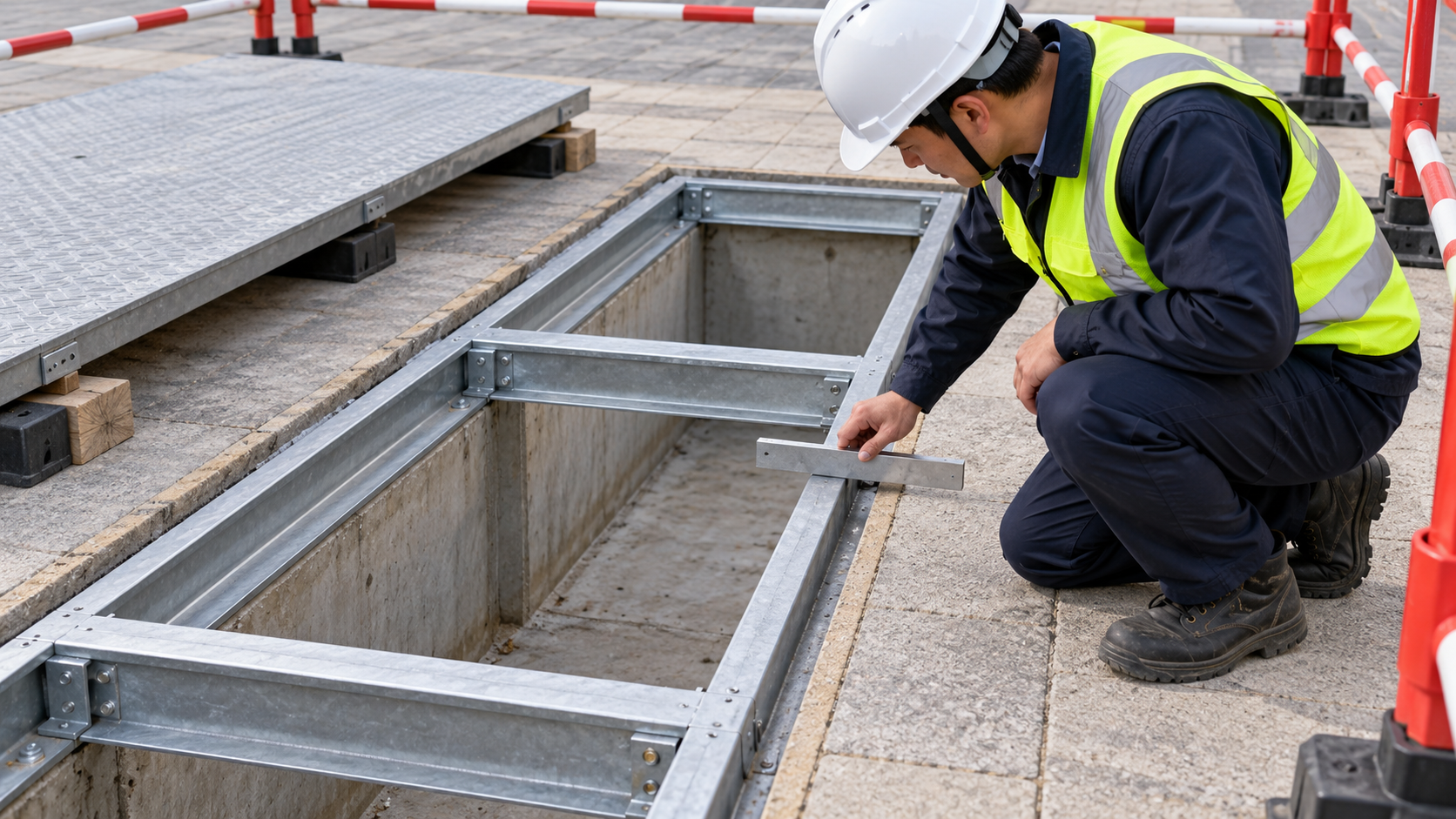
Uneven seating can leave a panel rocking or carrying load differently from the intended detail. Debris, damaged edges and local high points deserve attention before acceptance. The permitted tolerances and repair method should come from the approved system, not an improvised rule written during the walkdown. If the supporting concrete is defective, identify the responsible civil reviewer instead of concealing the problem beneath the cover.
As one manufacturer-specific example, Fibrelite’s GRP frame fitting instructions recommend positioning covers in the frame and checking flatness and sizing before concreting. Those instructions also address joints in long frame runs. This is not a universal instruction for every cover material; it illustrates why the selected assembly’s sequence and details must be available before installation.
Use the trench route identifier to connect drawings, material records and field observations. A schedule with only a total number of covers cannot show whether the correct panel is installed at a crossing or whether a special end piece has been substituted. Include corners, changes in width, access openings and sections beside equipment foundations.
| Review item | Required project input | Useful acceptance evidence | Decision if unresolved |
|---|---|---|---|
| Service duty | Pedestrian, vehicle and maintenance loading cases | Approved section duty and applicable supplier evidence | Restrict access pending designer review |
| Support arrangement | Opening, frame, bearing and civil support detail | Dimensional inspection and concealed-work records | Hold the affected section before covering |
| Panel identity and condition | Approved type, orientation and location schedule | Receiving record and installed location check | Quarantine unmatched or damaged components |
| Fit and surface level | Supplier tolerances and finished levels | Seating, joint and level observations | Obtain an approved correction and reinspect |
| Maintenance opening | Handling method, panel mass and available workspace | Controlled access demonstration and tool inventory | Revise the access arrangement before handover |
| Water and electrical interfaces | Drainage, sealing and earthing design where applicable | Coordinated drawings and installation checks | Return the interface to its responsible designer |
The table is a review framework, not a substitute for specified limits. Add document numbers, revisions, inspection responsibility and the final disposition of each finding. A signed checklist should show what was checked and against which requirement, rather than simply state “acceptable.”
At receipt, compare delivered components with the approved schedule and packing list. Check identification, dimensions where required, edges, surfaces and lifting features. Record visible damage before components are distributed around the site. A delivery shortage should not be resolved by moving a panel from a section with a different duty or support arrangement.

Follow the supplier’s storage and handling instructions for the actual material. Protect finished bearing surfaces and prevent site debris from becoming trapped between stacked components. Keep special panels and frames identifiable. If a panel is damaged, obtain an approved disposition; surface appearance alone cannot establish whether a structural repair is acceptable.
Ask early about replacement availability. A nonstandard panel may have a different lead time from a standard size, and replacement may require the original frame detail. Retain the supplier’s drawing reference and material identification in the asset records so that future maintenance does not depend on estimating dimensions from the opening.
A close-fitting cover should not automatically be described as watertight. Review the intended water-management strategy, including surface falls, frame details, drainage paths and any specified seals. Keep this work connected to the substation water ingress walkdown. Acceptance of the cover surface does not establish that the trench drainage system is complete.
The underground service coordination review addresses route clashes and concealed services. Cover acceptance starts where that layout work meets the finished access surface. Check that revised drains, cable supports or earthing connections have not reduced the space needed to remove a panel or interfered with its supporting frame.
At transformer and switchgear interfaces, compare the removable area with the actual cable approach and future work envelope. Panel removal should not require disturbing cable terminations or equipment supports. Conversely, an access opening should not leave an unreviewed interruption in the cover support. Resolve the geometry in the coordinated drawing before crews are asked to fit it on site.
For projects using 35 kV–46 kV power transformers or 110 kV–115 kV power transformers, equipment arrangement drawings should inform nearby trench access and replacement routes. These product ranges do not prescribe a trench cover rating. The civil loading and access design must be established for the actual project configuration.
Where metallic components require bonding, follow the approved earthing design and maintain the specified continuity across removable interfaces. Do not assume that an incidental mechanical contact is the intended bond. Equally, do not add unreviewed bonding arrangements to nonmetallic systems. The electrical designer should define the requirement and its inspection method.
A maintenance review should confirm that authorized personnel have the appropriate lifting tools, sufficient working space and a method for protecting the open trench. Consider panel mass, grip or lifting features, storage space for removed panels and the route by which tools reach the work area. A panel may be removable in theory but awkward beside a wall, fence or equipment door.
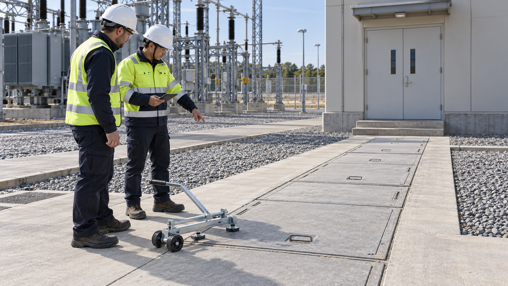
Plan any demonstration through the site’s authorized safe work system. Opening a trench can introduce fall, handling and electrical hazards even when the cover itself is satisfactory. The review should not become an improvised test in which a vehicle is driven over an unaccepted section. Structural testing, if required by the project, needs an approved method and competent oversight.
Check whether adjacent doors can open, emergency routes remain available and removed panels can be placed without loading cables or blocking access. For a long run, identify which panels are normally removed for a given maintenance task. This can reduce unnecessary handling while preserving the access needed for inspection and future cable work.
Classify findings clearly. A missing identification record, a damaged lifting feature, a rocking panel and an unverified traffic duty are different problems. Assign a responsible party, required correction and reinspection evidence to each. Avoid closing a structural or access issue with a photograph that only shows the panel has been put back.
Consider an illustrative late change: a cable route is widened beside a transformer bay after the cover order is placed. The original panel still reaches both sides, but the clear span and bearing conditions have changed. The correct response is a designer and supplier review of the revised assembly. It is not acceptance based on the fact that the panel physically fits over the opening.
Keep restrictions visible until the relevant section is released. If construction needs access before all evidence is complete, define the permitted use and its controls through the project process. Temporary use does not erase the outstanding acceptance condition. Update the section schedule after an approved change so that operations receives the installed basis rather than the original procurement assumption.
The final package should connect the route plan, section duties, approved panel and frame details, supplier instructions, receipt inspections, concealed-work evidence, installed checks and closed findings. Include replacement references, handling tools and operating restrictions. The owner should be able to identify a particular panel and understand its support and service conditions without reconstructing the construction history.
For a project enquiry, send Zisheng Electric the substation layout, transformer drawings, single-line diagram, cable route information, equipment access requirements, load list and environmental conditions. Include vehicle and maintenance loading proposals for review by the responsible civil designer. This allows transformer and substation interfaces to be coordinated before procurement and installation decisions become difficult to change.
Substation cable trench cover acceptance is complete only when the physical arrangement and its evidence agree. Zisheng Electric can support the equipment-side coordination while the appointed designers and suppliers confirm the cover system’s project-specific requirements. Our engineering team will review the requirements and respond to project inquiries within 24 hours.
Build substation cable cleat acceptance evidence: connect fault-study inputs, product qualification, support details, spacing checks and EPC handover records.
View details
Review transformer sound level FAT reports: align acoustic metrics, cooling cases, measurement evidence and acceptance decisions before EPC release.
View details
Plan transformer coating inspection for EPC projects: review paint records, thickness evidence, transport damage, compatible repairs and release boundaries.
View details
Review transformer kiosk condensation through heater supply, humidity controls, cable gland sealing, outage conditions and traceable EPC acceptance checks.
View details