 zishengelectric



news
News Center
Providing high-quality power to the world
Search productSearch post
news
Providing high-quality power to the world
Substation DC earth fault location should give the operating team a usable feeder identity, not just another common alarm. Zisheng Electric helps EPC teams define that outcome before auxiliary-power panels, protection cabinets and station-control interfaces are finalized. A successful acceptance review connects the monitoring function to the actual circuit arrangement, the alarm destination and the records the owner will use after handover.
This guide addresses an unearthed DC auxiliary system where insulation monitoring and fault location are part of the approved design. It does not assume that every substation uses that arrangement. The project must first confirm its DC system topology, nominal voltage, earthing philosophy, connected equipment and owner requirements. A grounded system or a different monitoring architecture requires its own assessment.
An insulation alarm and a located feeder are different deliverables. The first tells the operator that the monitored system has an insulation condition requiring attention. The second narrows the investigation to a defined circuit or zone. The purchase specification should say whether the project requires system-level detection only, automatic feeder location, portable investigation facilities, or a coordinated combination.
If the contract simply asks for an earth-fault alarm, a supplier may provide a functioning common indication without individual feeder identification. That is not necessarily a defective product; it may be an incomplete project requirement. Resolve the distinction before panel construction, when sensor space, cable routing and spare channels can still be coordinated efficiently.
IEC 61557-9:2023 covers equipment for insulation fault location in unearthed IT systems, including DC systems within its stated voltage scope. It is a relevant equipment reference where that scope matches the project. It does not, by itself, define the owner’s feeder naming, station alarm messages or the complete site acceptance procedure.
For every indication, ask what the operator is expected to do next. A system insulation warning may initiate investigation. A located feeder should identify a drawing reference and an equipment destination. A monitor malfunction should lead to a maintenance response distinct from an electrical insulation alarm. The alarm philosophy should explain those differences in ordinary operating language.
Do not promise that a location indication identifies the exact damaged terminal or cable section. Its resolution follows the installed monitoring zones and the validated system capability. A sensor serving several outgoing circuits can identify that group without distinguishing every downstream branch. Describe the actual boundary rather than overstating the diagnostic precision.
Start with the approved DC single-line diagram and a feeder schedule. Identify batteries, chargers, distribution boards, bus sections, couplers and connected control or protection equipment. Record which sections can be operated independently and which can be interconnected. Mark the monitoring boundary for each allowed configuration.
Our substation auxiliary power system guide discusses the wider supply arrangement. The earth-fault-location review should use the same controlled drawings and circuit identifiers. A separate spreadsheet with different names can become a source of commissioning errors even when every individual device is installed correctly.
For split and interconnected bus arrangements, obtain the monitoring supplier’s approved coordination method. Confirm how the equipment behaves when the electrical boundary changes and which monitoring or locating functions are active in each state. The EPC team should not infer compatibility merely because two panels use the same nominal DC voltage.
Account for connections that leave the main DC board through packaged equipment, interface cabinets or future extensions. Clarify whether spare feeders are fitted with monitoring hardware, reserved channels only, or no location provision. Distinguish an installed spare from a future allowance in the bill of materials.
Also identify temporary commissioning supplies and test connections in the method statement. Their presence can change the arrangement being demonstrated. A test performed with a temporary configuration should not be recorded as proof of a different permanent configuration without an explicit engineering explanation.

The location system needs a reliable relationship between the physical circuit and the displayed identity. Prepare a schedule that connects feeder designation, cable identifier, sensor or measuring-channel reference, panel position, destination equipment and alarm text. Include the relevant drawing revision and the responsible interface owner.
The schedule is an engineering control, not simply a documentation exercise. It allows the inspector to compare a cable route with a channel assignment and lets the commissioning team select a test case without guessing. It also gives maintenance personnel a route from an alarm message to the correct drawing and cabinet.
| Interface item | Required project decision | Acceptance evidence | Consequence if unclear |
|---|---|---|---|
| Monitoring boundary | Which DC section and operating states are covered? | Approved single-line diagram and configuration matrix | An alarm may be attributed to the wrong electrical zone |
| Feeder identity | What physical circuit does each channel represent? | Signed feeder-to-channel schedule and wiring inspection record | Investigation may start at the wrong equipment |
| Detection and location | What constitutes a system alarm and a valid location result? | Supplier-supported settings and agreed functional checks | A common alarm may be mistaken for feeder-level proof |
| Remote indication | Which message, quality and reset state reach station control? | End-to-end alarm record with timestamps | Local success may conceal a remote interface failure |
| Restoration | How is the normal configuration confirmed after testing? | Reinstatement checklist and final healthy-state record | Temporary test arrangements may remain undocumented |
Review the schedule with the DC panel supplier, protection-panel supplier, station-control integrator and site commissioning lead. An EPC interface is closed only when both ends agree. A channel name accepted by one supplier but absent from the station database remains an open item.

Use the selected manufacturer’s connection instructions to review sensor type, conductor routing, channel assignment and installation constraints. The Bender EDS440/EDS441 manual, for example, treats connection arrangements, commissioning requirements and system limitations as equipment-specific subjects. That is why a generic sketch cannot replace the approved instructions for the equipment actually supplied.
Ask the panel builder to provide an inspection view that makes channel identification possible without disturbing finished wiring. Labels should remain visible after covers, cable supports and adjacent equipment are fitted. Photographs can supplement the record, but they should identify the panel, circuit and drawing revision rather than show an anonymous cabinet interior.
Obtain supplier confirmation of the applicable system parameters and connected-load constraints. Where system capacitance, power electronics or network configuration affect the location function, put the accepted conditions into the design review. Do not copy a universal alarm resistance, locating current or response time from another project.
Separate guaranteed equipment capability from site-dependent performance. A bidder should identify the information needed to confirm suitability and the assumptions used in its offer. If an input remains unavailable, retain it as an open interface item with an owner and closure date; do not turn an assumption into a signed acceptance criterion.
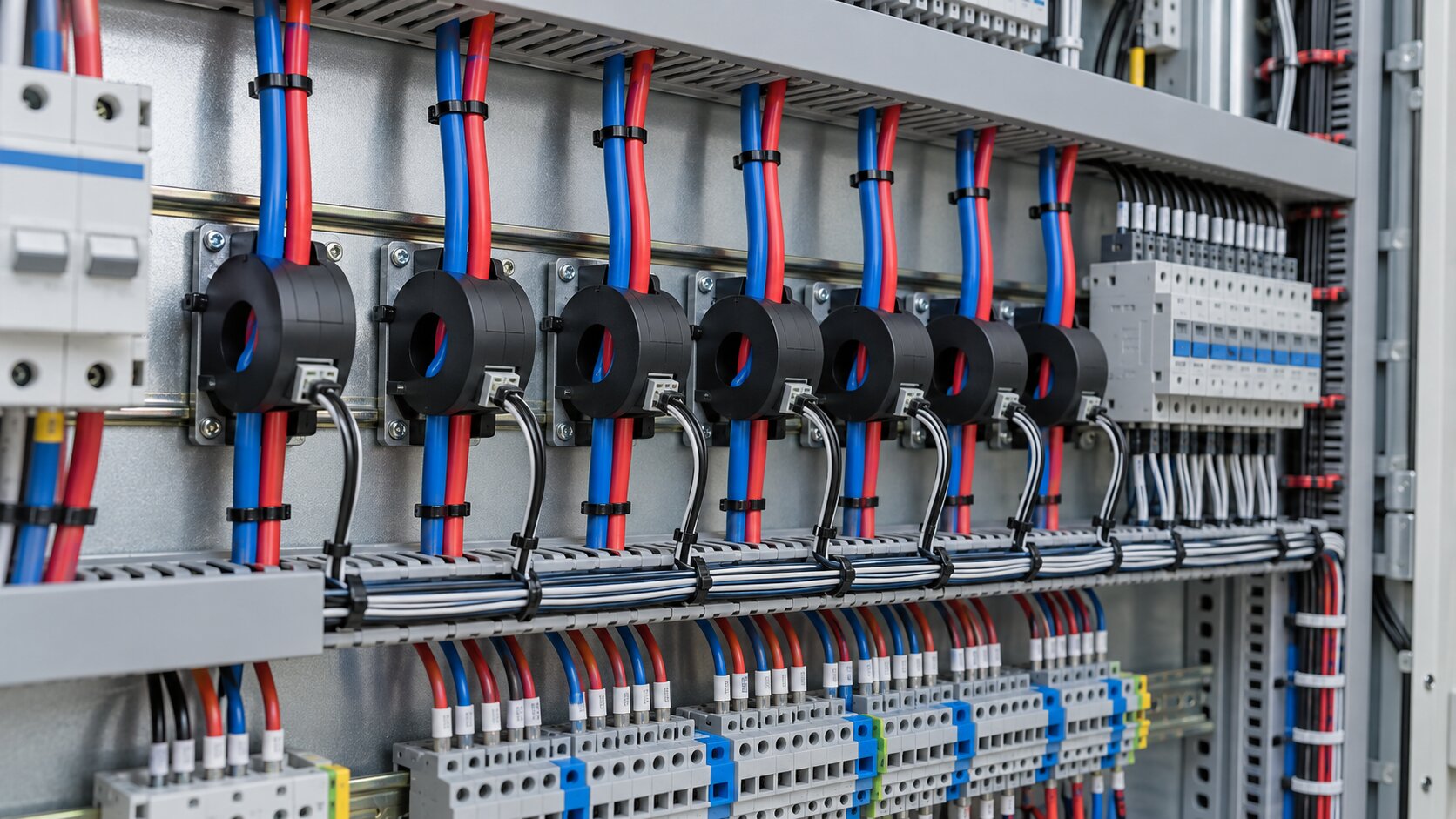
The inspection and test plan should map each required function to a method, an expected result and a record. Include representative feeder identification, local indication, remote alarm transmission, device-health indication and restoration. Select the coverage with the owner and suppliers, taking account of the installed architecture and project requirements.
A local display check does not prove the station-control mapping. Likewise, an injected signal at the control-system input does not prove the complete path from the field monitoring equipment. Use the test record to show which part of the chain was exercised and which parts were simulated or excluded.
For each accepted result, record the equipment identifier, configuration, settings revision, test method reference, observed indication and responsible witnesses. An unexplained tick in a spreadsheet is difficult to use when the owner later asks whether a particular feeder was actually checked.
Functional testing must follow an approved procedure prepared by qualified personnel with the equipment suppliers. The procedure should address isolation, authorization, connected protection and control loads, and restoration. This article does not prescribe a live fault-insertion technique or a resistor value for an energized station.
Avoid using routine feeder disconnection as an improvised diagnostic demonstration. The test team must understand the consequence for trip, close, interlock and auxiliary circuits before any circuit is disturbed. Choose the agreed verification method and identify any function that cannot be demonstrated under the current site conditions.
A concise alarm message should still distinguish the DC section and the located zone. Reconcile abbreviations between the panel display, station HMI, event list and maintenance documentation. If an operator has to interpret an undocumented numeric channel, the technical location function has not yet been translated into a useful operating interface.
Agree the treatment of active, cleared and acknowledged conditions. Confirm whether an alarm remains latched locally, whether remote acknowledgment changes any local state, and how equipment trouble is distinguished from an insulation condition. These behaviors depend on the selected devices and integration design, so record the agreed implementation rather than assuming a default.
Check timestamps and event ordering where they matter to the owner’s investigation process. State the source of time and any known limitations. A remote event log can support diagnosis only if the team understands what its recorded time represents and whether related devices share a consistent time basis.
Factory testing can verify panel wiring, labeling, configured channels and agreed interfaces under the factory arrangement. Site acceptance must address the installed circuits and the actual station integration. The handover file should distinguish those stages so that a factory result is not treated as proof of field wiring that did not yet exist.
Coordinate the relevant checks with the high-voltage switchgear commissioning plan. DC auxiliary functions cross equipment-package boundaries, and testing one cabinet in isolation may leave the final control path unresolved. Plan access and witness points before the commissioning sequence becomes constrained by energization milestones.
When a late feeder change occurs, update the channel schedule, labels, alarm database and test scope together. Repeating a test with an obsolete name may confirm electrical operation while leaving the owner with misleading records. Keep a clear link between the change and the evidence that closes it.
Deliver the approved topology, feeder-to-channel schedule, final settings, software or configuration versions where relevant, test results and open-item disposition. Include the supplier’s operating instructions and the project-specific response route for alarms. Record the support contact and the information required to investigate a reported issue.
Spare-parts planning should identify compatible sensors, monitoring modules and any configuration or licensing dependency that affects replacement. Confirm how a replacement device will receive the approved settings and how the affected functions will be checked afterward. A spare unit on a shelf is less useful if its configuration responsibility is unresolved.
Provide a short operator demonstration using the approved training arrangement. Show how to move from an alarm identity to the circuit schedule and drawing, how to distinguish device trouble from a system condition, and how to escalate the finding. Training should follow the installed system rather than a generic vendor presentation alone.
Zisheng Electric can coordinate auxiliary interfaces with custom low-voltage switchgear and prefabricated substation packages. The required DC monitoring and fault-location scope must be specified separately; these product links do not imply that a particular monitoring system is included as standard.
For a substation DC earth fault location review, send the approved single-line diagram, DC feeder schedule, battery and charger data, protection and control load list, monitoring equipment data sheets, alarm philosophy, technical specifications and installation drawings. Include the utility interface requirements, environmental conditions and available access within the panels and electrical rooms. Our engineering team will review the requirements and respond to project inquiries within 24 hours.

Substation local/remote control acceptance for EPC teams: verify command authority, rejected requests, mode transfers and traceable handover evidence.
View details
Review the substation fence earthing interface before construction: coordinate gates, security devices, civil changes, inspection records and EPC handover.
View details
Plan a substation pre-energization readiness review covering punch lists, transformer checks, protection tests, station DC, switching and permit controls.
View details
Plan a controlled transformer oil filling procedure for EPC projects, covering vacuum, oil quality, circulation, sampling, leak checks and handover.
View details