 zishengelectric



news
News Center
Providing high-quality power to the world
Search productSearch post
news
Providing high-quality power to the world
Substation bolted connection records should let an EPC reviewer identify a joint, locate its assembly requirements and understand what was actually checked. Zisheng Electric works with project teams on transformer and distribution-equipment interfaces, where this traceability matters long after a cabinet cover has been fitted. A line of paint across a fastener is useful information, but it cannot explain which instruction governed the work or who accepted a later disturbance.
This guide concerns the documentation and acceptance of accessible, field-assembled electrical joints at transformer terminals, busbar transitions and associated substation equipment. It is not a universal tightening procedure. Qualified personnel must use the equipment manufacturer’s approved instructions and the site’s electrical safety system, including isolation and verification of a safe working condition before access. The engineering decision is whether the evidence supports release of the defined connection scope.

Begin with the assembly boundary. Which joints were completed at the factory? Which were separated for transport? Which will be made by the site contractor? A general note stating that all connections were checked can hide a missing shipping-split joint or imply that sealed factory assemblies were opened unnecessarily. Identify the field scope on the equipment drawing before preparing the record sheet.
Assign a stable reference to each connection group: equipment tag, compartment, phase or conductor identity, drawing reference and joint position. Where one group contains several fasteners, define how the record distinguishes them. The inspector should be able to find the physical joint without depending on the memory of the original installer.
Keep alignment and support acceptance connected to this record without treating them as the same inspection. A properly recorded tightening operation does not resolve a forced connection or an unsupported conductor. The transformer cable termination and busduct interface review addresses those geometry and responsibility questions. Close the relevant prerequisites before accepting the joint assembly.
Ask the supplier for the applicable drawing and installation instruction, including revision and connection detail. The technical package should identify the specified hardware arrangement, contact preparation, tightening requirements and any restrictions on reuse. Bolt diameter alone is an insufficient basis for selecting an electrical-joint torque.
Schneider Electric’s MotorSeT installation instructions illustrate why scope matters: their bus-connection guidance distinguishes hardware materials and explicitly excludes the disconnector contact mechanism from the bus torque table. This is a product-specific example, not a torque schedule for another manufacturer’s transformer or switchboard.
The EPC reviewer should therefore require an approved instruction reference beside each joint family. If a terminal supplier and equipment supplier provide conflicting requirements, raise a technical query before work proceeds. Selecting the higher value is not a defensible way to resolve the conflict. The answer must address the assembled interface and identify who accepts it.
A number without a unit is incomplete. Keep the original specified unit visible, and control any conversion used by the contractor. Record the relevant assembly conditions from the instruction, such as the required hardware and any specified surface treatment. Do not add a lubricant, substitute a washer or change a plated contact preparation because a generic workshop practice uses it.
Separate a tool setting from a measured result. A preset wrench may provide confirmation that a prescribed operation was completed; it does not necessarily generate a stored numerical result for every fastener. Describe the evidence honestly. A form should not contain an invented measured value merely because its designer provided a numeric column.
The following table is a proposed EPC review framework. It does not establish universal torque limits, sampling percentages or inspection frequencies. Those requirements belong to the approved equipment instructions and project inspection plan.
| Record element | Evidence to retain | Decision it supports | Reason to hold the scope |
|---|---|---|---|
| Joint identity | Equipment tag, compartment, conductor and drawing position | The record can be matched to the installed connection | A signature covers an unidentified group of joints |
| Assembly basis | Approved detail, instruction revision and hardware requirement | The correct method applies to this interface | Site hardware differs from the approved arrangement |
| Tightening evidence | Specified value and unit, method, operator and completion date | The required operation is documented | A generic torque table replaces the equipment instruction |
| Tool traceability | Tool identity, applicable range and valid calibration reference | The tool was suitable for the recorded work | The tool cannot be connected to its verification record |
| Inspection status | Required witness or inspection record and marked joint location | The agreed inspection stage is complete | Paint is the only available completion evidence |
| Disturbance history | Reason for reopening, affected joints and reacceptance reference | The current condition matches the accepted record | Later work invalidates the earlier acceptance |
| Closure condition | Resolved deviations and reinstatement of relevant barriers or covers | The connection package can enter its next approved stage | An unresolved defect is hidden by enclosure closure |
Keep the sheet usable at the work location. A compact joint map with a controlled record is often clearer than repeating long descriptions in every row. When several identical panels are installed, retain their separate equipment identities; one completed sample record must not silently become evidence for the whole lineup.
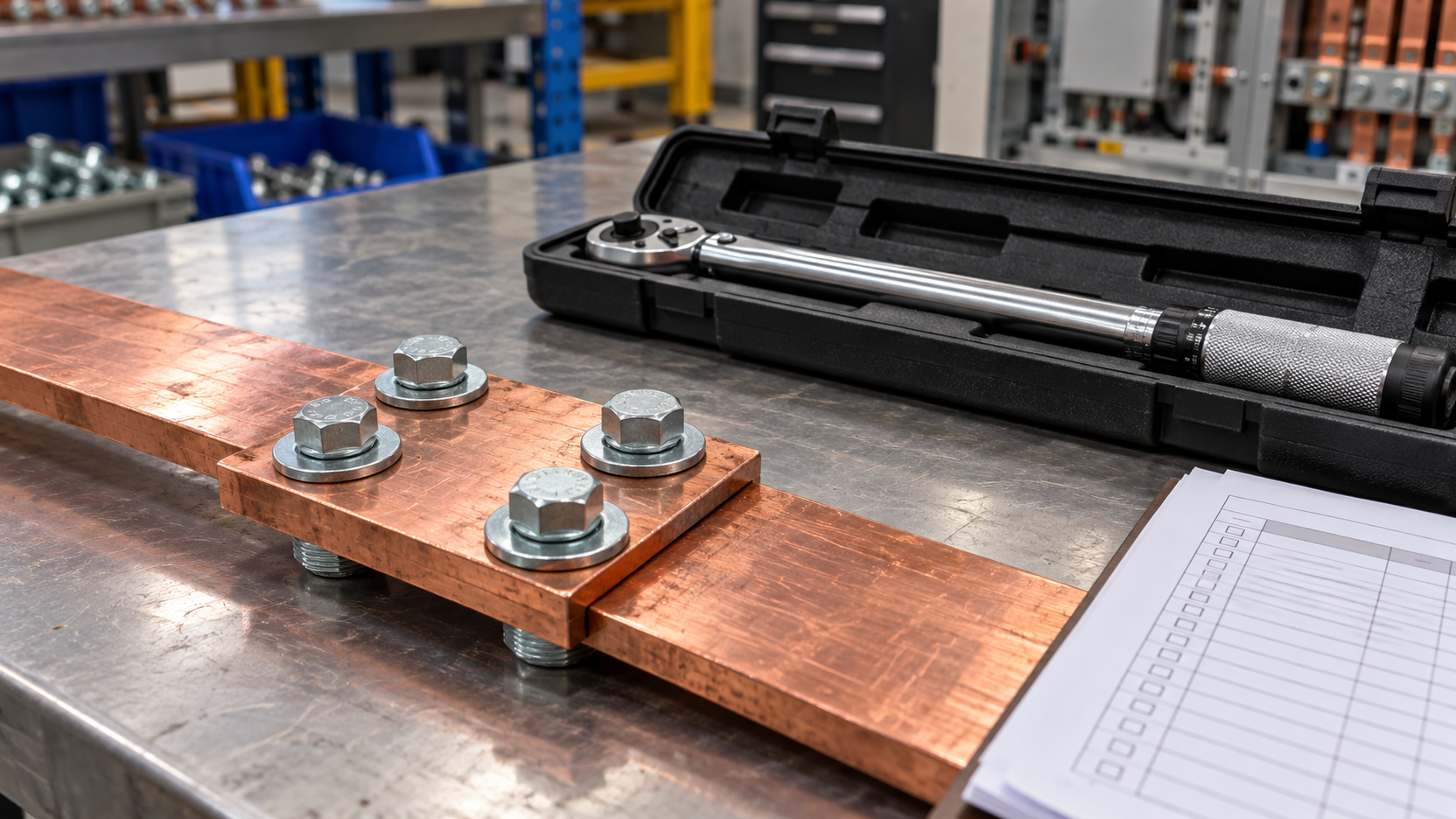
The tool record should identify the wrench used, the applicable operating range and the calibration or verification reference required by the project. Check that the identification on the tool matches the certificate. A certificate for a similar tool in the contractor’s store does not establish traceability for the tool used at the joint.
Norbar’s torque-control guidance explains that calibration integrity depends on use and environment and that the user must determine an appropriate interval. This supports a practical procurement question: how will the contractor demonstrate tool suitability throughout the work, including after a drop, suspected damage or other event requiring review?
Access deserves attention before the inspection date. Confirm that the approved tool and accessory arrangement can reach the connection in the installed configuration. If an extension, adapter or alternative tool is needed, obtain the appropriate method review. Do not assume that a familiar wrench setting remains suitable for every accessory configuration.
The quality plan should also describe what happens if a tool is later found outside its accepted condition. Preserve the work history needed to identify potentially affected connections. The responsible engineer can then define the extent of assessment; an unsupported assumption that all earlier joints remain acceptable makes the record system ineffective.
A witness mark can help an inspector recognize that a specified marking stage has been completed and can make subsequent movement or disturbance easier to notice. Its meaning depends on the approved procedure. Define when it is applied, which surfaces it references and how it relates to the signed record. Avoid assigning significance to a paint colour that the project has never defined.
For acceptance purposes, a photograph of paint does not independently establish the original torque, the tool identity or the condition of concealed contact surfaces. It should support a traceable record, not replace one. Likewise, an unbroken mark should not be treated as a measurement of present contact pressure or electrical performance.

Use a context photograph to show the equipment and joint location, then a detail where needed. Reference both from the record. A tightly cropped fastener photograph without equipment identity may be technically clear and administratively useless. Keep original observations available rather than relying only on an annotated presentation image.
Photographs also have limits. A visible bolt head cannot establish every concealed washer or the condition between mating surfaces. Decide before assembly which checks need to occur while those details remain accessible. If the inspection opportunity was missed, obtain an engineering disposition instead of asking the inspector to certify an unseen condition.
A connection accepted on Monday may be disturbed on Tuesday to correct cable routing or replace a component. The earlier record should remain available, but its status must reflect the changed condition. Identify the affected joints, the reason for disturbance and the instruction used for reassembly. Close the new inspection reference before treating the connection as accepted again.
A missing paint mark or missing document does not automatically justify turning every fastener again. Initial installation, investigation of a discrepancy and routine maintenance are different activities. As a product-specific example, Schneider Electric’s field testing and maintenance guide for molded-case circuit breakers advises against disturbing or re-torquing connections without evidence of overheating or looseness in the maintenance context described there. Apply the instructions for the actual equipment and activity.
If proposed corrective work changes hardware, a terminal arrangement or the approved assembly method, route it through the project’s transformer design change control process. A replacement fastener described as equivalent needs an accepted technical basis. The inspector should not have to approve a design substitution by signing an installation sheet.
Consider a hypothetical switchboard connection package with clear joint photographs and a signed installation sheet, but no reference to the applicable tightening instruction. The missing link is the assembly basis. First recover the controlled instruction that governed the work and establish whether it matches the installed hardware. If that cannot be demonstrated, request a documented engineering disposition. Do not reconstruct a plausible requirement from a generic internet table.
Now consider a package with complete records, but a later cable-routing change affected one terminal group. The task is narrower: identify the disturbed boundary and obtain its reacceptance evidence. Repeating the entire lineup inspection may add work without answering which records remain valid. Conversely, accepting the whole lineup because most records are complete leaves the changed group unresolved.
These are review examples, not reports of Zisheng Electric customer projects. Their purpose is to show how a useful record system directs attention to the actual evidence gap. Inspection effort should follow the affected scope and the approved quality requirements, with a named owner for each unresolved decision.

Organize the final package by equipment tag and connection group. Include the joint map, applicable instruction references, completion records, required inspection evidence, tool references, deviations and reopening history. State which factory assemblies were outside the field inspection scope. This prevents the owner from interpreting a site acceptance sheet as certification of work that the site contractor did not perform.
Before closing the package, verify that required insulating barriers, boots, covers and access provisions have been reinstated under the equipment procedure. Record outstanding restrictions explicitly. Completion of connection records is one input to commissioning readiness; it does not replace insulation checks, protection verification or the formal authorization to energize.
Procurement can make this easier by specifying the handover format before manufacture and installation begin. Ask for field-joint identification, relevant instructions and clear responsibility at the transformer-to-connected-equipment boundary. Late requests for evidence are harder to satisfy once access is closed and the original installation team has left.
For a package using a 35–46 kV power transformer or a 10 kV class oil-immersed distribution transformer, confirm the offered terminal arrangement and the supplier boundary before defining site records. Product voltage and capacity do not establish a universal connection method.
Send Zisheng Electric your drawings, data sheets, load list, technical specification, single-line diagram, grid parameters, environmental conditions and installation-site constraints. Include terminal details, connected-equipment information and the proposed inspection responsibilities so the substation bolted connection records can be planned around the actual interface. Our engineering team will review the requirements and respond to project inquiries within 24 hours.

Create a traceable transformer insulation-resistance baseline with a safe test boundary, environmental records, time-stamped readings and OEM-based interpretation.
View details
Build a substation system turnover package with clear boundaries, mechanical completion evidence, punch control and verified commissioning release records.
View details
Transformer nameplate verification for EPC handover: reconcile equipment identity, ratings, accessory records and approved corrections before release.
View details
Plan substation time synchronization acceptance with clock-source records, endpoint checks, event-time comparisons, loss-of-sync behavior and controlled EPC handover evidence.
View details