 zishengelectric



news
News Center
Providing high-quality power to the world
Search productSearch post
news
Providing high-quality power to the world
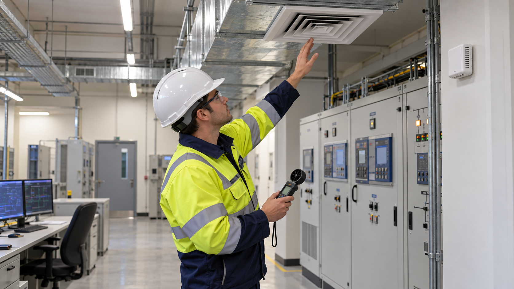
Zisheng Electric sees substation control room HVAC handover as part of the electrical commissioning boundary. The room may feel comfortable during a brief site visit while a relay rack has a recirculating hot pocket, a filter alarm has not been connected, or a cooling failure is missing from the operations response plan. EPC teams can prevent that gap by agreeing on equipment heat loads, design ambient conditions, airflow paths, alarm interfaces and witnessed evidence before the room becomes operational. This guide sets out the information that should move from design and construction to the owner; each project’s specified equipment and site conditions still govern.
List every relevant source of heat: protection and control panels, communication racks, UPS and battery chargers, local computers, lighting, switchgear auxiliaries and equipment scheduled for future bays. State which loads are continuous, intermittent or dependent on operating mode. Separate installed load from actual dissipated heat; a nameplate input rating alone may overstate or understate a credible room heat load. Obtain manufacturer dissipation data at realistic operating conditions and record its revision. Ask who owns the register when a late relay cabinet or network switch is added.
The HVAC designer also needs the building envelope, solar exposure where relevant, occupancy, ventilation requirement, infiltration assumptions, outdoor design condition and any owner requirement for redundancy. Document the design basis instead of copying a cooling capacity from another substation. A heat-load register should connect each device to its cabinet location so the team can examine local airflow as well as room totals. ASHRAE discusses environmental control and airflow for electrical and electronic equipment, but project setpoints and component limits must come from approved equipment data and the owner specification.
Temperature at a wall thermostat can differ from air entering a densely packed relay cabinet. A cabinet placed close to a return grille, an obstructed supply diffuser or an unsealed cable-floor opening can create recirculation. Show supply and return locations on the as-built room plan and compare them with the final panel arrangement. For critical cabinets, take measurements at the actual equipment air inlets during a representative load condition. If the plant cannot yet reach that condition, record the limitation and arrange a later operational check rather than claiming full-load acceptance.
Collect the specified ambient temperature and humidity limits for each installed assembly and electronic component. Resolve differences among the protection panel, telecommunication rack, UPS and battery equipment instead of selecting a single convenient room number. Confirm whether the owner needs cooling during loss of one HVAC unit, loss of normal auxiliary power, or maintenance of a filter bank. The answer affects plant configuration, auxiliary supply, automatic changeover and the alarm sequence. An assumed duty/standby unit arrangement is insufficient if both units rely on one unprotected control supply.
Define how the operator will know that cooling performance is lost. Equipment run indication is not the same as airflow verification. The alarm schedule might include high room temperature, high local cabinet temperature, unit fault, loss of supply, condensate high level, blocked filter or fire-system shutdown. For each signal, document contact state, alarm delay, destination, acknowledgement and the required action. Coordinate with the substation auxiliary power design; a reliable HVAC alarm depends on the power and communication interface.
When a room will be unattended, write an escalation rule tied to equipment limits and expected repair time. The owner may choose to shed nonessential heat-producing loads, operate temporary cooling, or restrict work in the room. Such actions need a procedure approved by the project engineer, not an improvised threshold in the article. Clarify whether air conditioning must remain active during commissioning while construction doors are frequently open and dusty work continues.
| Interface | Decision needed | Evidence for handover |
|---|---|---|
| Equipment heat load | Size plant for stated operating cases and future bays | Revised equipment register and manufacturer dissipation data |
| Supply and return airflow | Keep panel inlets within approved equipment limits | As-built diffuser plan, balancing report, inlet measurements |
| Humidity and condensate | Protect electronics without creating water near electrical rooms | Controls sequence, drain route and overflow test |
| Power and redundancy | Define cooling availability under normal and fault cases | Single-line diagram, load schedule, changeover test |
| Alarms and remote indication | Set operator response to cooling loss | Point-to-point test, alarm matrix and witnessed event log |
| Operations access | Allow filter and unit service without disturbing panels | Clearance drawing, O&M manual and spare list |
Use the table as a release checklist. The EPC coordinator can attach a named discipline owner and revision to each line. A cooling package can otherwise pass a factory test while the on-site duct, control power and alarm wiring remain outside the supplier’s scope. The evidence column makes the handover decision auditable when the original commissioning team has left.
Mechanical and electrical routes compete for the same ceiling and floor space. Review duct access panels against cable tray, fire detection, lighting and crane or lifting access for panel replacement. Do not direct condensate above protection cabinets or a cable trench simply because it is the shortest drain route. Show drain fall, traps, cleanouts, overflow protection and the safe discharge point in the coordinated drawings. If a raised floor serves as a cable plenum, assess whether it also becomes an unwanted air leakage path.
In a dusty or corrosive environment, check intake location, filtration, replacement access and cabinet seal details against the stated site conditions. Do not infer a universal filter grade or change interval. The owner needs a maintenance task that can be done with the available access and spare stock. For a humid site, check that design and control sequence avoid persistent condensation on cold surfaces. A sensor displaying room relative humidity does not prove that every cabinet surface stays above dew point in all operating cases.
The control-room HVAC package also touches the fire strategy. Confirm shutdown or smoke-control interfaces with the approved fire design and local authority requirements; no generic interlock can be assumed for every project. Record the tested cause-and-effect sequence and restoration method. The EPC project supply overview gives context for coordinating substation equipment packages, while the precise fire and ventilation design belongs to the project approval set.

A disciplined commissioning sequence starts with construction completion and only then proceeds to functional verification. Close ceiling and wall penetrations, confirm the final panel lineup, and remove temporary dust barriers before balancing the air system. If a temporary fan or construction opening changes the air path, the measured flow will not represent the handed-over room. Witness the alarm at the operator’s actual workstation as well as at the local controller. Check both normal power and the specified alternate supply scenario. For a dual-unit installation, prove which unit starts after a fault, how alarms distinguish a failure from normal duty rotation, and whether the remaining unit can serve the approved load case. Document deviations and retest after corrective work.
Pre-commissioning should verify installation and cleanliness: unit orientation, duct support, filters, condensate slope, drain traps, electrical isolation, grounding, controls wiring, sensor location and access. A balancing report should state measurement points, instrument identity, operating mode and any temporary openings. Commissioning then proves starts, stops, duty changeover where specified, fault indications, alarm delivery and restoration after supply interruption. Capture the actual response times and unresolved defects.
Thermal observations need context. Record outdoor conditions, room occupancy, door status, active electrical loads, HVAC operating mode and test duration with each reading. A snapshot at low load is a baseline, not proof of performance at the design case. Plan a later in-service survey when the control system and communication racks are at representative load. Compare panel inlet measurements with approved equipment limits and investigate hot spots rather than averaging them away. The related temperature instrument calibration discussion explains the value of traceable measurement evidence for EPC decisions.
Do not substitute a vendor declaration for a witnessed site test if the contract calls for one. The manufacturer’s HVAC performance data supports equipment selection, while site balancing and functional tests verify the installed result. If full testing is impossible before energization, record an open item with owner acceptance, a temporary monitoring plan, a completion date and a defined responsibility. That makes the practical limitation visible without presenting an incomplete installation as fully released.
Assign the records to a maintainable asset hierarchy. An air-handling unit, control panel, sensor and drain pump need identifiers that match the as-built drawing and the operator’s maintenance system. Include calibration or verification records for instruments used to accept the room, with dates and test conditions. Show access routes and isolation points for filter service. A handover file that merely lists equipment models cannot tell the next technician which temperature alarm came from which sensor or whether a cooling unit was tested under a failed supply. The drawing and alarm matrix should be legible at the equipment, not just in an archive.
The as-built package should include room and duct drawings, heat-load register, equipment schedules, controller settings, sensor and alarm point lists, balancing reports, functional-test records, maintenance manuals, spare filters and major spares, warranties and outstanding defects. Explain which settings the operator may change and which require engineering review. Give operations staff a simple response sheet for high temperature, unit failure, condensate alarm and loss of auxiliary supply.
Maintenance planning should cover filter checks, coil and drain cleaning, alarm testing, sensor verification and periodic review of added electrical heat loads. Room usage changes over time: a replacement network rack or UPS may dissipate more heat than the design register allowed. Require changes to the equipment register and check the cooling margin before accepting the new device. Identify the system that records trends so a gradual loss of capacity is visible before a hot-weather event.
Where procurement includes a prefabricated substation, request the enclosure ventilation and service-access drawings alongside HVAC data. For medium-voltage switchgear and its protection controls, check the approved equipment environmental limits and clearances in the final layout. These product interfaces should be settled before the operator accepts the room, not left to a later maintenance visit.
Before signing the final acceptance record, walk the room with representatives from electrical, mechanical, controls and operations. Match each unresolved item to a drawing revision, owner, target date and temporary safeguard. This short joint review catches mismatches between disciplines that separate equipment checklists often miss.
Useful substation control room HVAC handover evidence ties the room’s measured condition to installed electrical loads, cabinet inlets, alarms and an agreed failure response. Zisheng Electric can review transformer and substation package interfaces with the EPC team. Share drawings, data sheets, load lists, technical specifications, single-line diagrams, grid parameters, environmental conditions and installation-site conditions, including the final cabinet schedule and HVAC heat-load register. Our engineering team will review the requirements and respond to project inquiries within 24 hours.


Plan substation circuit breaker timing acceptance with clear trigger definitions, measured coil voltage, travel records and traceable native files. Review limits, retest history and control interfaces before EPC handover.
View details
Build a transformer DGA baseline for EPC handover: connect oil history, sample identity, laboratory methods and first-service review responsibilities.
View details
Plan substation special tools handover: verify equipment compatibility, torque adapters, tool records, storage and owner acceptance before EPC demobilization.
View details
Plan substation cable penetration firestopping through an EPC checklist for opening geometry, tested systems, cable supports, inspections and handover evidence. Coordinate transformers and switchgear with Zisheng Electric.
View details