 zishengelectric





news
News Center
Providing high-quality power to the world
Search productSearch post
news
Providing high-quality power to the world
Zisheng Electric supports EPC teams that need a disciplined path from construction completion to safe energization. A substation pre-energization readiness review is not a ceremonial meeting at the end of commissioning. It is the point at which design status, installation quality, protection tests, temporary works, operating procedures and residual punch items are brought into one controlled decision.
This guide provides a practical structure for owners, EPC contractors, commissioning managers and equipment suppliers preparing to energize transformer and switchgear systems. The objective is to show what evidence should be ready, who must accept it, and which open items are incompatible with energization.
The review should answer one question: can the defined energization boundary be energized under an approved switching program without exposing people, equipment or the wider system to unmanaged risk? The boundary may be one transformer bay, a switchboard section or an entire substation. It must be shown on the latest single-line diagram and matched to field labels.
Readiness is demonstrated by evidence. Verbal statements such as “testing is almost complete” or “the remaining items are minor” are not sufficient. Each discipline should provide signed records and a clear list of exceptions. The decision authority must know which documents are final, which are approved for energization and which remain under controlled follow-up.

Start with the approved single-line diagram, protection philosophy, interlocking logic, earthing arrangement and equipment data. Confirm that revisions issued during construction have been incorporated into redlines and that temporary configurations are visible. A cable or auxiliary supply left in a temporary state can invalidate otherwise complete test records.
The readiness dossier should include equipment test certificates, site inspection records, cable test results, transformer oil and insulation records where applicable, relay settings, secondary injection reports, interlock tests, communications checks, calibration certificates, torque records and approved method statements. Document numbers and revision status should be listed in one index rather than scattered across discipline folders.
| Gate | Minimum evidence | Typical hold point |
|---|---|---|
| Design configuration | Approved single-line, settings, interlock matrix and redlines | Unresolved protection or earthing change |
| Primary equipment | Installation checks, test results, oil/insulation records and nameplate match | Failed test, leak or incomplete grounding |
| Protection and control | Approved settings, injection results, trip-path and logic tests | Unverified CT polarity or trip circuit |
| Auxiliary systems | AC/DC supplies, battery autonomy, alarms and communications verified | Unreliable DC supply or disabled alarm |
| Site safety | Fencing, access control, fire systems, signage and temporary works review | Unsafe access or uncontrolled temporary earth |
| Operations | Approved switching program, roles, communication and contingency plan | No authorized switching authority |
A long punch list does not automatically prevent energization, while a single critical item can. Classify each item by its effect on personnel safety, insulation integrity, protection performance, control reliability, fire risk, environmental containment and operational visibility. The classification should state who can close the item and what evidence is required.
Category A items should block energization. Examples include incomplete earthing, failed protection, missing barriers, incorrect phasing, active leaks, unresolved insulation defects or an unapproved switching configuration. Category B items may be accepted temporarily only with a documented risk assessment, responsible owner and deadline. Cosmetic or non-operational Category C items can usually remain after energization if they do not conceal a functional defect.
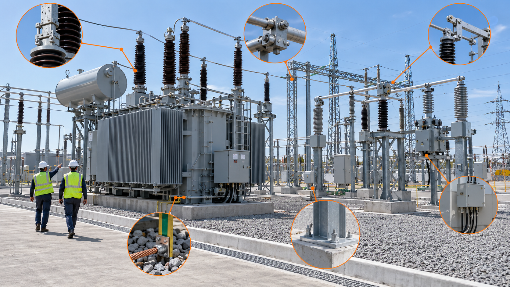
For an oil-immersed transformer, confirm oil level, valves, radiators, conservator, breathers, bushings, pressure devices, marshalling wiring, cooling controls and the absence of transport restraints. Review oil-processing and test records against the project procedure. For a dry-type transformer, inspect cleanliness, clearances, enclosure ventilation, winding supports, temperature sensors and cable terminations.
Electrical checks should confirm ratio, vector group, winding resistance trends, insulation condition, earthing, neutral arrangement, surge arresters, phase identification and CT circuits. Test methods and acceptance criteria depend on equipment design and the agreed project standard; unresolved deviations should be referred to the responsible engineer and manufacturer before energization.
Protection readiness extends beyond entering settings into a relay. Verify CT and VT ratios, polarity, wiring continuity, relay logic, circuit-breaker trip circuits, lockout relays and annunciation. Where practical and included in the commissioning plan, end-to-end testing should prove the complete path from simulated input to the intended breaker operation.
Interlocks should be checked under realistic states, including earthing-switch position, breaker truck position, isolator logic, door access and remote/local selection. Bypass links and test switches must be returned to the approved service position. Any temporary logic used for commissioning should be removed or explicitly controlled before the permit is issued.
Many energization failures originate in auxiliary systems rather than primary equipment. Verify the station service source, transfer logic, battery charger, DC distribution, trip-coil supply, alarm supply, emergency lighting and communications. Record battery condition and demonstrate that critical circuits remain available for the specified duty.
Check that transformer fans, pumps, heaters and tap-changer drives use the correct control voltage and phase sequence. Alarm and trip contacts should be traced to the correct local and remote indication. A system that can energize but cannot reliably trip, alarm or communicate is not ready.
Confirm permanent equipment earthing and bonding, including transformer tank, neutral equipment, switchgear, cable screens, structures and marshalling panels. Temporary earths must be listed and their removal or retention controlled by the switching program. Unrecorded temporary connections are a critical hazard.
Secure the energization boundary with fencing, locks, signs and controlled access. Remove construction tools, loose materials, scaffolding and temporary cables that could enter approach distances or obstruct emergency access. Fire detection, extinguishing equipment, oil containment and drainage should be available as required by the project design.
The switching program should use field equipment identifiers that exactly match drawings and labels. Define the switching authority, control-room interface, communication method, observer positions and stop-work authority. Include checks for source voltage, phase rotation, bus condition and expected indications at each step.

The contingency plan should identify what happens if a breaker fails to close, protection operates unexpectedly, voltage is abnormal, alarms appear or communications are lost. Restoration steps should not be improvised during the event. Contact details for the owner, EPC, commissioning team, utility and relevant equipment suppliers should be confirmed before switching begins.
The final meeting should record attendance, the energized boundary, approved documents, accepted exceptions and the validity period of the permit. If conditions change—such as settings, cabling, temporary earths, operating configuration or weather constraints—the permit should be reviewed again.
For supporting equipment and interface planning, review Zisheng Electric’s oil-immersed transformers, substation transformers and prefabricated substations. Related EPC checks are explained in our articles on the transformer site acceptance test checklist, transformer foundation interfaces, design change control and transport shock monitoring.
A controlled substation pre-energization readiness review converts dispersed construction and commissioning records into a defensible energization decision. Send Zisheng Electric the drawings, datasheets, load list, technical specification, single-line diagram, grid parameters, environmental conditions and installation-site constraints. We can coordinate transformer and substation equipment interfaces, documentation, factory records, site checks and technical clarifications with the EPC team. Our engineering team will review the requirements and respond to project inquiries within 24 hours.

A practical EPC transformer site acceptance test checklist covering delivery inspection, assembly, oil work, electrical tests, protection proving, energization and handover.
View details
Build an auditable transformer commissioning punch list with risk classes, accountable owners, closure evidence, temporary controls and an EPC energization release gate.
View details
Plan a controlled transformer oil filling procedure for EPC projects, covering vacuum, oil quality, circulation, sampling, leak checks and handover.
View details
In EPC projects, a transformer room must be designed as an operating space, not just a rectangle around the tank. Zisheng Electric engineers explain essential layout considerations including safety clearances, ventilation, lifting routes, and main...
View details