 zishengelectric





news
News Center
Providing high-quality power to the world
Search productSearch post
news
Providing high-quality power to the world
A transformer can leave the factory with a complete FAT report and still be unsafe to energize after delivery. Transport vibration, site storage, accessory reassembly, oil handling, cable work, protection wiring and unfinished civil interfaces all sit between FAT and first energization. A site acceptance test must close that gap.
For EPC enquiries, Zisheng Electric engineers normally ask for the commissioning method, approved drawings, protection cause-and-effect matrix, delivery records and site conditions before reviewing the test scope. A useful transformer site acceptance test checklist follows the equipment through arrival → assembly → electrical testing → protection proving → energization handover. It does not repeat the FAT report without checking what changed on site.
Factory acceptance testing verifies the manufactured unit against the approved specification under controlled workshop conditions. Routine electrical tests, functional checks, dimensional inspection and document review establish the dispatch baseline.
Site acceptance testing verifies that the delivered, assembled and connected transformer remains suitable for energization in the actual installation. In our commissioning review, we focus on what may have changed after dispatch: transport condition, oil-system integrity, installed accessories, earthing, cable or busduct interfaces, protection circuits and the readiness of adjacent equipment.
The SAT record also needs a clear link back to the final FAT baseline. Where site measurements are compared with factory values, tap position, terminal connection, temperature and test method need to be equivalent. A numerical difference is not automatically a defect, but an unexplained difference is not acceptable handover evidence.
| EPC Stage | Common Risk | What Must Be Confirmed |
|---|---|---|
| Arrival inspection | Impact, tilt, moisture entry or missing loose accessories | Transport recorder, packing list, seal condition, pressure or oil level and visible damage record |
| Mechanical assembly | Incorrect gasket, bushing torque, radiator valve position or unsupported pipework | Approved assembly procedure, torque record, valve checklist and leak inspection |
| Electrical connection | Wrong phase, inadequate clearance, loose joint or incomplete earthing | Phase identification, cable or busduct alignment, torque, earth continuity and as-built drawing |
| Protection and control | Alarm works locally but trip path or SCADA indication is incomplete | Point-to-point checks, cause-and-effect test, breaker trip proof and remote status |
| Pre-energization | Temporary earth, test link, open valve or wrong tap remains in service path | Independent walkdown, signed clearance certificate and final energization authorization |
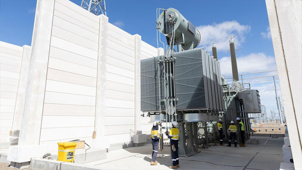
The first SAT evidence is created when the shipment arrives. During the arrival inspection, we check the main tank, conservator, radiators, bushings, control cabinet, cable boxes and separately packed accessories against the packing list. Package numbers, visible damage, displaced fittings, broken shock indicators, paint damage and any evidence that a crate has been opened are recorded before site assembly begins.
If impact or tilt recorders are specified, download and preserve the data before the device is removed. A threshold event does not automatically condemn the transformer, but it triggers an engineering review. The response may include internal inspection, additional electrical measurements or manufacturer guidance. The decision and its technical basis must enter the project record.
Check the transport preservation method. Depending on the unit, it may arrive oil-filled, partially oil-filled or under dry gas. Record tank pressure, oil level, seal condition and ambient temperature. If pressure is lost or moisture ingress is suspected, stop assembly until the agreed inspection and recovery procedure is approved.
Bushings, conservators, radiators, fans, oil pipes, relays and cable boxes may be removed for transport. Each component needs identification and a controlled installation sequence. Gasket surfaces must be clean, matched and compressed according to the approved method. Reusing a damaged gasket or applying uneven flange torque can create a slow leak that appears only after thermal cycling.
Valve positions deserve their own checklist. A closed radiator isolation valve can leave the transformer apparently normal at no load and cause serious overheating after loading. Incorrect Buchholz relay orientation or trapped air can produce false alarms and reduce protection effectiveness.
At Zisheng Electric, we normally ask the site team to return signed assembly and valve records with photographs of critical stages. This is more useful than a final statement saying “installation completed,” because the evidence shows what was actually checked.
Where site oil filling or treatment is required, hoses, tanks and processing equipment should be clean and suitable for transformer oil. Record oil batch identity, filtration and vacuum parameters, sample locations and test results. Avoid exposing active parts or dry insulation longer than the approved procedure allows.
The required oil tests depend on the unit, project specification and the work performed after delivery. Dielectric strength alone does not describe every aspect of oil condition. Moisture, dielectric dissipation factor, acidity, dissolved gases or other tests may be required depending on transformer size, transport state and commissioning plan. The approved project criteria, rather than a generic internet checklist, remain the acceptance basis.
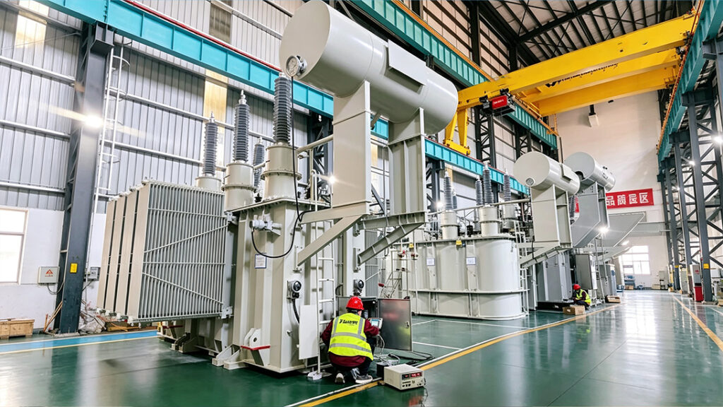
During the mechanical walkdown, we check foundation level, wheel orientation, anti-vibration pads, rail stops, anchoring, oil bund, drainage and fire separation. Radiator airflow and maintenance access are reviewed in the final installed condition, including the working space required for fans, pumps, bushings and tap-changer maintenance.
Cable and busduct loads must not be transferred into transformer bushings. Flexible connections, support spacing and thermal movement should match the approved interface drawing. Inspect minimum electrical clearances in the final installed condition, including temporary scaffolding, handrails and cable cleats that were not present on the transformer GA.
Earthing is more than one tank earth lead. Verify the main tank, marshalling kiosk, cooler frames, cable boxes, neutral equipment, surge arresters and any isolated metalwork. Measure continuity using the project procedure and confirm that the earthing arrangement matches the approved single-line diagram and protection study.
The SAT test list depends on transformer design, voltage class, transport condition and utility requirements. Common checks may include insulation resistance, polarization behavior where applicable, winding resistance, ratio and vector group, capacitance and dissipation factor, bushing tests, oil tests and functional checks. Large or critical units may require additional diagnostic measurements under the project specification.
Do not repeat a test merely because it appears on another project’s form. Ask what changed after FAT and what risk the site measurement controls. Winding resistance can reveal a loose installed link or connection. Ratio and vector checks can confirm tap and phase identification. Bushing capacitance comparison may identify transport or assembly damage. Insulation-resistance trends can support dryness assessment, but temperature and test conditions must be recorded.
Site results should be compared with factory baseline values after appropriate correction. If the methods differ, the engineer must state the limitation. A pass/fail label without raw values, conditions and instrument details is weak evidence.
| SAT Input | Why It Matters | Procurement or Commissioning Check |
|---|---|---|
| Final FAT report | Provides the dispatch baseline and guaranteed values | Confirm serial number, tap, temperature, instrument and approved revision |
| Transport and storage log | Explains exposure, impact and preservation history | Review recorder events, pressure or oil level and storage inspections |
| Site test procedure | Defines methods, safety controls and acceptance criteria | Obtain approval before testing and identify witness or hold points |
| Protection cause-and-effect matrix | Connects transformer devices to breaker trips, alarms and SCADA | Prove the entire path, not only the local contact |
| As-built single-line and wiring drawings | Establish final phase, neutral, CT and trip connections | Close red lines before energization authorization |
| Punch-list register | Separates cosmetic work from energization-critical defects | Assign owner, due date and formal concession for any accepted open item |
Transformer accessories often pass an individual continuity test while the complete protection path remains unproven. Simulate or operate each device according to the approved procedure: oil and winding temperature alarms, pressure relief indication, gas relay stages, oil level, cooler failure and tap-changer alarms where applicable.
Trace the signal through terminal blocks, interposing relays, protection panels, trip coils and SCADA. Confirm the correct breaker trips, the correct alarm appears and event time stamping is coherent. Verify fail-safe behavior for loss of DC supply or broken supervision circuits if required by the design.
The published guide on closing transformer technical interfaces in EPC projects explains why datasheets, GA drawings, protection settings and document registers must close together. The EPC transformer supply process from design to delivery provides the upstream context for the SAT handover package.
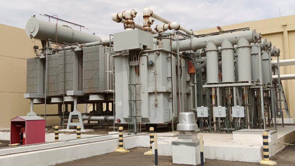
The final walkdown should be independent from the team that performed the last connection work. Confirm the selected tap, neutral connection, phase sequence, bushing and cable-box closure, oil level, valve positions, cooler power, heater supply, protection DC, breaker status, surge arrester earths and all temporary test links.
Remove temporary earths under the project safety system and record the removal. Check that tools, rags, blanking plates and transport braces are not left in or near the equipment. Verify labels against the single-line diagram and switching schedule. Confirm that fire systems, drainage, fencing, lighting and access control are ready.
Open punch items must be classified. Paint touch-up may be completed after energization if the owner accepts it. An uncertain valve position, incomplete trip circuit or missing earth connection cannot be treated the same way. The commissioning manager should sign the energization certificate only after critical items are closed or covered by an approved technical concession.
Agree the switching sequence, responsible persons, communication channel and abort criteria before energization. Keep the secondary side unloaded unless the approved procedure states otherwise. Observe inrush-related protection behavior, sound, vibration, oil level, pressure, leakage and local indications. Confirm phase voltage and rotation at the appropriate points before connecting load.
After the stabilization period defined by the project, recheck the transformer and connected equipment. Inspect for oil seepage, abnormal temperature, fan or pump operation and unexpected alarms. Loading should follow the approved sequence, particularly where motors, converters or large cable charging currents are present.
Use an appropriate high-voltage power transformer, medium-voltage switchgear and prefabricated substation interface package only after the switching, protection and mechanical boundaries are agreed. Equipment compatibility is established through coordinated drawings and tests, not by placing compliant products beside each other.
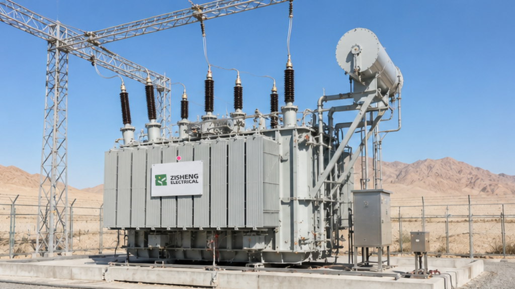
A complete handover file should include the approved SAT procedure, calibrated instrument records, raw and corrected test values, oil reports, assembly and torque records, valve checklist, protection functional-test sheets, as-built drawings, red-line closure, punch-list status, energization record and baseline photographs.
For a project-specific transformer site acceptance test checklist, send the transformer datasheet, single-line diagram, approved GA, FAT report, transport method, site assembly scope, protection matrix, cable schedule, earthing design and commissioning specification.
Zisheng Electric can provide technical matching based on project capacity, voltage level, environmental conditions and technical specifications. Our engineering team will review the requirements and respond to project inquiries within 24 hours.

Plan a controlled transformer oil filling procedure for EPC projects, covering vacuum, oil quality, circulation, sampling, leak checks and handover.
View details
Plan a substation pre-energization readiness review covering punch lists, transformer checks, protection tests, station DC, switching and permit controls.
View details
Build an auditable transformer commissioning punch list with risk classes, accountable owners, closure evidence, temporary controls and an EPC energization release gate.
View details
In EPC projects, a transformer room must be designed as an operating space, not just a rectangle around the tank. Zisheng Electric engineers explain essential layout considerations including safety clearances, ventilation, lifting routes, and main...
View details