 zishengelectric



news
News Center
Providing high-quality power to the world
Search productSearch post
news
Providing high-quality power to the world
Substation revenue metering handover should demonstrate that an accepted measurement chain produces correctly identified energy records at the agreed commercial boundary. A meter that lights up, communicates and displays a plausible number has not yet established that result. The instrument transformers, wiring, configuration, register mapping and receiving system must agree with the approved metering design.
For an EPC project, separate equipment completion from utility or owner acceptance. Define who supplies each part, who witnesses the checks and who can authorize the metering arrangement for its intended use. This guide proposes an evidence workflow; the applicable utility requirements, contract, selected equipment manuals and approved commissioning procedure determine the actual acceptance criteria.

Start with an approved single-line diagram identifying the contractual measurement point. State which feeder, incomer or transformer circuit is measured and whether the installation includes a main meter, a check meter or internal monitoring only. Record the utility service reference and project equipment tags where applicable. A label such as “incoming meter” is insufficient when several incoming circuits exist.
Identify the parties responsible for the meter, current transformers, voltage transformers, secondary wiring, test facilities, communication equipment and remote data service. The party supplying a cabinet may not be the party authorized to configure or seal the revenue meter. Make the interfaces explicit before factory testing so that an excluded utility activity is not mistaken for completed EPC work.
Confirm whether the approved scheme applies compensation or other transformations between the physical measurement point and the commercial reporting point. If it does, retain the authority, calculation basis and configuration record. Never add a generic transformer-loss adjustment simply because a meter is installed on one side of a transformer. This must follow the project’s accepted commercial and engineering arrangement.
The handover plan should answer three questions: Is the installed measurement chain the approved one? Does the system record the agreed quantities with the required identity and scaling? Has the authorized party accepted the result? These questions require different records. A calibration certificate supports a defined instrument claim; it does not by itself establish correct site wiring or utility approval.
Build a schedule linking each meter serial number and firmware version to its equipment tag, location and purpose. Link each associated CT and VT to the selected winding or core, ratio, accuracy designation and approved burden information. Record the installed tap or connection where selectable arrangements exist. Keep the original equipment certificates connected to the installed identity rather than collecting them in an unindexed folder.
Review the secondary circuit from instrument transformer to meter against the approved drawings. The inspection record should identify the relevant terminals, phase allocation, polarity references, cable identification and test facilities. Distinguish a visual wiring inspection from an electrical verification. The commissioned arrangement must match the final drawing, including accepted field changes.
Coordinate changes through the substation as-built drawing reconciliation process. A corrected meter configuration cannot close a drawing discrepancy that still directs the next technician to the wrong terminals. Conversely, a marked-up drawing does not demonstrate that the wiring has actually been corrected and retested.
All inspection and testing must be planned and performed by qualified personnel under the approved safety arrangements. CT secondary circuits require specific controls; do not disconnect them casually or use this article as a switching procedure. The test authority must define isolation, test connections, restoration and permission boundaries before work starts.

Reconcile the meter configuration with the installed CT and VT data. Record the relevant primary and secondary settings, system arrangement, frequency and phase association supported by the selected device. The check should use the accepted configuration record and installed equipment evidence, rather than copying settings from a nearby panel that appears similar.
Schneider Electric’s meter troubleshooting guidance identifies configuration values, CT/VT polarity and application-specific wiring as relevant checks when readings are incorrect. This supports checking the measurement chain as a whole. It does not provide project-specific revenue acceptance limits or substitute for the selected meter’s manual.
For every quantity sent to a remote system, state whether the source value already includes the instrument-transformer ratio. Record the unit, scale factor, data type, register address or object identifier, and destination tag. A collector that applies the ratio again can produce a consistent-looking but incorrect result. A local display comparison alone will not reveal that error unless the remote value is included.
Define import and export directions in words and reference them to the approved single-line diagram. Identify which registers accumulate each direction and how the receiving system labels them. Where reactive quantities, demand values or time-based tariff registers are required, document their agreed meaning and interval basis. Do not infer settlement conventions from a generic meter display or a familiar abbreviation.
Retain an approved configuration export where the device supports one, together with a human-readable settings record. Record who applied it, which revision was used and what changed during commissioning. A filename containing “final” is not version control. The accepted device identity and configuration revision should appear on the test report and the handover index.
Agree the evidence matrix before the witness visit. Each check needs an owner, acceptance reference, result and treatment for unresolved findings. The following structure can be adapted to the utility and contract requirements; it does not introduce universal test tolerances.
| Check | Required evidence | Closure question |
|---|---|---|
| Measurement boundary | Approved diagram and responsibility schedule | Does every party agree what is being measured? |
| Equipment identity | Serial-number schedule, certificates and installed core/tap records | Do the records describe the installed equipment? |
| Wiring and phase association | Approved procedure, inspection and test results | Has the actual circuit been verified within the recorded test boundary? |
| Ratios and scaling | Meter settings and collector mapping | Are ratios and units applied correctly across the chain? |
| Energy direction and registers | Defined conventions and witnessed functional evidence | Do local and remote records represent the intended quantity? |
| Time and intervals | Clock configuration and timestamped sample exports | Can the recipient place each interval correctly? |
| Remote collection | Delivery test and approved interruption-recovery case | Are missing, repeated or invalid records recognized? |
| Acceptance and custody | Authorized sign-off, sealing record where required, and access handover | Is the system accepted for its stated purpose? |
Record what each test actually demonstrates. A secondary injection test and a primary-system check have different boundaries. A simulated register value can demonstrate mapping without proving the full measurement circuit. Identify these distinctions on the report and carry any remaining scope into the site acceptance plan.
When a result is outside the approved criteria, preserve the original evidence and open a traceable finding. Record the cause assessment, authorized correction and retest scope. Do not overwrite the first result with a successful repeat and lose the reason for the change. The accepting party should be able to follow the decision without reconstructing an email chain.
Witness the required path from the meter to the receiving system using identifiable test data and an agreed observation window. Compare equipment identity, quantity, unit, direction and timestamp at both ends. Confirm whether the receiver shows raw or transformed values. Preserve a small, clearly labeled sample dataset that the operator can use as a reference.
Coordinate the clock source, time zone, interval boundaries and treatment of time changes with the substation time synchronization acceptance plan. Recording a correct instantaneous value does not establish that an energy interval has been placed in the correct reporting period. Document the project’s chosen convention rather than assuming all devices display the same time basis.
Where the contract requires resilience to communication interruption, agree a controlled recovery test. Identify the expected buffering, retrieval and gap-detection behavior supported by the supplied system. Verify the recovery evidence against those requirements. Do not promise lossless recovery simply because a meter has local memory; retention, collection settings and interruption duration all matter.
Use the point-to-point testing workflow for relevant monitoring interfaces while keeping commercial metering acceptance identifiable. A value visible on SCADA may support operations but still be outside the utility’s approved data-delivery path. State which destination was demonstrated and which authority accepts it.

Prepare a concise dossier containing the approved metering diagram, equipment schedule, certificates, final wiring drawings, accepted configuration, mapping list, test reports, sample data and open-item register. Include the utility or owner acceptance record required by the project. If an approval is pending, identify it as pending rather than describing the whole installation as revenue-ready.
Hand over access and responsibilities through the authorized process. Identify who can retrieve records, modify settings, investigate missing data and request a metering intervention. Keep credentials out of publicly circulated test reports. Where sealing or controlled access applies, record the accepted custody arrangement and the procedure for authorized future changes.
Demonstrate routine retrieval to the receiving operator using the delivered tools and documentation. Ask the operator to locate a meter by tag, identify the accepted configuration, retrieve a sample period and recognize an unresolved data gap. Record the demonstration and any training actions. A completed folder transfer is weaker evidence than a usable retrieval process.
No. It supports the scope stated on the certificate. Installed wiring, ratios, register meaning, remote data delivery and the applicable utility acceptance remain separate parts of the project’s handover.
Use only the arrangement accepted by the responsible designer and utility for the specified duty. Do not substitute cores based solely on ratio or available terminals; the complete metering requirement must be checked.
The remote system may apply scaling, naming or time transformations. Comparing the complete path helps establish that the delivered records retain the intended quantity, equipment identity and reporting period.
The contract determines the permitted release stages. Record the exact completed scope and outstanding approval. Do not treat a conditional equipment handover as authorization for commercial settlement.
Changes to meters, CT/VT connections, ratios, firmware, configuration, register mapping or the receiving system should enter the project’s change process. The responsible authority determines which checks and approvals must be repeated.
For a transformer or packaged-substation enquiry, provide Zisheng Electric with the approved single-line diagram, metering boundary, utility requirements, equipment ownership schedule and required witness records. Review the prefabricated substation and medium-voltage switchgear package interfaces against those documents. Product descriptions do not establish inclusion of a utility-approved meter or a particular data service; confirm the offered scope and exclusions in the project schedule.
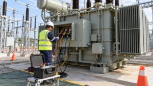
Use a repeatable transformer winding resistance site test procedure for EPC handover. Record tap position, temperature, test current, stabilization and OEM comparison basis without inventing universal acceptance limits.
View details
Plan substation emergency lighting handover with approved area boundaries, circuit schedules, source-failure tests, battery duration evidence, punch closure and operator maintenance records.
View details
Plan a substation water ingress walkdown for EPC handover: inspect roof drainage, thresholds, cable penetrations, trenches and electrical enclosures; assign repairs and release evidence.
View details
Plan a transformer first-service thermal survey with safe access, representative load records, cooling checks, evidence ownership and clear EPC handover decisions.
View details