 zishengelectric





news
News Center
Providing high-quality power to the world
Search productSearch post
news
Providing high-quality power to the world
A transformer can be electrically correct and still create an EPC delay when the cable termination does not fit the bushing arrangement. The problem usually appears late: the transformer is already in production, the civil foundation is cast, the cable contractor has ordered terminations, and the switchgear supplier is working to a different phase spacing. At that point, a small drawing mismatch becomes a site modification, a rework instruction, or a commissioning hold.
At Zisheng Electric, we treat the transformer cable termination interface as a controlled design package. The chain is source → transformer bushings or cable box → MV/HV cables → switchgear → protection and control. Each interface has mechanical, electrical, thermal, earthing, testing, and access implications. This guide sets out what EPC contractors should freeze, what the manufacturer should return, and what must be checked before the transformer is released for fabrication.
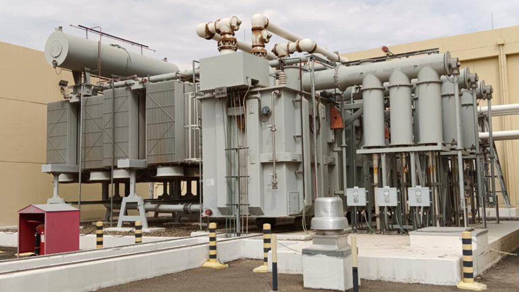
Transformer datasheets often state voltage, current, insulation level, and terminal type, but they do not always capture the installation geometry that the cable contractor needs. A cable termination requires bending radius, straight length, phase spacing, screen bonding, stress-control clearance, gland position, and a safe working envelope. A bushing may be top-entry, side-entry, or mounted inside a cable box. A switchgear lineup may require the cables to approach from below, from a trench, or through a rear compartment. If those assumptions are not on one controlled drawing, each supplier fills the gap differently.
| EPC Interface | Common Risk | What Should Be Confirmed Before Production |
|---|---|---|
| Transformer bushing or cable box | Terminal type or phase spacing does not suit the selected termination | Bushing drawing, conductor size, screen arrangement, phase centres, clearances, entry direction |
| Cable route and trench | Bending radius or pulling space is unavailable | Finished civil levels, trench width/depth, cable length, pulling direction, removable covers |
| Switchgear cable compartment | Transformer outlet does not line up with the panel termination zone | Panel GA, cable entry height, phase order, gland plate, segregation, earthing bar |
| Protection CTs and sensors | CT location or polarity conflicts with relay scheme | CT ratio/class, physical location, terminal schedule, polarity marks, test links |
| Earthing and cable screens | Uncontrolled circulating current or unsafe touch voltage | Single-line diagram, earthing study, screen-bonding method, accessible earth points |
| Testing and commissioning | Insulation or sheath tests cannot be performed safely | Isolation points, test bushings, test links, temporary earth points, approved procedure |
The cable termination cannot be selected from voltage alone. Before we freeze the termination arrangement, we normally ask for the system nominal voltage, highest voltage for equipment, frequency, short-circuit level, insulation coordination, neutral and earthing arrangement, cable conductor material and cross-section, number of parallel runs, screen type and the selected termination family. The final selection may be a separable connector, heat-shrink, cold-shrink, or another approved system. The transformer supplier must know the actual termination make and model when the mechanical interface is frozen.
For a 110 kV or 115 kV unit, the interface may use condenser bushings and outdoor cable sealing ends rather than the arrangement used on a medium-voltage distribution transformer. Zisheng Electric’s 110kV/115kV power transformer range illustrates why the bushing schedule and installation method belong in the equipment package, not in a late site note.
Higher voltage classes impose stricter clearances, field-control requirements, test arrangements, and handling procedures. A cable termination may need a defined stress cone position, a minimum distance to steelwork, and a clean, dry installation environment. If the transformer tank, cable box, or support steel enters that field-control zone, the design can fail during commissioning even though the nameplate voltage is correct.
At medium voltage, the same principle applies at a different scale. We normally review the switchgear cable-compartment dimensions, phase centres, gland plate, earthing bar and access doors against the transformer outlet drawing as one interface.
A useful interface drawing puts the transformer outline, bushing centre lines, cable box, removable covers, cable entry, termination envelope, trench or support steel and receiving switchgear on the same dimensional reference, with clear datums and finished levels. A drawing that shows only the transformer side cannot prove that the cable will physically reach the switchgear.
Include a responsibility matrix. The transformer manufacturer owns the bushing and cable-box dimensions. The cable supplier owns the termination installation envelope and bending requirements. The switchgear supplier owns the panel cable-compartment geometry. The civil contractor owns the trench and foundation levels. The EPC contractor owns the consolidated interface drawing and revision control. “By others” is not a technical resolution.
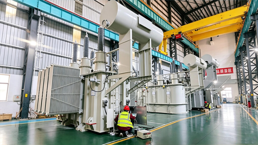
During our mechanical interface review, we check the cable entry side and height, gland-plate thickness and hole pattern, support brackets, and the distance from the termination stress cone to grounded metal. Cable bending radius is checked against the cable manufacturer’s minimum-temperature requirement rather than only against room-temperature installation conditions. We also confirm whether the cable must be pulled before the transformer is set on its final foundation. Where a removable roof or side panel is required for installation, its removal envelope needs to be shown on the GA drawing.
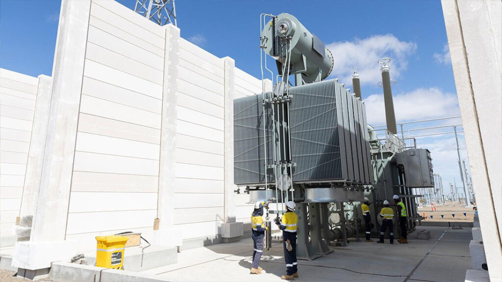
Foundation and access details are equally important. Wheels, jacking pads, lifting lugs, radiator projections, marshalling boxes, and cable boxes can conflict with anchor bolts or trench covers. A compact transformer package may save floor area and still be impossible to terminate if the cable contractor cannot stand in the required working position.
For packaged systems, the prefabricated compact substation layout should be reviewed as one assembly: transformer compartment, MV switchgear, LV board, cable corridors, ventilation, fire separation, and access doors. Treating each compartment as a separate vendor package creates avoidable offsets.
Outdoor cable boxes need drainage, sealing, UV-resistant materials, corrosion protection, and a maintenance approach for rain or dust. Indoor rooms may have tighter clearances, restricted lifting paths, and ventilation or fire requirements. For coastal or desert projects, we need humidity, salt exposure, dust, ambient temperature and altitude defined in the same interface schedule before enclosure and coating requirements are finalized. The appropriate enclosure and coating cannot be selected from a project nickname such as “Gulf model.”
Phase order must be consistent from the transformer drawing to the cable schedule, switchgear labels, and protection settings. Do not rotate phases in the field to compensate for an unclear drawing. Confirm neutral location, transformer tank earth, cable-screen bonding, cable-box earth bar, and any removable test link. For single-core cables, the bonding method can influence circulating current and induced sheath voltage; the earthing study and cable supplier’s installation instructions should control the final arrangement.
CTs, surge arresters, capacitive voltage indicators, and temperature or pressure contacts may sit near the cable interface. Their physical and electrical data should appear in the terminal schedule. Protection wiring is not a substitute for a cable-termination drawing, but both documents must use the same equipment tags and phase references.
Before witnessing the electrical tests, we include a document walk-down in the factory acceptance review. The as-built GA, bushing schedule, cable-box drawing, nameplate, terminal schedule, accessory list and interface responsibility matrix are checked against the approved revision, together with the supplied cable-box hardware, earth bars, gland plates and removable covers.
Routine transformer tests do not prove that a site cable will fit. For this reason, we treat the cable interface as a separate pre-dispatch inspection point rather than assuming routine transformer tests have covered it. Phase centres, entry dimensions, support locations, access openings and clearances can then be measured against the approved drawing before shipment. Photograph the measured points with a scale and reference the drawing revision. If a termination kit is available at the factory, a dry-fit check can reveal interference without applying electrical stress.
The EPC technical interface closure guide and the transformer supply process from design through FAT and delivery show how interface evidence should remain connected to the project document package.
| Pre-Dispatch Hold Point | Evidence Required | Release Decision |
|---|---|---|
| Approved interface drawing | Latest revision signed by transformer, cable, switchgear, civil and EPC parties | No conflicting dimensional assumptions remain |
| Termination compatibility | Selected kit data sheet, cable dimensions, phase spacing and clearance check | Kit can be installed within the shown envelope |
| Earthing and screens | Earthing drawing, screen-bonding method, labelled earth points | Commissioning team has a defined connection method |
| Factory dimensional inspection | Measured GA points, photos, punch-list closeout | As-built equipment matches the approved drawing |
| Shipment protection | Removal list, blanking plates, covers, packing and reassembly instructions | Interface parts are protected and traceable during transport |
Large bushings, cable boxes, radiators, and support brackets may be removed for transport. The packing list must identify each removed component, its tag, fasteners, seals, lifting method, and reassembly torque or procedure where applicable. The site team should receive an installation drawing that distinguishes factory-installed items from field-installed items.
At unloading, inspect flange faces, porcelain or composite surfaces, cable-box covers, gland plates, earth bars, and accessory wiring before moving the transformer into position. Verify foundation levels and cable-trench dimensions again. A transport impact indicator or visual inspection cannot replace the specified electrical checks, but it can identify handling events that require engineering review.
Interface control is also a change-control problem. A cable supplier may change conductor diameter, a switchgear supplier may revise the panel layout, or a civil contractor may move the trench wall. Any change to cable dimensions, switchgear geometry or trench position needs to be checked against the transformer GA, termination envelope, earthing drawing, protection schedule and packing arrangement before the revision is released. The EPC document controller should issue one transmittal and record the affected revision, responsible reviewer, decision, and date. Uncontrolled redlines left at site are not a reliable as-built record.
Before energization, confirm transformer position, phase labels, cable support, termination stress-control installation, screen bonding, earth continuity, torque records, clearances, phase sequence, and protection test links. Perform the cable and transformer tests required by the approved commissioning procedure. Record any temporary earths or test links removed before energization.
Do not close the final punch list on the basis of “cable connected.” The commissioning record should identify the cable circuit, termination kit, transformer terminal, phase, test result, and responsible contractor. This traceability is valuable when a later trip appears to be a transformer problem but is actually a termination or screen-bonding defect.
For a transformer cable termination interface review, send the single-line diagram, transformer datasheet, cable schedule, termination data sheet, switchgear GA, civil foundation and trench drawings, earthing study, protection terminal schedule, project specification, and site conditions. Zisheng Electric can coordinate oil-immersed power transformers, dry-type transformers, compact substations, MV switchgear, and related distribution equipment around a controlled EPC interface.
Zisheng Electric can provide technical matching based on project capacity, voltage level, environmental conditions, and technical specifications. Our engineering team will review the requirements and respond to project inquiries within 24 hours.
Coordinate transformer condition monitoring for EPC projects: sensors, SCADA points, alarm ownership, communications, FAT, commissioning and data handover.
View details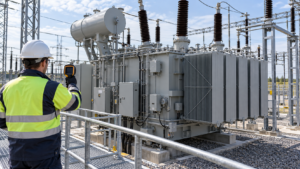
Plan a transformer first-service thermal survey with safe access, representative load records, cooling checks, evidence ownership and clear EPC handover decisions.
View details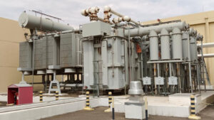
Full-cycle EPC transformer service covering design freeze, manufacturing, FAT, overseas logistics, on-site installation and commissioning for Middle East and Africa power projects.
View details
In EPC projects, a transformer room must be designed as an operating space, not just a rectangle around the tank. Zisheng Electric engineers explain essential layout considerations including safety clearances, ventilation, lifting routes, and main...
View details