zishengelectric



news
News Center
Providing high-quality power to the world
Search productSearch post
news
Providing high-quality power to the world
Zisheng Electric treats the substation fence earthing interface as a coordination issue that must be resolved before a fencing package is released for construction. A perimeter drawing can look complete while leaving unanswered questions about gate leaves, security equipment, neighbouring metalwork and the relationship between the fence and the station earthing design. Those gaps become expensive when the fence is installed before the electrical designer has reviewed its final position.
This guide helps EPC engineers, owners and package buyers define responsibilities and evidence. It is not an earthing design calculation or a universal instruction to connect every fence to the station grid. The responsible earthing engineer must determine the arrangement using the project study, local requirements and the asset owner’s approved standards. The practical objective is to keep that decision visible through procurement, construction and handover.
Request one coordinated drawing that distinguishes the station perimeter, internal equipment barriers, public access areas, gates and adjacent property boundaries. Mark the proposed earthing arrangement and the limits of each contract. A line labelled “fence by others” is a commercial allocation; it does not establish who owns the electrical interface or approves a change.
The drawing should identify nearby conductive items that require review, including handrails, pipelines, cable supports, drainage structures and security installations. Their significance depends on the design. Do not infer a safe arrangement from apparent distance on a small-scale general arrangement. Bring the earthing designer into the review before the civil team freezes fence posts and gate foundations.
Record the exact study and drawing revisions used. Soil information, fault assumptions, clearing times, site geometry and accessible locations belong to the designer’s assessment. The procurement team need not reproduce that analysis, but it must know which approved document controls the fence package and which changes require the analysis to be revisited.
Fencing cannot be reduced to a standard list of copper straps and clamps. Depending on the approved scheme, particular sections may require bonding, separation or other design provisions. A generic instruction to “earth all metalwork” can undermine an intentionally separated arrangement. Equally, omitting a specified connection because a fence appears remote from primary equipment can invalidate the intended protection.
Utility documents illustrate why project-specific review matters. Ausgrid’s NS222 major-substation earthing standard addresses fence continuity, gate bonding and the possibility that security installations bridge intended isolation. These are requirements within that utility’s context, not a universal drawing for every EPC site. Use the applicable owner’s current requirements and the approved project study to select details.
The tender should therefore request a coordinated connection schedule rather than an unsupported resistance target. Each scheduled item should reference a location, approved detail, material interface and verification requirement. Leave engineering choices open only when the contract clearly assigns the design responsibility and defines how the final solution will be approved before installation.
The matrix below is a recommended coordination framework. It does not prescribe conductor sizes, spacing, test limits or a particular connection philosophy. Replace the example responsibilities with the parties and approval authorities actually appointed to the project.
| Interface | Decision to obtain | Evidence before release | Typical coordinating party |
|---|---|---|---|
| Perimeter position | Does the final fence route match the earthing assessment? | Coordinated civil and electrical layout with revision references | EPC design lead |
| Fixed fence sections | Which sections require continuity or intentional separation? | Approved connection and isolation details | Earthing designer |
| Gate leaves and movement | How is the required electrical arrangement maintained through travel? | Gate detail, movement review and inspection requirements | Fence supplier and electrical contractor |
| Security devices | Could power, data or mounting hardware bridge a design boundary? | Reviewed device layout and cable routes | Security integrator |
| Buried interfaces | What must be inspected before backfill or concrete placement? | Inspection hold points and location records | Civil and electrical supervisors |
| Handover | Who accepts the installed arrangement and remaining changes? | As-built drawings, specified test records and closed discrepancies | Owner’s authorised representative |
One named coordinator should track these interfaces through the design register. Shared responsibility is useful for technical input, but an action assigned simply to “civil/electrical/vendor” often remains unresolved. Give each open decision an owner, required input and date linked to the construction sequence.
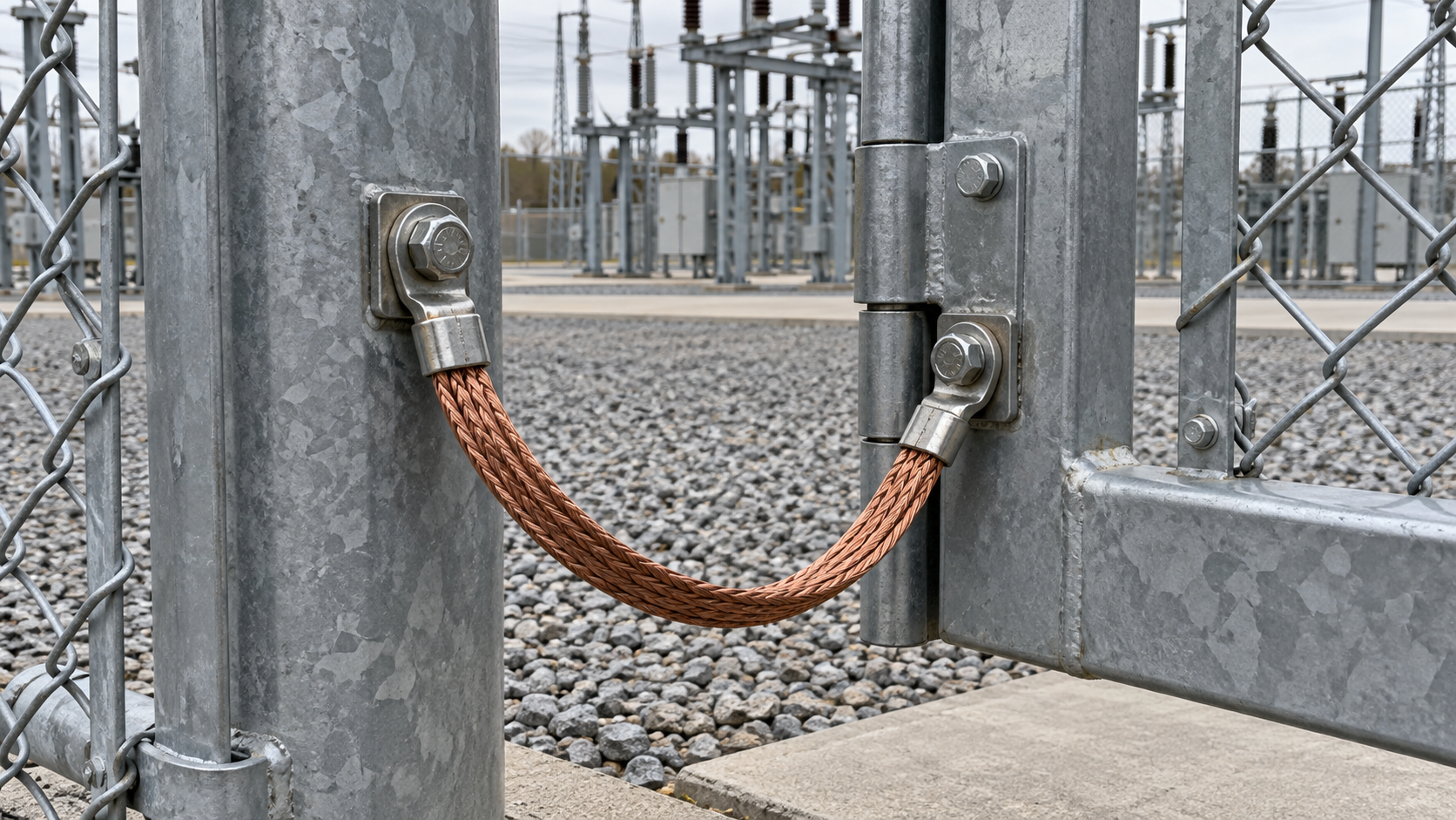
A gate is a moving assembly, so a detail that works on a fixed post may not remain suitable through opening and closing. Where the approved design requires a flexible connection, review its routing throughout the intended movement. It should not be stretched, trapped, abraded or forced into a hinge mechanism. Check the actual installed travel, including the position used for large equipment delivery.
Do not treat hinges as demonstrated electrical continuity merely because the gate opens smoothly. The approved design and verification method establish whether the arrangement is acceptable. A photograph of a braid is also incomplete evidence: it may show presence without proving attachment quality, compatibility or the required electrical result.
Ask how the connection can be inspected and renewed under the owner’s safe working arrangements. A detail hidden behind a gate motor or inaccessible after paving may create a recurring maintenance problem. Identify replaceable items, access requirements and the instructions the owner needs when the gate drive, hinges or leaf are changed.
Gate automation introduces additional interfaces. The motor enclosure, power cable, controls and access-control devices should appear in the coordinated package. An accessory added late by a security subcontractor is still part of the electrical design review if its installation affects a defined boundary. Commercially small additions should not bypass that review.
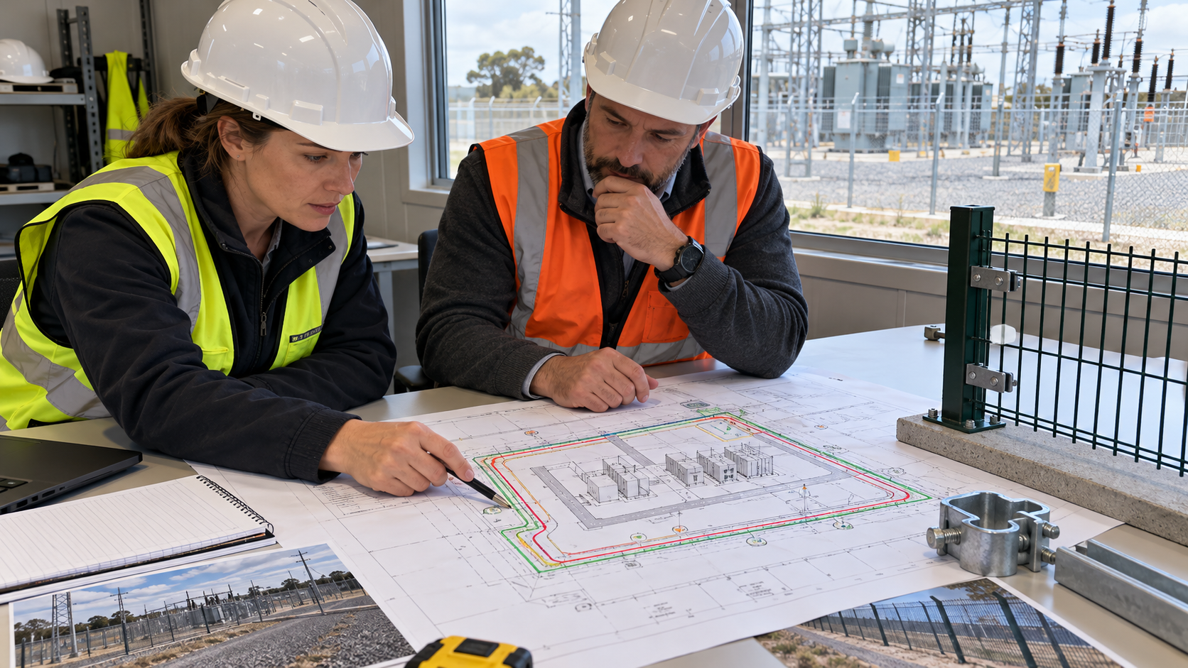
Cameras, intrusion sensors, access readers and lighting supports are often procured separately from the fence. Their brackets and cable routes can create connections that are absent from the original electrical drawing. Require the security integrator to submit physical mounting and cable-routing information, not only an equipment list and a functional diagram.
Review conductive services and their proposed interfaces without assuming that all data links have the same electrical characteristics. The designer should know what is actually supplied and how it crosses the boundary. A product described commercially as a network device does not remove the need to assess its power supply, metallic cable components or mounting arrangement.
Civil works can change the arrangement just as easily. A revised drain, retaining wall, vehicle barrier or paved approach may affect the location or accessibility of installed components. Coordinate these changes with the earthing designer before construction. Link the interface register to the project’s lightning mast interface review when supporting structures or nearby installations share design decisions.
For a brownfield boundary, distinguish verified existing information from assumptions. Old drawings may not show later gates, repairs or services. Assign the survey and any necessary investigation to qualified personnel working under the site’s access and safety procedures. The bid package should clearly identify unresolved information instead of presenting an incomplete drawing as an established condition.
Agree inspection points around the construction programme. Some interfaces become difficult to verify after backfill, concrete placement, painting or equipment installation. The inspection and test plan should identify which details require review before concealment, who receives notice and what records allow work to proceed. A late request for photographs cannot recover an unrecorded buried detail.
Location records should allow a future reviewer to find the inspected item. Use consistent identifiers on the drawing, inspection sheet and image record. Include the relevant approved revision and note any deviation. A close-up without a location reference can be useful for workmanship discussion but weak as evidence that every required connection was installed.
The approved test procedure must define the method, instrument suitability, safety controls and acceptance basis. Avoid importing a single resistance value from another project. A measurement is meaningful only in relation to the required test boundary and the design criteria. The appointed engineer should decide which inspections and measurements establish the required condition.
Keep these records connected to the transformer installation quality dossier where the perimeter interfaces affect the equipment handover boundary. This cross-reference lets the owner trace an installation decision without mixing unrelated test results into one generic acceptance sheet.
A wider gate, relocated post or new security cabinet may appear to be a small site adjustment. Require a change request that identifies the original arrangement, proposed arrangement and affected documents. The earthing designer should assess whether the study or connection details need revision before the change is released.
Separate temporary construction fencing from the final perimeter. Temporary barriers and delivery openings need their own approved arrangements for the relevant construction stage. Do not assume that a final-design acceptance automatically covers temporary positions or incomplete sections. The site safety team and responsible engineers must establish the applicable controls.
Procurement should also control material substitutions. A substitute clamp, conductor assembly or coated component should be reviewed for its intended application, mechanical compatibility and environmental exposure. Visual similarity and a supplier statement that an item is “equivalent” are insufficient when the approved connection detail specifies particular performance or installation conditions.
Keep rejected proposals in the change history. When a later contractor sees an earlier drawing, the record should explain why it was superseded. That small administrative step helps prevent a previously rejected detail from returning during replacement work or an expansion.
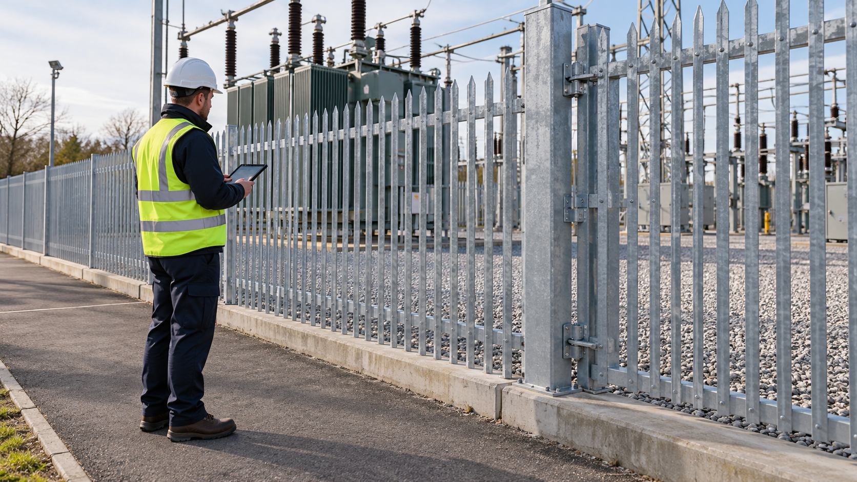
The final review should follow the installed boundary, including gates, corners, service crossings and security additions. Compare the field arrangement with the approved as-built package. Check that required inspection and test records refer to the installed configuration, and that changes made after testing have been assessed for any repeat verification.
A closed construction action is not automatically an accepted engineering deviation. The owner should receive the disposition, supporting evidence and approval authority for each remaining exception. Route unresolved items through the commissioning punch-list process, with consequences and release authority stated explicitly.
Hand over maintenance information alongside the drawings. Identify inspection access, replaceable gate connections, recorded alterations and the process for reviewing future security additions. The perimeter will change during the life of a substation; a useful handover package helps the owner recognise when a routine alteration needs engineering review.
Zisheng Electric can review the equipment-side information needed for the substation fence earthing interface alongside enquiries for 10kV-class oil-immersed distribution transformers and 20kV-class oil-immersed distribution transformers. The project earthing designer remains responsible for the approved site arrangement. Provide drawings, data sheets, load lists, technical specifications, single-line diagrams, grid parameters, environmental conditions and installation-site conditions, together with the perimeter layout, earthing-study references and security-device schedule. Our engineering team will review the requirements and respond to project inquiries within 24 hours.

Plan substation DC earth fault location acceptance with verified feeder identities, monitoring boundaries, alarm interfaces and traceable handover evidence.
View details
Plan substation DC battery commissioning for EPC handover: verify duty, charger alarms, remote load voltage, discharge evidence and ownership boundaries before acceptance.
View details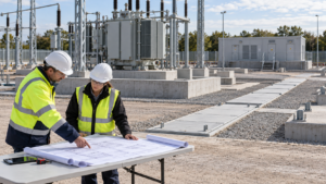
Coordinate substation underground services before excavation: resolve cable, drainage and earth grid clashes, assign decisions and capture buried-work records.
View details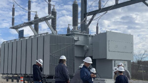
After years of working on-site with EPC projects, I have realized one critical truth: although transformers seem to be standard electrical equipment, every actual project requires customized support. Tiny differences in design parameters, dimensio...
View details